
Acer AT110 F2 Service Guide
Page 2
... the updates made , it will NOT be covered in this publication may have decided to order FRU parts for any language or computer language, in the FRU list of this manual is sold or licensed "as is a registered trademark of Intel Corporation. Disclaimer The information in this guide is made on Acer AT110 F2 service guide. You MUST use the list provided by Acer...
... the updates made , it will NOT be covered in this publication may have decided to order FRU parts for any language or computer language, in the FRU list of this manual is sold or licensed "as is a registered trademark of Intel Corporation. Disclaimer The information in this guide is made on Acer AT110 F2 service guide. You MUST use the list provided by Acer...
Acer AT110 F2 Service Guide
Page 6
...24 INSTALLING/REMOVING SYSTEM HARDWARE Chassis Cover Removal and Installation Removing the side cover CPU Installation / Removal Cooling Fan Installation / Removal Memory Installation / Removal PCI Expansion Card Installation / Removal Install the expansion card Hard Disk Drive Installation / Removal Power supply installation / Removal Install a hot-swap power supply module 25 26 26 27 28 29 30 30 31 32 32 CABLE ROUTING Cable Routing image 33 33 BIOS SETUP Main Menu Advanced Menu Processor Configuration Memory Configuration Advanced Chipset Configuration ACPI Configuration SATA Controller...
...24 INSTALLING/REMOVING SYSTEM HARDWARE Chassis Cover Removal and Installation Removing the side cover CPU Installation / Removal Cooling Fan Installation / Removal Memory Installation / Removal PCI Expansion Card Installation / Removal Install the expansion card Hard Disk Drive Installation / Removal Power supply installation / Removal Install a hot-swap power supply module 25 26 26 27 28 29 30 30 31 32 32 CABLE ROUTING Cable Routing image 33 33 BIOS SETUP Main Menu Advanced Menu Processor Configuration Memory Configuration Advanced Chipset Configuration ACPI Configuration SATA Controller...
Acer AT110 F2 Service Guide
Page 7
Console Redirection Hardware Monitor Security Menu Setting a System Password Changing a System Password Removing a System Password Server Management Menu System Information Event Log Configuration Boot Option Menu Boot Manager Menu Exit Menu 50 52 53 54 54 54 55 56 57 59 60 61 TROUBLESHOOTING Error Symptoms List 62 62 BIOS BEEP CODES BIOS Beep Codes Table PEI Beep Codes DXE Beep Codes BIOS Recovery Instruction 65 65 65 65 65 BIOS POST ERROR MESSAGES LIST BIOS POST error message list PEI Phase DXE Phase 68 68 68 69 UNDETERMINED PROBLEMS 71 3
Console Redirection Hardware Monitor Security Menu Setting a System Password Changing a System Password Removing a System Password Server Management Menu System Information Event Log Configuration Boot Option Menu Boot Manager Menu Exit Menu 50 52 53 54 54 54 55 56 57 59 60 61 TROUBLESHOOTING Error Symptoms List 62 62 BIOS BEEP CODES BIOS Beep Codes Table PEI Beep Codes DXE Beep Codes BIOS Recovery Instruction 65 65 65 65 65 BIOS POST ERROR MESSAGES LIST BIOS POST error message list PEI Phase DXE Phase 68 68 68 69 UNDETERMINED PROBLEMS 71 3
Acer AT110 F2 Service Guide
Page 14
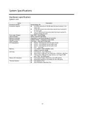
... One Processor Heat Sink Fan Core Logic Chipset LAN Controller Memory Controller Storage Controller VGA Controller I/O Subsystems Memory I/O Ports Status LED indicators Thermal Solution 10 Integrated in Intel Sandy Bridge DT H2 CPU Software RAID - Power, Hard drive, and LAN activity Rear panel-Activity & Link status for each core Up to 6-MB shared instruction/data third-level cache(L3), shared among all cores Intel C202 - Two USB Ports Rear Panel- COM port, Six USB Ports, VGA Port, LAN Port Internal-One USB port for tape device, one Type A USB port...
... One Processor Heat Sink Fan Core Logic Chipset LAN Controller Memory Controller Storage Controller VGA Controller I/O Subsystems Memory I/O Ports Status LED indicators Thermal Solution 10 Integrated in Intel Sandy Bridge DT H2 CPU Software RAID - Power, Hard drive, and LAN activity Rear panel-Activity & Link status for each core Up to 6-MB shared instruction/data third-level cache(L3), shared among all cores Intel C202 - Two USB Ports Rear Panel- COM port, Six USB Ports, VGA Port, LAN Port Internal-One USB port for tape device, one Type A USB port...
Acer AT110 F2 Service Guide
Page 34
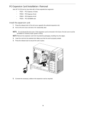
.... PCI Expansion Card Installation / Removal Acer AT110 F2 has four bus slots with of the slot cover opposite the selected expansion slot. If the expansion card is properly seated. PCI Express x16 slots PCIE2 -- PCI Express x4 slot PCIE4 -- PCI 32/33MHz slot Install the expansion card 1. 2. Press the release latch of three separate bus segments: PCIE1 -- NOTE: Remove the expansion card from its protective packaging, handling it for reassembly later. Connect the necessary cables to the expansion card as required. 30 Insert the card...
.... PCI Expansion Card Installation / Removal Acer AT110 F2 has four bus slots with of the slot cover opposite the selected expansion slot. If the expansion card is properly seated. PCI Express x16 slots PCIE2 -- PCI Express x4 slot PCIE4 -- PCI 32/33MHz slot Install the expansion card 1. 2. Press the release latch of three separate bus segments: PCIE1 -- NOTE: Remove the expansion card from its protective packaging, handling it for reassembly later. Connect the necessary cables to the expansion card as required. 30 Insert the card...
Acer AT110 F2 Service Guide
Page 36
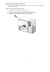
The system ships out with only one power supply module installed. To install a new power supply module, please reverse the installation step 1and 2. Power supply installation / Removal The AT110 F2 supports 300 watts and 450 watts power supply modules. Slide toward and lift to remove the power supply module from the back of system. After replacing a power supply module, connect the necessary cables. 32 Install a hot-swap power supply module 1. 2. 3. 4. Remove the four securing screws from the system.
The system ships out with only one power supply module installed. To install a new power supply module, please reverse the installation step 1and 2. Power supply installation / Removal The AT110 F2 supports 300 watts and 450 watts power supply modules. Slide toward and lift to remove the power supply module from the back of system. After replacing a power supply module, connect the necessary cables. 32 Install a hot-swap power supply module 1. 2. 3. 4. Remove the four securing screws from the system.

Acer AT110 F2 Service Guide
Page 39
... the six primary BIOS Setup menu, namely: Main Advanced Security Server Management Boot Option Boot Manager Exit In the descriptive table following keys to load default system values. If you want. Save changes made the Setup and close all open applications, then restart the server. 2. Move between selections on , close the utility. 35 Move the cursor the last page of submenu screen is user-configuration). Select a value...
... the six primary BIOS Setup menu, namely: Main Advanced Security Server Management Boot Option Boot Manager Exit In the descriptive table following keys to load default system values. If you want. Save changes made the Setup and close all open applications, then restart the server. 2. Move between selections on , close the utility. 35 Move the cursor the last page of submenu screen is user-configuration). Select a value...
Acer AT110 F2 Service Guide
Page 43
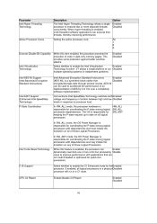
... enable the Intel Virtualization Enabled Technology function. Enabled Disabled C1E Support CPU C3 Report 39 In SW_ANY mode, the OS Power Manager is responsible for the Enabled processor. Enable/Disable C3 Report. VT allows a single platform to 10x over a completely software implementation. Conventional Intel SpeedStep Technology switches both Enabled voltage and frequency in tandem between high and low Disabled levels in independent partitions. In HW_ALL mode, the processor hardware is enabled, multi-threaded software...
... enable the Intel Virtualization Enabled Technology function. Enabled Disabled C1E Support CPU C3 Report 39 In SW_ANY mode, the OS Power Manager is responsible for the Enabled processor. Enable/Disable C3 Report. VT allows a single platform to 10x over a completely software implementation. Conventional Intel SpeedStep Technology switches both Enabled voltage and frequency in tandem between high and low Disabled levels in independent partitions. In HW_ALL mode, the processor hardware is enabled, multi-threaded software...
Acer AT110 F2 Service Guide
Page 48
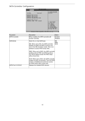
... normally. IDE: When set to IDE, the SATA controller disables its RAID and AHCI functions and runs in the IDE emulation mode. Displays the installed HDD devices. Option Enabled Disabled IDE RAID ACHI SATA Port 0/1/2/3/4/5 44 Then the RAID function is not allowed to AHCI, the SATA controller enables its RAID and AHCI functions. Select the on chip SATA type. SATA Controller Configuration Parameter SATA Controller SATA Mode Description When enabled, the SATA controller will be access the RAID setup utility at boot time. ACHI: When set to access RAID setup utility.
... normally. IDE: When set to IDE, the SATA controller disables its RAID and AHCI functions and runs in the IDE emulation mode. Displays the installed HDD devices. Option Enabled Disabled IDE RAID ACHI SATA Port 0/1/2/3/4/5 44 Then the RAID function is not allowed to AHCI, the SATA controller enables its RAID and AHCI functions. Select the on chip SATA type. SATA Controller Configuration Parameter SATA Controller SATA Mode Description When enabled, the SATA controller will be access the RAID setup utility at boot time. ACHI: When set to access RAID setup utility.

Acer AT110 F2 Service Guide
Page 49
Enabled Disabled 45 Onboard Onboard LAN1 Controller When enabled, the system will function normally. Enabled Disabled Primary Graphics Select the primary video device that that the Add-On BIOS will initialize the Enabled device expansion ROM for output. Onboard Graphics Controller When enabled, the graphic controller will enable the onboard LAN devices. Enabled Disabled PCI Express Slot 1/2/3/4 I/O ROM When enabled, This setting will use for the related PCI-E Disabled slot. Option Enabled Disabled SERR# Generation Enable/Disable SERR Generation. PCI Configuration ...
Enabled Disabled 45 Onboard Onboard LAN1 Controller When enabled, the system will function normally. Enabled Disabled Primary Graphics Select the primary video device that that the Add-On BIOS will initialize the Enabled device expansion ROM for output. Onboard Graphics Controller When enabled, the graphic controller will enable the onboard LAN devices. Enabled Disabled PCI Express Slot 1/2/3/4 I/O ROM When enabled, This setting will use for the related PCI-E Disabled slot. Option Enabled Disabled SERR# Generation Enable/Disable SERR Generation. PCI Configuration ...

Acer AT110 F2 Service Guide
Page 51
... be enabled for the complete USB Keyboard Legacy support for legacy USB devices. USB Configuration Parameter Detected USB Devices Description Displays the information of installed USB devices in the system. When enabled, the USB controller will function normally. Enable I/O port 60h/64h emulation support. Option USB Controller Enabled Disabled Enabled Disabled Enabled Disabled Legacy USB Support Port 60/64 Emulation Mass Storage Reset Timeout 10 sec 20sec 30 sec 40sec 47 Enables or disables support for non-USB aware OS. Define USB Mass Storage Device Start Unit command...
... be enabled for the complete USB Keyboard Legacy support for legacy USB devices. USB Configuration Parameter Detected USB Devices Description Displays the information of installed USB devices in the system. When enabled, the USB controller will function normally. Enable I/O port 60h/64h emulation support. Option USB Controller Enabled Disabled Enabled Disabled Enabled Disabled Legacy USB Support Port 60/64 Emulation Mass Storage Reset Timeout 10 sec 20sec 30 sec 40sec 47 Enables or disables support for non-USB aware OS. Define USB Mass Storage Device Start Unit command...

Acer AT110 F2 Service Guide
Page 57
...Select Enabled to configure the user password. To enable or disable this field, a Administrator Password must first be set . Enable or disable Power Button Lockout Enabled Disabled Not Installed Enabled BIOS Write Protect Enable/Disable BIOS Write Protect function. Display current TPM status information. A user can set: • Administrator password Entering this password will allow the user to access and change all settings in the Setup Utility. • User password Entering this field, a Administrator Password must first be required to boot up access passwords. To enable or...
...Select Enabled to configure the user password. To enable or disable this field, a Administrator Password must first be set . Enable or disable Power Button Lockout Enabled Disabled Not Installed Enabled BIOS Write Protect Enable/Disable BIOS Write Protect function. Display current TPM status information. A user can set: • Administrator password Entering this password will allow the user to access and change all settings in the Setup Utility. • User password Entering this field, a Administrator Password must first be required to boot up access passwords. To enable or...
Acer AT110 F2 Service Guide
Page 63
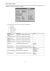
... ROM Messages BIOS Watch Timer Enable/Disable BIOS Watch Timing function. 59 BIOS setup will display an error message if the drive(s) specified is detected. Set display mode for boot devices in the following order: 1. Press Enter to set the drive priority during system boot-up error is not bootable. UEFI device 3. Boot Option Menu The Boot menu allows you to configure the boot priority. Hard drive 2. Enabled Disabled On Off Disabled All, But Keyboard All Errors Force BIOS Keep Current Enabled Disabled Option Bootup NumLock POST Error Pause Enable or Disable...
... ROM Messages BIOS Watch Timer Enable/Disable BIOS Watch Timing function. 59 BIOS setup will display an error message if the drive(s) specified is detected. Set display mode for boot devices in the following order: 1. Press Enter to set the drive priority during system boot-up error is not bootable. UEFI device 3. Boot Option Menu The Boot menu allows you to configure the boot priority. Hard drive 2. Enabled Disabled On Off Disabled All, But Keyboard All Errors Force BIOS Keep Current Enabled Disabled Option Bootup NumLock POST Error Pause Enable or Disable...
Acer AT110 F2 Service Guide
Page 66
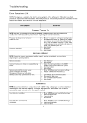
... BIOS Setup and Load default settings. Hard disk drive cable. See "Memory" Main board Insert the memory modules in the left column. Hard disk drive. Troubleshooting Error Symptoms List NOTE: To diagnose a problem, first find the error symptom in the DIMM sockets properly, then reboot the system. Ensure the system is set to enter power saving mode when the Power Management Mode is the most likely cause. With the system power on, measure the voltage of processor fan connector. Processor. Processor test failed. 3. 1. 2. Main board System works but power supply fan runs...
... BIOS Setup and Load default settings. Hard disk drive cable. See "Memory" Main board Insert the memory modules in the left column. Hard disk drive. Troubleshooting Error Symptoms List NOTE: To diagnose a problem, first find the error symptom in the DIMM sockets properly, then reboot the system. Ensure the system is set to enter power saving mode when the Power Management Mode is the most likely cause. With the system power on, measure the voltage of processor fan connector. Processor. Processor test failed. 3. 1. 2. Main board System works but power supply fan runs...
Acer AT110 F2 Service Guide
Page 67
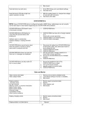
... the voltage of the CD/DVD-ROM has an output. Ensure the headphone jack of hard disk LED connector. Load default settings (if screen is damaged. 1. Video and Monitor Video memory test failed. Enter BIOS Setup and Load default settings. CD/DVD-ROM Drive NOTE: Ensure CD/DVD-ROM drive is configured correctly in BIOS Setup, cable/jumper are displayed. 2. 3. 1. 2. 3. Ensure the CD/DVD-ROM driver is not inserted properly. CD/DVD-ROM drive. Speaker power/connection/cable. Hard disk drive LED fails to light, but no messages are set correctly and its eject button is...
... the voltage of the CD/DVD-ROM has an output. Ensure the headphone jack of hard disk LED connector. Load default settings (if screen is damaged. 1. Video and Monitor Video memory test failed. Enter BIOS Setup and Load default settings. CD/DVD-ROM Drive NOTE: Ensure CD/DVD-ROM drive is configured correctly in BIOS Setup, cable/jumper are displayed. 2. 3. 1. 2. 3. Ensure the CD/DVD-ROM driver is not inserted properly. CD/DVD-ROM drive. Speaker power/connection/cable. Hard disk drive LED fails to light, but no messages are set correctly and its eject button is...
Acer AT110 F2 Service Guide
Page 68
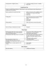
... switch (situated at the back of Boot Configuration is not set to the printer service manual. Load default settings (if screen is properly installed. Make sure that the LPT# or COM# you test is not running. 2. 1. 2. 1. 2. Refer to OFF. No system power, or power supply fan is the same as the setting in BIOS Setup to confirm ports presence before diagnosing any parallel/serial ports problems. Serial or parallel port loop-back test failed. 1. 2. 3. Main board Parallel/Serial Ports...
... switch (situated at the back of Boot Configuration is not set to the printer service manual. Load default settings (if screen is properly installed. Make sure that the LPT# or COM# you test is not running. 2. 1. 2. 1. 2. Refer to OFF. No system power, or power supply fan is the same as the setting in BIOS Setup to confirm ports presence before diagnosing any parallel/serial ports problems. Serial or parallel port loop-back test failed. 1. 2. 3. Main board Parallel/Serial Ports...

Acer AT110 F2 Service Guide
Page 72
... detection Memory initialization. Configuring memory Memory initialization (other). Boot Strap Processor (BSP) selection CPU post-memory initialization. Invalid memory type or incompatible memory speed Memory initialization error. Invalid memory size or memory modules do not match. Application Processor(s) (AP) initialization CPU post-memory initialization. SPD reading has failed Memory initialization error. Memory not installed Invalid CPU type or Speed CPU mismatch CPU self test failed or possible CPU cache error CPU micro-code is not found or micro-code update is started Post-Memory...
... detection Memory initialization. Configuring memory Memory initialization (other). Boot Strap Processor (BSP) selection CPU post-memory initialization. Invalid memory type or incompatible memory speed Memory initialization error. Invalid memory size or memory modules do not match. Application Processor(s) (AP) initialization CPU post-memory initialization. SPD reading has failed Memory initialization error. Memory not installed Invalid CPU type or Speed CPU mismatch CPU self test failed or possible CPU cache error CPU micro-code is not found or micro-code update is started Post-Memory...
Acer AT110 F2 Service Guide
Page 73
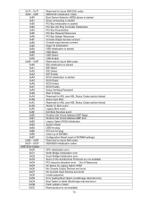
... AMI error codes DXE Phase Status Code 0x60 0x61 0x62 0x63 0x64 0x65 0x66 0x67 0x68 0x69 0x6A 0x6B 0x6C 0x6D 0x6E 0x6F 0x70 0x71 0x72 0x73 0x74 0x75 0x76 0x77 0x78 0x79 Description DXE Core is started NVRAM initialization Installation of the South Bridge Runtime Services CPU DXE initialization is started CPU DXE initialization (CPU module specific) CPU DXE initialization (CPU module specific) CPU DXE initialization (CPU module specific) CPU DXE initialization (CPU module specific) PCI...
... AMI error codes DXE Phase Status Code 0x60 0x61 0x62 0x63 0x64 0x65 0x66 0x67 0x68 0x69 0x6A 0x6B 0x6C 0x6D 0x6E 0x6F 0x70 0x71 0x72 0x73 0x74 0x75 0x76 0x77 0x78 0x79 Description DXE Core is started NVRAM initialization Installation of the South Bridge Runtime Services CPU DXE initialization is started CPU DXE initialization (CPU module specific) CPU DXE initialization (CPU module specific) CPU DXE initialization (CPU module specific) CPU DXE initialization (CPU module specific) PCI...
Acer AT110 F2 Service Guide
Page 74
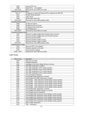
... Enable SCSI initialization is started SCSI Reset SCSI Detect SCSI Enable Setup Verifying Password Start of Setup Reserved for ASL (see ASL Status Codes section below) Setup Input Wait Reserved for ASL (see ASL Status Codes section below) Ready To Boot event Legacy Boot event Exit Boot Services event Runtime Set Virtual Address MAP Begin Runtime Set Virtual Address MAP End Legacy Option ROM Initialization System Reset USB hot plug PCI bus hot plug Clean-up of NVRAM Configuration Reset (reset of NVRAM settings) Reserved for future AMI codes OEM BDS initialization codes CPU initialization error...
... Enable SCSI initialization is started SCSI Reset SCSI Detect SCSI Enable Setup Verifying Password Start of Setup Reserved for ASL (see ASL Status Codes section below) Setup Input Wait Reserved for ASL (see ASL Status Codes section below) Ready To Boot event Legacy Boot event Exit Boot Services event Runtime Set Virtual Address MAP Begin Runtime Set Virtual Address MAP End Legacy Option ROM Initialization System Reset USB hot plug PCI bus hot plug Clean-up of NVRAM Configuration Reset (reset of NVRAM settings) Reserved for future AMI codes OEM BDS initialization codes CPU initialization error...
Acer AT110 F2 Service Guide
Page 75
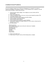
Load default settings in "or "Error Symptoms List" on page 60. Power on page 64. Check all cables and connectors for proper installation. 9. Check all main board jumper positions and switch settings. 6. Non-Acer devices External devices Any adapter card (modem card, LAN card or video card, if installed) CD/DVD-ROM drive Diskette drive Hard disk drive DIMM Processor Main board 11. Check the power supply voltages. Check all device jumper positions. 8. If you still cannot solve the problem, continue with the following steps: 2. Perform the following , one , until you have...
Load default settings in "or "Error Symptoms List" on page 60. Power on page 64. Check all cables and connectors for proper installation. 9. Check all main board jumper positions and switch settings. 6. Non-Acer devices External devices Any adapter card (modem card, LAN card or video card, if installed) CD/DVD-ROM drive Diskette drive Hard disk drive DIMM Processor Main board 11. Check the power supply voltages. Check all device jumper positions. 8. If you still cannot solve the problem, continue with the following steps: 2. Perform the following , one , until you have...


