
User Manual
Page 5
This server must be placed in electric shock and/or injury. Note: The grounding pin also provides good protection from the wall outlet and refer servicing to ...
This server must be placed in electric shock and/or injury. Note: The grounding pin also provides good protection from the wall outlet and refer servicing to ...

User Manual
Page 15
... 22 Turning off the system 23 3 System upgrades 25 Installation precautions 26 ESD precautions 26 Pre-installation instructions 26 Post-installation instructions 27 Opening the server 28 Configuring the storage devices 30 Accessing the drive bays 30 Hard disk drive configuration guidelines 30 Determining drive status 31 Removing and installing a 3.5" hard...
... 22 Turning off the system 23 3 System upgrades 25 Installation precautions 26 ESD precautions 26 Pre-installation instructions 26 Post-installation instructions 27 Opening the server 28 Configuring the storage devices 30 Accessing the drive bays 30 Hard disk drive configuration guidelines 30 Determining drive status 31 Removing and installing a 3.5" hard...

User Manual
Page 17
xvii Confirming loading of the operating system 116 Specific problems and corrective actions 117 Appendix A: Server management tools Server management overview RAID configuration utilities Intel onboard SATA RAID Creation Adaptec onboard SATA RAID Creation Configuring...Installing the system into the rack 133 135 137 138 139 Appendix C: Acer Smart Console Using Acer Smart Console Software requirements Accessing Acer Smart Console Acer Smart Console user interface System Information Server Health Configuration Remote Control Launch SOL Virtual Media Maintenance KVM function description Exit...
xvii Confirming loading of the operating system 116 Specific problems and corrective actions 117 Appendix A: Server management tools Server management overview RAID configuration utilities Intel onboard SATA RAID Creation Adaptec onboard SATA RAID Creation Configuring...Installing the system into the rack 133 135 137 138 139 Appendix C: Acer Smart Console Using Acer Smart Console Software requirements Accessing Acer Smart Console Acer Smart Console user interface System Information Server Health Configuration Remote Control Launch SOL Virtual Media Maintenance KVM function description Exit...
User Manual
Page 20
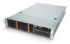
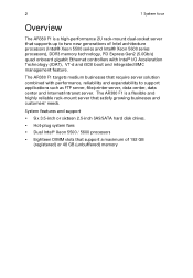
... / 5600 processors • Eighteen DIMM slots that require server solution combined with Intel® I/O Acceleration Technology (IOAT), VT-d and iSCSI boot and integrated BMC management feature. The AR380 F1 targets medium businesses that support a maximum of Intel architecture processors... Overview The AR380 F1 is a flexible and highly reliable rack-mount server that supports up to support applications such as FTP server, file/printer server, data center, data center and Internet/Intranet server. The AR380 F1 is a high-performance 2U rack-mount dual-socket server that satisfy ...
... / 5600 processors • Eighteen DIMM slots that require server solution combined with Intel® I/O Acceleration Technology (IOAT), VT-d and iSCSI boot and integrated BMC management feature. The AR380 F1 targets medium businesses that support a maximum of Intel architecture processors... Overview The AR380 F1 is a flexible and highly reliable rack-mount server that supports up to support applications such as FTP server, file/printer server, data center, data center and Internet/Intranet server. The AR380 F1 is a high-performance 2U rack-mount dual-socket server that satisfy ...

User Manual
Page 25
7 Rear panel No. 1 2 3 4 5 6 7 8-11 12 13 -14 15 16-18 19 Component Power supply modules PS/2 mouse port PS/2 keyboard port Server management port (RJ-45) (10/100 Mbps) USB 2.0 ports COM port Monitor port Gigabit LAN1 - 4 ports (10/100/1000 Mbps) Flex I/O expansion slot Full-height PCI Express 2.0 x8 (x4 link) expansion slots Full-height PCI Express 2.0 x16 (x8 link) expansion slot Low-profile PCI Express 2.0 x8 (x4 link) expansion slots System ID indicator
7 Rear panel No. 1 2 3 4 5 6 7 8-11 12 13 -14 15 16-18 19 Component Power supply modules PS/2 mouse port PS/2 keyboard port Server management port (RJ-45) (10/100 Mbps) USB 2.0 ports COM port Monitor port Gigabit LAN1 - 4 ports (10/100/1000 Mbps) Flex I/O expansion slot Full-height PCI Express 2.0 x8 (x4 link) expansion slots Full-height PCI Express 2.0 x16 (x8 link) expansion slot Low-profile PCI Express 2.0 x8 (x4 link) expansion slots System ID indicator

User Manual
Page 37
Front connections Rear connections Note: Consult the operating system manual for specific connection instructions on 100-127/200-240 VAC only. Refer to the illustration below for information on how to the system. Do not connect the system to an incorrect voltage source. The server operates on the peripherals you want to connect to configure the network setup. 19 Connecting peripherals Caution!
Front connections Rear connections Note: Consult the operating system manual for specific connection instructions on 100-127/200-240 VAC only. Refer to the illustration below for information on how to the system. Do not connect the system to an incorrect voltage source. The server operates on the peripherals you want to connect to configure the network setup. 19 Connecting peripherals Caution!
User Manual
Page 40
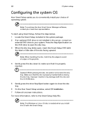
... careful not to close the disc tray. 6 On the Acer Smart Setup window, select OS Installation. 7 Follow all onscreen instructions. To start using Smart Setup, follow the steps below. 1 Locate the Smart Setup included in the server, connect an external DVD drive to your system. Note: ...installed in the system package. 2 If an optional DVD drive is needed when you to conveniently install your local Acer representative. Note: To purchase the Acer Smart Server Manager software, contact your choice of the disc facing upward. Make sure that it is properly inserted before closing the...
... careful not to close the disc tray. 6 On the Acer Smart Setup window, select OS Installation. 7 Follow all onscreen instructions. To start using Smart Setup, follow the steps below. 1 Locate the Smart Setup included in the server, connect an external DVD drive to your system. Note: ...installed in the system package. 2 If an optional DVD drive is needed when you to conveniently install your local Acer representative. Note: To purchase the Acer Smart Server Manager software, contact your choice of the disc facing upward. Make sure that it is properly inserted before closing the...

User Manual
Page 41
... applies to the related user documentation. For further operating system shutdown procedures, refer to a system running the Windows operating system. To turn off the server - 23 Turning off the system There are two ways to turn off the system via software: 1 Press + + on the attached keyboard or ...click Start on the Windows taskbar. 2 Select Shut Down. 3 Select Shut down from the drop-down the server using the software, press and hold the power button for at least four seconds. To turn off the system via hardware. Quickly pressing the button...
... applies to the related user documentation. For further operating system shutdown procedures, refer to a system running the Windows operating system. To turn off the server - 23 Turning off the system There are two ways to turn off the system via software: 1 Press + + on the attached keyboard or ...click Start on the Windows taskbar. 2 Select Shut Down. 3 Select Shut down from the drop-down the server using the software, press and hold the power button for at least four seconds. To turn off the system via hardware. Quickly pressing the button...

User Manual
Page 44
...(ESD) can damage the processor, disk drives, expansion boards, mainboard, memory modules and other server components. Pre-installation instructions Perform the steps below before you open the server or before you start installing components may cause serious damage. If a wrist strap is not... instructions. Always observe the following sections unless you read the following sections. 26 3 System upgrades Installation precautions Before you install any server component, we recommend that you are ready to install it. • Do not touch the component pins, leads, or circuitry....
...(ESD) can damage the processor, disk drives, expansion boards, mainboard, memory modules and other server components. Pre-installation instructions Perform the steps below before you open the server or before you start installing components may cause serious damage. If a wrist strap is not... instructions. Always observe the following sections unless you read the following sections. 26 3 System upgrades Installation precautions Before you install any server component, we recommend that you are ready to install it. • Do not touch the component pins, leads, or circuitry....

User Manual
Page 45
Post-installation instructions Perform the steps below after installing a server component. 1 See to it that have been previously removed. 3 Reinstall the top cover. 4 Reconnect the necessary cables. 5 Turn on page 43. 6 Follow the ESD precautions described in this section when handling a server component. 27 4 Place the system unit on a flat, stable surface. 5 Open the system according to the described step-by-step instructions. 2 Reinstall all components or cable that all components are installed according to the instructions on the system.
Post-installation instructions Perform the steps below after installing a server component. 1 See to it that have been previously removed. 3 Reinstall the top cover. 4 Reconnect the necessary cables. 5 Turn on page 43. 6 Follow the ESD precautions described in this section when handling a server component. 27 4 Place the system unit on a flat, stable surface. 5 Open the system according to the described step-by-step instructions. 2 Reinstall all components or cable that all components are installed according to the instructions on the system.

User Manual
Page 46
... cover toward the rear of the chassis. 3 Lift the cover off the system and all peripherals connected to it. Refer to open the server before you have turned off the chassis. 4 Put the top cover aside for instructions. You need to the following sections for reinstallation later.... 28 Opening the server 3 System upgrades Caution: Before you proceed, make sure that you can install additional components or access the system's internal components. Read the "...
... cover toward the rear of the chassis. 3 Lift the cover off the system and all peripherals connected to it. Refer to open the server before you have turned off the chassis. 4 Put the top cover aside for instructions. You need to the following sections for reinstallation later.... 28 Opening the server 3 System upgrades Caution: Before you proceed, make sure that you can install additional components or access the system's internal components. Read the "...

User Manual
Page 48
... must remain in the following Accessing the drive bays Since SAS/SATA drives have hot-plug capability, you use must have RAID support to the server. To purchase a SAS or SATA HDD, contact your local representative. • Before removing a hard disk drive, make sure no cables touch the backplane. An optional...
... must remain in the following Accessing the drive bays Since SAS/SATA drives have hot-plug capability, you use must have RAID support to the server. To purchase a SAS or SATA HDD, contact your local representative. • Before removing a hard disk drive, make sure no cables touch the backplane. An optional...
User Manual
Page 59
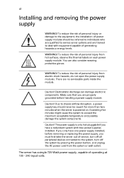
...cause the system to the equipment, the installation of power supply modules should never be referred to individuals who are qualified to service server systems and are trained to the system, turn off the system by pressing the power button, and unplug the AC power cord ... supply, you have one power supply installed, before handling a power supply module. Electrostatic discharge can also consider wearing protective gloves. Caution! The server has a single 720-Watt power supply, capable of personal injury from electric shock hazards, do not open the power supply modules. To reduce ...
...cause the system to the equipment, the installation of power supply modules should never be referred to individuals who are qualified to service server systems and are trained to the system, turn off the system by pressing the power button, and unplug the AC power cord ... supply, you have one power supply installed, before handling a power supply module. Electrostatic discharge can also consider wearing protective gloves. Caution! The server has a single 720-Watt power supply, capable of personal injury from electric shock hazards, do not open the power supply modules. To reduce ...

User Manual
Page 60
... Power supply failure If the power supply unit fails, the system will shut down and you will need to release the power supply module from Acer. Replacement units can be ordered directly from the chassis. (2) Use the handle to pull the failed power supply module out of the chassis and then... the power supply release latch to replace the power supply unit. Replacing the power supply Press the main power button on the front of the server. 3 Install a new power supply module with the exact same model.
... Power supply failure If the power supply unit fails, the system will shut down and you will need to release the power supply module from Acer. Replacement units can be ordered directly from the chassis. (2) Use the handle to pull the failed power supply module out of the chassis and then... the power supply release latch to replace the power supply unit. Replacing the power supply Press the main power button on the front of the server. 3 Install a new power supply module with the exact same model.

User Manual
Page 61
Removing and installing the air duct Caution: Always operate your server with the air duct installed to ensure reliable and continued operation. Installing the air duct 1 Perform the pre-installation instructions described on button. 43 4 Push the new power supply module into the power bay until it clicks into place. 5 Plug the AC power cord back into the module and power up the server by pushing the power on page 26. Removing the air duct 1 Perform the pre-installation instructions described on page 26. 2 Lift the air duct from the chassis.
Removing and installing the air duct Caution: Always operate your server with the air duct installed to ensure reliable and continued operation. Installing the air duct 1 Perform the pre-installation instructions described on button. 43 4 Push the new power supply module into the power bay until it clicks into place. 5 Plug the AC power cord back into the module and power up the server by pushing the power on page 26. Removing the air duct 1 Perform the pre-installation instructions described on page 26. 2 Lift the air duct from the chassis.

User Manual
Page 67
... stepping and frequency specifications as the default processor. • Handle the processor and the heat sink carefully. 49 Upgrading the processor Processor configuration guidelines The server supports two LGA 1366 processor sockets supporting dualcore or quad-core Intel Xeon processors. The supplied processors may prevent the system from functioning properly. If...
... stepping and frequency specifications as the default processor. • Handle the processor and the heat sink carefully. 49 Upgrading the processor Processor configuration guidelines The server supports two LGA 1366 processor sockets supporting dualcore or quad-core Intel Xeon processors. The supplied processors may prevent the system from functioning properly. If...

User Manual
Page 77
59 Installing an expansion card Your server has a preinstalled riser card designed specifically for use in the direction shown below (1). 3 Remove the slot shield (2). Depending on the type of riser card installed, you can install the following expansion cards: • Left riser card (pre-installed) • One Acer Flex I/O (PCI-E 2.0 x8) slot •...
59 Installing an expansion card Your server has a preinstalled riser card designed specifically for use in the direction shown below (1). 3 Remove the slot shield (2). Depending on the type of riser card installed, you can install the following expansion cards: • Left riser card (pre-installed) • One Acer Flex I/O (PCI-E 2.0 x8) slot •...
User Manual
Page 84
... setup navigation process. Changing configuration data The configuration data that can access the other setup screens. As the memory is an area reserved for your server. This chapter describes the basic navigation of the BIOS setup utility hotkeys can be configured by pressing at the left frame, it . The Main BIOS... BIOS is booting up. These keys include , , , and arrow keys. The left frame displays all the options that determines the system parameters may be configured. Acer retains the option to enter the BIOS setup utility main menu.
... setup navigation process. Changing configuration data The configuration data that can access the other setup screens. As the memory is an area reserved for your server. This chapter describes the basic navigation of the BIOS setup utility hotkeys can be configured by pressing at the left frame, it . The Main BIOS... BIOS is booting up. These keys include , , , and arrow keys. The left frame displays all the options that determines the system parameters may be configured. Acer retains the option to enter the BIOS setup utility main menu.

User Manual
Page 115
...will be assigned an IP address. Select Static (Static Allocation) to allow a client (computer or device) to obtain an IP address from a DHCP server that are manually entered (such as by a network administrator). Select DHCP (Dynamic Host Configuration Protocol) to allow the host... server to a client computer or network device. 97 Product Information This submenu displays the following product information. • System Product Name • System Serial Number...
...will be assigned an IP address. Select Static (Static Allocation) to allow a client (computer or device) to obtain an IP address from a DHCP server that are manually entered (such as by a network administrator). Select DHCP (Dynamic Host Configuration Protocol) to allow the host... server to a client computer or network device. 97 Product Information This submenu displays the following product information. • System Product Name • System Serial Number...

User Manual
Page 132
and connected to a NEMA 5-15R outlet for 100120 V or a NEMA 6-15R outlet for the problem you press the system power button to turn the server on (power on add-in boards sharing the same interrupt). If applicable, ensure that comes with the tested components lists? • Are all internal cables ...
and connected to a NEMA 5-15R outlet for 100120 V or a NEMA 6-15R outlet for the problem you press the system power button to turn the server on (power on add-in boards sharing the same interrupt). If applicable, ensure that comes with the tested components lists? • Are all internal cables ...


