User Manual
Page 13
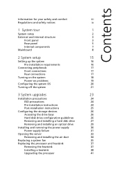
... installing a hard disk drive 27 Removing and installing an optical drive 29 Installing and removing the power supply 30 Power supply failure 31 Opening the server 33 Removing and installing the air duct 34 Replacing a system fan 35 Replacing the processor and heatsink 37 Removing the heatsink 37 Installing a heatsink 38...
... installing a hard disk drive 27 Removing and installing an optical drive 29 Installing and removing the power supply 30 Power supply failure 31 Opening the server 33 Removing and installing the air duct 34 Replacing a system fan 35 Replacing the processor and heatsink 37 Removing the heatsink 37 Installing a heatsink 38...
User Manual
Page 14
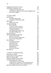
... Upgrading the system memory 44 Installing an expansion card 52 Installing a PCI Express card 52 Installing the right riser card and the Gigabit dual port server adapter 54 4 System BIOS 57 Introduction 58 The BIOS setup utility 58 Changing configuration data 58 Main setup 59 System Overview 59 Advanced Settings 61...
... Upgrading the system memory 44 Installing an expansion card 52 Installing a PCI Express card 52 Installing the right riser card and the Gigabit dual port server adapter 54 4 System BIOS 57 Introduction 58 The BIOS setup utility 58 Changing configuration data 58 Main setup 59 System Overview 59 Advanced Settings 61...

User Manual
Page 15
... Rack installation information System rack installation Vertical mounting hole pattern Installing the system into the rack Appendix C: Acer Smart Console Using Acer Smart Console Software requirements Accessing Acer Smart Console Acer Smart Console user interface System Information Server Health Configuration Remote Control Launch SOL Virtual Media Maintenance KVM function description Exit Index xv 97 98...
... Rack installation information System rack installation Vertical mounting hole pattern Installing the system into the rack Appendix C: Acer Smart Console Using Acer Smart Console Software requirements Accessing Acer Smart Console Acer Smart Console user interface System Information Server Health Configuration Remote Control Launch SOL Virtual Media Maintenance KVM function description Exit Index xv 97 98...

User Manual
Page 18
2 1 System tour System notes The AR160 is powered by an 80 Plus Gold power supply unit for RAID 0, 1, 5 or 10. The server has an integrated dual-port Gigabit Ethernet which supports Intel I /O expansion, Trusted Platform Module (TPM) 1.2, and includes a host of server management tools. The serverboard supports DDR3 memory, PCI Express 2.0, Flex I /O Acceleration Technology...
2 1 System tour System notes The AR160 is powered by an 80 Plus Gold power supply unit for RAID 0, 1, 5 or 10. The server has an integrated dual-port Gigabit Ethernet which supports Intel I /O expansion, Trusted Platform Module (TPM) 1.2, and includes a host of server management tools. The serverboard supports DDR3 memory, PCI Express 2.0, Flex I /O Acceleration Technology...

User Manual
Page 21
Component 1 Power socket 2 PS/2 mouse port 3 Server management port (RJ-45) (10/100 Mbps) 4 Low-profile PCI Express 2.0 x8 expansion slot 5 Full-height PCI Express 2.0 x16 expansion slot 6 Full-height PCI Express 2.0 x8 Flex I/O expansion slot 7 System ID indicator 8 Gigabit LAN ports (10/100/1000 Mbps) 9 Monitor port 10 COM port 11 USB 2.0 ports 12 PS/2 keyboard port 5 Rear panel No.
Component 1 Power socket 2 PS/2 mouse port 3 Server management port (RJ-45) (10/100 Mbps) 4 Low-profile PCI Express 2.0 x8 expansion slot 5 Full-height PCI Express 2.0 x16 expansion slot 6 Full-height PCI Express 2.0 x8 Flex I/O expansion slot 7 System ID indicator 8 Gigabit LAN ports (10/100/1000 Mbps) 9 Monitor port 10 COM port 11 USB 2.0 ports 12 PS/2 keyboard port 5 Rear panel No.

User Manual
Page 33
Front connections Rear connections Note: Consult the operating system manual for specific connection instructions on 100-127/200-240 VAC only. The server operates on the peripherals you want to connect to the system. Do not connect the system to configure the network setup. Refer to the illustration below for information on how to an incorrect voltage source. 17 Connecting peripherals Caution!
Front connections Rear connections Note: Consult the operating system manual for specific connection instructions on 100-127/200-240 VAC only. The server operates on the peripherals you want to connect to the system. Do not connect the system to configure the network setup. Refer to the illustration below for information on how to an incorrect voltage source. 17 Connecting peripherals Caution!

User Manual
Page 36
Note: The Windows or Linux OS disc is properly inserted before closing the disc tray. Note: To purchase the Acer Smart Server Manager software, contact your system. Press the Stop/Eject button on the DVD drive to make sure that the disc is needed when you to ...conveniently install your choice of the disc facing upward. Make sure that it is not installed in the server, connect an external DVD drive to close the disc tray. 6 On the Acer Smart Setup window, select OS Installation. 7 Follow all onscreen instructions. 20 2 System setup Configuring the system OS...
Note: The Windows or Linux OS disc is properly inserted before closing the disc tray. Note: To purchase the Acer Smart Server Manager software, contact your system. Press the Stop/Eject button on the DVD drive to make sure that the disc is needed when you to ...conveniently install your choice of the disc facing upward. Make sure that it is not installed in the server, connect an external DVD drive to close the disc tray. 6 On the Acer Smart Setup window, select OS Installation. 7 Follow all onscreen instructions. 20 2 System setup Configuring the system OS...

User Manual
Page 37
... + + on the attached keyboard or click Start on the Windows taskbar. 2 Select Shut Down. 3 Select Shut down from the drop-down the server using the software, press and hold the power button for at least four seconds. For further operating system shutdown procedures, refer to a system running the... Windows operating system. Quickly pressing the button may put the server in a Suspend mode only. To turn off the server - 21 Turning off the system There are two ways to turn off the system via hardware: If you cannot ...
... + + on the attached keyboard or click Start on the Windows taskbar. 2 Select Shut Down. 3 Select Shut down from the drop-down the server using the software, press and hold the power button for at least four seconds. For further operating system shutdown procedures, refer to a system running the... Windows operating system. Quickly pressing the button may put the server in a Suspend mode only. To turn off the server - 21 Turning off the system There are two ways to turn off the system via hardware: If you cannot ...

User Manual
Page 40
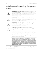
... it . 2 Unplug all cables from the power outlets. 3 Disconnect all the peripherals connected to it to properly turn off the server before you are a qualified service technician. 1 Turn off the system and all telecommunication cables from its protective packaging until you remove ...or replace any component: Warning! Always observe the following sections. Pre-installation instructions Perform the steps below before you open the server or before you start installing components may cause serious damage. Failure to a metal part of nonconductive materials, such as ordinary ...
... it . 2 Unplug all cables from the power outlets. 3 Disconnect all the peripherals connected to it to properly turn off the server before you are a qualified service technician. 1 Turn off the system and all telecommunication cables from its protective packaging until you remove ...or replace any component: Warning! Always observe the following sections. Pre-installation instructions Perform the steps below before you open the server or before you start installing components may cause serious damage. Failure to a metal part of nonconductive materials, such as ordinary ...

User Manual
Page 41
Post-installation instructions Perform the steps below after installing a server component. 1 See to it that have been previously removed. 3 Reinstall the top cover. 4 Reconnect the necessary cables. 5 Turn on page 33. 6 Follow the ESD precautions described in this section when handling a server component. 25 4 Place the system unit on a flat, stable surface. 5 Open the system according to the described step-by-step instructions. 2 Reinstall all components or cable that all components are installed according to the instructions on the system.
Post-installation instructions Perform the steps below after installing a server component. 1 See to it that have been previously removed. 3 Reinstall the top cover. 4 Reconnect the necessary cables. 5 Turn on page 33. 6 Follow the ESD precautions described in this section when handling a server component. 25 4 Place the system unit on a flat, stable surface. 5 Open the system according to the described step-by-step instructions. 2 Reinstall all components or cable that all components are installed according to the instructions on the system.

User Manual
Page 42
... support to enable the hot-plug capability of the chassis or power down the system to install or replace SAS/SATA drives. Proceed to the server. Hard disk drive configuration guidelines Observe these guidelines when replacing or installing a hard disk drive. • Use only qualified SAS or SATA HDDs. 26 3 System...
... support to enable the hot-plug capability of the chassis or power down the system to install or replace SAS/SATA drives. Proceed to the server. Hard disk drive configuration guidelines Observe these guidelines when replacing or installing a hard disk drive. • Use only qualified SAS or SATA HDDs. 26 3 System...
User Manual
Page 46
...five minutes might cause the system to chassis airflow disruption, a power supply bay should be vacant for more than two minutes when the server is only hot-pluggable if you only have a redundant system with equipment capable of power supply modules should never be referred to individuals ...who are qualified to service server systems and are no serviceable parts inside the module. There are trained to the system, turn off the system by pressing the power ...
...five minutes might cause the system to chassis airflow disruption, a power supply bay should be vacant for more than two minutes when the server is only hot-pluggable if you only have a redundant system with equipment capable of power supply modules should never be referred to individuals ...who are qualified to service server systems and are no serviceable parts inside the module. There are trained to the system, turn off the system by pressing the power ...

User Manual
Page 47
Replacement units can be ordered directly from the chassis. (2) Use the handle to pull the failed power supply module out of the server. 3 Install a new power supply module with the exact same model. Replacing the power supply Press the main power button on the front of the chassis ... Power supply failure If the power supply unit fails, the system will shut down and you will need to release the power supply module from Acer.
Replacement units can be ordered directly from the chassis. (2) Use the handle to pull the failed power supply module out of the server. 3 Install a new power supply module with the exact same model. Replacing the power supply Press the main power button on the front of the chassis ... Power supply failure If the power supply unit fails, the system will shut down and you will need to release the power supply module from Acer.

User Manual
Page 48
32 3 System upgrades 4 Push the new power supply module into the power bay until it clicks into place. 5 Plug the AC power cord back into the module and power up the server by pushing the power on button.
32 3 System upgrades 4 Push the new power supply module into the power bay until it clicks into place. 5 Plug the AC power cord back into the module and power up the server by pushing the power on button.

User Manual
Page 49
... peripherals connected to it. Removing the top cover Note: Observe the ESD precautions and pre-installation instructions described on page 24. Refer to open the server before you have turned off the chassis. 4 Put the top cover aside for instructions. You need to the following sections for reinstallation later. Before you...
... peripherals connected to it. Removing the top cover Note: Observe the ESD precautions and pre-installation instructions described on page 24. Refer to open the server before you have turned off the chassis. 4 Put the top cover aside for instructions. You need to the following sections for reinstallation later. Before you...

User Manual
Page 50
... the air duct to ensure reliable and continued operation. Installing the air duct 1 Perform the pre-installation instructions described on page 24. Always operate your server with the slots on the chassis. (2) Slide the top cover toward the front of the chassis until it is fully closed. 34 3 System upgrades Installing...
... the air duct to ensure reliable and continued operation. Installing the air duct 1 Perform the pre-installation instructions described on page 24. Always operate your server with the slots on the chassis. (2) Slide the top cover toward the front of the chassis until it is fully closed. 34 3 System upgrades Installing...

User Manual
Page 57
... lift the load lever. (3) Open the retention plate to either may be populated. Replacing the processor Warning! 41 Upgrading the processor Processor configuration guidelines The server supports two LGA 1366 processor sockets supporting dualcore or quad-core Intel Xeon processors. Damage to expose the socket body. The supplied processors may prevent...
... lift the load lever. (3) Open the retention plate to either may be populated. Replacing the processor Warning! 41 Upgrading the processor Processor configuration guidelines The server supports two LGA 1366 processor sockets supporting dualcore or quad-core Intel Xeon processors. Damage to expose the socket body. The supplied processors may prevent...

User Manual
Page 60
... upgrades Upgrading the system memory System memory interface Each processor has three memory channels (1, 2 and 3 ) and each channel should be used. • For a single-processor server configuration, install the processor to CPU1 socket and the memory modules in slots P1DIMM 1A to P1DIMM 3B. • If there is a processor installed in...
... upgrades Upgrading the system memory System memory interface Each processor has three memory channels (1, 2 and 3 ) and each channel should be used. • For a single-processor server configuration, install the processor to CPU1 socket and the memory modules in slots P1DIMM 1A to P1DIMM 3B. • If there is a processor installed in...

User Manual
Page 68
52 3 System upgrades Installing an expansion card Your server has a preinstalled riser card designed specifically for use in the direction shown below. 3 Remove the PCI slot shield. Depending on the type of riser card ... card (pre-installed) • PCI Express 2.0 x16 (full-height) • 8-port 3Gb/s SAS RAID Flex I/O Adapter • Right riser card (optional) • Gigabit Dual Port Server Adapter (low-profile) Installing a PCI Express card 1 Remove the screw that secures the left PCI expansion slot shield to the...
52 3 System upgrades Installing an expansion card Your server has a preinstalled riser card designed specifically for use in the direction shown below. 3 Remove the PCI slot shield. Depending on the type of riser card ... card (pre-installed) • PCI Express 2.0 x16 (full-height) • 8-port 3Gb/s SAS RAID Flex I/O Adapter • Right riser card (optional) • Gigabit Dual Port Server Adapter (low-profile) Installing a PCI Express card 1 Remove the screw that secures the left PCI expansion slot shield to the...

User Manual
Page 70
Installing the right riser card and the Gigabit dual port server adapter Perform the following steps: 1 Insert the right riser card into the PCI expansion slot. 54 3 System upgrades 6 Connect the appropriate cables to the card (SAS card illustration shown below).
Installing the right riser card and the Gigabit dual port server adapter Perform the following steps: 1 Insert the right riser card into the PCI expansion slot. 54 3 System upgrades 6 Connect the appropriate cables to the card (SAS card illustration shown below).


