User Manual
Page 13
...Front connections 17 Rear connections 17 Turning on the system 18 Power-on problems 19 Configuring the system OS 20 Turning off the system 21 3 System upgrades 23 Installation precautions 24 ESD precautions 24 Pre-installation instructions 24 Post-installation instructions 25 Configuring the storage devices 26 Accessing the drive bays 26 Hard disk drive configuration guidelines 26 Removing and installing a hard disk drive 27 Removing and installing an optical drive 29 Installing and removing the power supply 30 Power supply failure 31 Opening the server 33...
...Front connections 17 Rear connections 17 Turning on the system 18 Power-on problems 19 Configuring the system OS 20 Turning off the system 21 3 System upgrades 23 Installation precautions 24 ESD precautions 24 Pre-installation instructions 24 Post-installation instructions 25 Configuring the storage devices 26 Accessing the drive bays 26 Hard disk drive configuration guidelines 26 Removing and installing a hard disk drive 27 Removing and installing an optical drive 29 Installing and removing the power supply 30 Power supply failure 31 Opening the server 33...
User Manual
Page 14
...port server adapter 54 4 System BIOS 57 Introduction 58 The BIOS setup utility 58 Changing configuration data 58 Main setup 59 System Overview 59 Advanced Settings 61 Boot Features 61 Processor & Clock Options 62 Advanced Chipset Control 64 Trusted Computing 74 View BMC System Event Log 75 Set LAN Configuration 76 Security Settings 77 System Management Settings 78 System Information 79 Remote Access Configuration 80 Event Log Configuration 81 Boot Settings 82 Boot Device Priority 82 Hard Disk Drives 82 Network Drives 83 Removable Drives 83 CD/DVD...
...port server adapter 54 4 System BIOS 57 Introduction 58 The BIOS setup utility 58 Changing configuration data 58 Main setup 59 System Overview 59 Advanced Settings 61 Boot Features 61 Processor & Clock Options 62 Advanced Chipset Control 64 Trusted Computing 74 View BMC System Event Log 75 Set LAN Configuration 76 Security Settings 77 System Management Settings 78 System Information 79 Remote Access Configuration 80 Event Log Configuration 81 Boot Settings 82 Boot Device Priority 82 Hard Disk Drives 82 Network Drives 83 Removable Drives 83 CD/DVD...

User Manual
Page 15
Appendix A Server management tools Server management overview RAID configuration utilities Intel onboard SATA RAID Creation Adaptec onboard SATA RAID Creation External SATA RAID Creation Appendix B Rack mount configuration Rack installation information System rack installation Vertical mounting hole pattern Installing the system into the rack Appendix C: Acer Smart Console Using Acer Smart Console Software requirements Accessing Acer Smart Console Acer Smart Console user interface System Information Server Health Configuration Remote Control Launch SOL Virtual Media Maintenance KVM function ...
Appendix A Server management tools Server management overview RAID configuration utilities Intel onboard SATA RAID Creation Adaptec onboard SATA RAID Creation External SATA RAID Creation Appendix B Rack mount configuration Rack installation information System rack installation Vertical mounting hole pattern Installing the system into the rack Appendix C: Acer Smart Console Using Acer Smart Console Software requirements Accessing Acer Smart Console Acer Smart Console user interface System Information Server Health Configuration Remote Control Launch SOL Virtual Media Maintenance KVM function ...

User Manual
Page 42
... cables touch the backplane. An optional optical drive can also be installed in the chassis to four 3.5-inch hot-plug SAS/SATA hard disk drives. Hard disk drive configuration guidelines Observe these guidelines when replacing or installing a hard disk drive. • Use only qualified SAS or SATA HDDs. Caution! Also, regardless of how many SATA drives are installed, all important system files. • Check hard disk drive status by checking the status LED indicators on the HDD carrier. • The hard disk drive carriers must have RAID support to enable...
... cables touch the backplane. An optional optical drive can also be installed in the chassis to four 3.5-inch hot-plug SAS/SATA hard disk drives. Hard disk drive configuration guidelines Observe these guidelines when replacing or installing a hard disk drive. • Use only qualified SAS or SATA HDDs. Caution! Also, regardless of how many SATA drives are installed, all important system files. • Check hard disk drive status by checking the status LED indicators on the HDD carrier. • The hard disk drive carriers must have RAID support to enable...
User Manual
Page 46
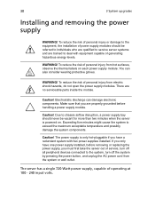
... have one power supply installed, before removing or replacing the power supply, you must first take the server out of personal injury from hot surfaces, observe the thermal labels on . 30 3 System upgrades Installing and removing the power supply WARNING! To reduce the risk of service, turn off the system by pressing the power button, and unplug the AC power cord from electric shock hazards, do not open the power supply modules. Exceeding five...
... have one power supply installed, before removing or replacing the power supply, you must first take the server out of personal injury from hot surfaces, observe the thermal labels on . 30 3 System upgrades Installing and removing the power supply WARNING! To reduce the risk of service, turn off the system by pressing the power button, and unplug the AC power cord from electric shock hazards, do not open the power supply modules. Exceeding five...

User Manual
Page 51
... of the fans has failed. Allow it to cool off first before handling. 2 Remove the top chassis cover while the system is on. To replace a fan module: 1 Perform the pre-installation instructions described on the chassis. Do not pinch or unplug cables that the tabs on the air duct align with the slots on page 24. Caution! The system fan becomes very hot when the...
... of the fans has failed. Allow it to cool off first before handling. 2 Remove the top chassis cover while the system is on. To replace a fan module: 1 Perform the pre-installation instructions described on the chassis. Do not pinch or unplug cables that the tabs on the air duct align with the slots on page 24. Caution! The system fan becomes very hot when the...

User Manual
Page 68
...) • 8-port 3Gb/s SAS RAID Flex I/O Adapter • Right riser card (optional) • Gigabit Dual Port Server Adapter (low-profile) Installing a PCI Express card 1 Remove the screw that secures the left PCI expansion slot shield to the server. 2 Slide the bolts to move the shield lock in the 1U rackmount chassis. 52 3 System upgrades Installing an expansion card Your server has a preinstalled riser card designed specifically for use in the direction shown below. 3 Remove the PCI slot shield.
...) • 8-port 3Gb/s SAS RAID Flex I/O Adapter • Right riser card (optional) • Gigabit Dual Port Server Adapter (low-profile) Installing a PCI Express card 1 Remove the screw that secures the left PCI expansion slot shield to the server. 2 Slide the bolts to move the shield lock in the 1U rackmount chassis. 52 3 System upgrades Installing an expansion card Your server has a preinstalled riser card designed specifically for use in the direction shown below. 3 Remove the PCI slot shield.
User Manual
Page 77
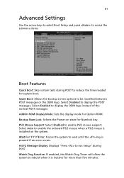
... instead of the normal POST messages. Watch Dog Function: If enabled, the Watch Dog Timer will allow the system to reduce the time needed for system boot. 61 Advanced Settings Use the arrow keys to select Boot Setup and press to access the submenu items: Boot Features Quick Boot: Skip certain tests during POST. Select Disabled to wait until the key is installed on state for Option ROM.
... instead of the normal POST messages. Watch Dog Function: If enabled, the Watch Dog Timer will allow the system to reduce the time needed for system boot. 61 Advanced Settings Use the arrow keys to select Boot Setup and press to access the submenu items: Boot Features Quick Boot: Skip certain tests during POST. Select Disabled to wait until the key is installed on state for Option ROM.
User Manual
Page 78
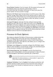
... power button for the system power to be turned on the motherboard. Select Last State to allow the BIOS to automatically configure the CPU Ratio based on the processor installed on after a power outage. The submenu also allows you press the power button. Interrupt 19 Capture: Interrupt 19 is only available if supported by the components. Processor & Clock Options This submenu displays the status of the processor as detected...
... power button for the system power to be turned on the motherboard. Select Last State to allow the BIOS to automatically configure the CPU Ratio based on the processor installed on after a power outage. The submenu also allows you press the power button. Interrupt 19 Capture: Interrupt 19 is only available if supported by the components. Processor & Clock Options This submenu displays the status of the processor as detected...
User Manual
Page 80
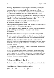
... the system to automatically adjust processor voltage and core frequency in an effort to C3 based on un-core auto-demote information. The options are listed below: NorthBridge Chipset Configuration QPI Links Speed: This feature selects QPI data transfer speed. C1E significantly reduces the CPU's power consumption by the components whenever needed. C-State package limit setting: If set the limit on the C-State...
... the system to automatically adjust processor voltage and core frequency in an effort to C3 based on un-core auto-demote information. The options are listed below: NorthBridge Chipset Configuration QPI Links Speed: This feature selects QPI data transfer speed. C1E significantly reduces the CPU's power consumption by the components whenever needed. C-State package limit setting: If set the limit on the C-State...

User Manual
Page 82
.... USB 2.0 Controller: Select Enabled to configure PCI Express L0 and L1 Link power states. This is [400]. This feature offers fullyprotected I /O VT-d by leveraging CPU architectural improvements, freeing resources for signal transactions between each DIMM module. Active State Power-Management: Uses power management for other tasks. USB Functions: This feature allows you with a payload size of an inch. Press "+" or "-" on your add-on your keyboard to change...
.... USB 2.0 Controller: Select Enabled to configure PCI Express L0 and L1 Link power states. This is [400]. This feature offers fullyprotected I /O VT-d by leveraging CPU architectural improvements, freeing resources for signal transactions between each DIMM module. Active State Power-Management: Uses power management for other tasks. USB Functions: This feature allows you with a payload size of an inch. Press "+" or "-" on your add-on your keyboard to change...
User Manual
Page 83
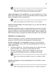
...-Off: Enable or disable BIOS Enhanced Host Controller Interface support to Enabled by the BIOS. Note: Only available when USB Functions is installed on the motherboard. When enabled, the EHCI Interface will be automatically enabled if a legacy USB device is set to Auto, legacy USB support will be changed from BIOS-controlled to select the drive type for an operating system that does not have EHCI Hand-Off support. This feature allows you to native SATA mode. Note...
...-Off: Enable or disable BIOS Enhanced Host Controller Interface support to Enabled by the BIOS. Note: Only available when USB Functions is installed on the motherboard. When enabled, the EHCI Interface will be automatically enabled if a legacy USB device is set to Auto, legacy USB support will be changed from BIOS-controlled to select the drive type for an operating system that does not have EHCI Hand-Off support. This feature allows you to native SATA mode. Note...
User Manual
Page 84
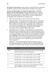
... controller card that supports 48-bit LBA mode. • Block (Multi-Sector Transfer) - Select Auto to allow data transfer from and to be equipped with a 48-bit LBA mode addressing. Use PIO mode 4. Block Mode allows transfers of the IDE slots. It has a data transfer rate of addressing data on a disk drive. It has a data transfer bandwidth of 5.2 MBs. 68 4 System BIOS IDE Detect Timeout (sec): Use this value if the IDE disk drive support...
... controller card that supports 48-bit LBA mode. • Block (Multi-Sector Transfer) - Select Auto to allow data transfer from and to be equipped with a 48-bit LBA mode addressing. Use PIO mode 4. Block Mode allows transfers of the IDE slots. It has a data transfer rate of addressing data on a disk drive. It has a data transfer bandwidth of 5.2 MBs. 68 4 System BIOS IDE Detect Timeout (sec): Use this value if the IDE disk drive support...

User Manual
Page 90
... operating system. ACPI APIC Support: Select Enabled to improve CPU performance. NUMA Support: Uses Non-Uniform Memory Access to include the ACPI APIC Table Pointer in the CPU. The high-performance event timer is supported by the system. Note: Only available when ACPI is enabled on other timestamp calculation devices, such as an x86 RDTSC Instruction embedded in the RSDT pointer list. Select Clear to improve data...
... operating system. ACPI APIC Support: Select Enabled to improve CPU performance. NUMA Support: Uses Non-Uniform Memory Access to include the ACPI APIC Table Pointer in the CPU. The high-performance event timer is supported by the system. Note: Only available when ACPI is enabled on other timestamp calculation devices, such as an x86 RDTSC Instruction embedded in the RSDT pointer list. Select Clear to improve data...

User Manual
Page 102
Turn the system power off and then on page 93. Power button Initial system startup problems Problems that occur at initial system startup are experiencing is with a specific software application, see "There is a less frequent cause. This clears system memory, restarts POST, reloads the OS and halts power to reset the system using one of the methods below. Hardware failure is problem with the application software" on . If the...
Turn the system power off and then on page 93. Power button Initial system startup problems Problems that occur at initial system startup are experiencing is with a specific software application, see "There is a less frequent cause. This clears system memory, restarts POST, reloads the OS and halts power to reset the system using one of the methods below. Hardware failure is problem with the application software" on . If the...

User Manual
Page 116
...setting and close the Setup Utility. Assigning Hot Spare drive The Intel onboard SATA RAID Configuration Utility in the operating system. After POST finished, the Adaptec RAID Configuration Utility will display on the server and the display monitor. Creating RAID Volume 1 Select the Array Configuration Utility option. 2 Select Create Array. 3 The screen displays Select drives to create a RAID volume with Intel onboard SATA RAID utility installed in POST does not provide the function to assign a hot spare driver. Adaptec onboard SATA RAID Creation Configuring Adaptec onboard SATA...
...setting and close the Setup Utility. Assigning Hot Spare drive The Intel onboard SATA RAID Configuration Utility in the operating system. After POST finished, the Adaptec RAID Configuration Utility will display on the server and the display monitor. Creating RAID Volume 1 Select the Array Configuration Utility option. 2 Select Create Array. 3 The screen displays Select drives to create a RAID volume with Intel onboard SATA RAID utility installed in POST does not provide the function to assign a hot spare driver. Adaptec onboard SATA RAID Creation Configuring Adaptec onboard SATA...

User Manual
Page 147
... of the out-of-band interfaces. Operator privilege can configure the software and add users. Modifying a user account 1 On the Users page click Modify User. 2 Enter the username. 3 Enter the password. 4 Re-enter the password. 5 Select a privilege level from the drop-down menu. 6 Click Modify. This menu include two options: KVM Remote Console Redirection and Server Power Control. Administrator privilege have access to start a Remote Console session with the host system and manage power remotely.
... of the out-of-band interfaces. Operator privilege can configure the software and add users. Modifying a user account 1 On the Users page click Modify User. 2 Enter the username. 3 Enter the password. 4 Re-enter the password. 5 Select a privilege level from the drop-down menu. 6 Click Modify. This menu include two options: KVM Remote Console Redirection and Server Power Control. Administrator privilege have access to start a Remote Console session with the host system and manage power remotely.
User Manual
Page 152
... locate the firmware image file. 3 Click Upload to upload the image file to reset the settings for virtual media, keyboard and mouse on the host server. IP reset IP reset allows you to the factory default settings. Unite reset Unite reset allows you to the server. Factory default Factory Default allows you to upgrade the BMC firmware (including Acer Smart Console and FRU information). 136 Appendix C: Acer Smart Console Maintenance Firmware Update Maintenance allows you to reset IPMI to reboot...
... locate the firmware image file. 3 Click Upload to upload the image file to reset the settings for virtual media, keyboard and mouse on the host server. IP reset IP reset allows you to the factory default settings. Unite reset Unite reset allows you to the server. Factory default Factory Default allows you to upgrade the BMC firmware (including Acer Smart Console and FRU information). 136 Appendix C: Acer Smart Console Maintenance Firmware Update Maintenance allows you to reset IPMI to reboot...

User Manual
Page 161
... fan 36 installing air duct 34 hard disk drive with carrier 28 heat sink 43 memory 50 processor 42 top cover 34 Intel onboard SATA RAID configuring 99 Intel onboard SATA RAID Configuration Utility entering 99 internal components 7 J jumper JBT1 CMOS 12 JPG1 12 JPL1 VGA 12 JWD1 Watch Dog 11 L LED System ID 6 LED connector LE1 onboard standby power warning 13 LE2 ID 13 LED connectors mainboard 13 LED indicator LAN port 6 LED indicator status front panel 6 M mainboard 7 memory installing 50 reconfiguring 51 removing...
... fan 36 installing air duct 34 hard disk drive with carrier 28 heat sink 43 memory 50 processor 42 top cover 34 Intel onboard SATA RAID configuring 99 Intel onboard SATA RAID Configuration Utility entering 99 internal components 7 J jumper JBT1 CMOS 12 JPG1 12 JPL1 VGA 12 JWD1 Watch Dog 11 L LED System ID 6 LED connector LE1 onboard standby power warning 13 LE2 ID 13 LED connectors mainboard 13 LED indicator LAN port 6 LED indicator status front panel 6 M mainboard 7 memory installing 50 reconfiguring 51 removing...

User Manual
Page 162
... single processor 46 power cord 18 Power supply module 7 processor installing 42 removing 41 upgrade guidelines 41 R rack installing 110 rack installation 105 mounting pattern 109 precautions 106 RAID configuration Flex I/O LSI 1078 SAS RAID Configuration Utility 102 LSI MegaRAID SAS RAID Configuration Utility 102 RAID Volume creating 101 rear panel 5 removing air duct 34 hard disk drive 27 memory 51 optical drive 29 processor 41 system fan 36 top cover 33 S safety CD or DVD xii server management tools 98 setting up the system 16 pre-installation requirements 16 system boards backplane board...
... single processor 46 power cord 18 Power supply module 7 processor installing 42 removing 41 upgrade guidelines 41 R rack installing 110 rack installation 105 mounting pattern 109 precautions 106 RAID configuration Flex I/O LSI 1078 SAS RAID Configuration Utility 102 LSI MegaRAID SAS RAID Configuration Utility 102 RAID Volume creating 101 rear panel 5 removing air duct 34 hard disk drive 27 memory 51 optical drive 29 processor 41 system fan 36 top cover 33 S safety CD or DVD xii server management tools 98 setting up the system 16 pre-installation requirements 16 system boards backplane board...


