User Manual
Page 1
... of Contents English Preface ...2 FCC Statement Warning ...2 Canadian DOC Notice ...2 Important Safety Instructions...3 Special Notes on LCD Monitors 3 Chapter 1 Installation ...4 Unpacking...4 Viewing Angle Adjustment ...4 Detaching LCD Monitor from Its Stand 4 Interface for Arm Applications ...5 Connecting the Display...5 Connecting the AC Power ...5 Power Management System...5 Chapter 2 Display Controls 6 General Instructions...6 Front Panel Control ...7 How to Adjust a Setting...8 Adjusting the Picture ...8 Chapter 3 Technical Information 10 Specifications...10 Standard...
... of Contents English Preface ...2 FCC Statement Warning ...2 Canadian DOC Notice ...2 Important Safety Instructions...3 Special Notes on LCD Monitors 3 Chapter 1 Installation ...4 Unpacking...4 Viewing Angle Adjustment ...4 Detaching LCD Monitor from Its Stand 4 Interface for Arm Applications ...5 Connecting the Display...5 Connecting the AC Power ...5 Power Management System...5 Chapter 2 Display Controls 6 General Instructions...6 Front Panel Control ...7 How to Adjust a Setting...8 Adjusting the Picture ...8 Chapter 3 Technical Information 10 Specifications...10 Standard...

User Manual
Page 2
...to assist users in a residential installation. Warning Use only shielded signal cables to connect I/O devices to provide reasonable protection against harmful interference in setting up and using the LCD Monitor. All rights are cautioned that changes or ...frequency energy, and if not installed and used in this manual may cause harmful interference to operate the equipment. No part of the Canadian Interference-Causing Equipment Regulations. FCC Statement Warning This equipment has been tested and found to comply with the instruction, may be determined by turning...
...to assist users in a residential installation. Warning Use only shielded signal cables to connect I/O devices to provide reasonable protection against harmful interference in setting up and using the LCD Monitor. All rights are cautioned that changes or ...frequency energy, and if not installed and used in this manual may cause harmful interference to operate the equipment. No part of the Canadian Interference-Causing Equipment Regulations. FCC Statement Warning This equipment has been tested and found to comply with the instruction, may be determined by turning...

User Manual
Page 3
... remain after switching the image, when the same image is damaged. 7. Storing the LCD Monitor outside this unit by changing the image or turning off the Power Switch for hours. FOR MORE INFORMATION, CONTACT THE ELECTRONIC INDUSTRIES ALLIANCE AT WWW.EIAE.ORG. Important Safety Instructions Please read the following symptoms are normal with LCD monitor and do not indicate a problem. To clean LCD Monitor screen; -- Exposing the monitor to...
... remain after switching the image, when the same image is damaged. 7. Storing the LCD Monitor outside this unit by changing the image or turning off the Power Switch for hours. FOR MORE INFORMATION, CONTACT THE ELECTRONIC INDUSTRIES ALLIANCE AT WWW.EIAE.ORG. Important Safety Instructions Please read the following symptoms are normal with LCD monitor and do not indicate a problem. To clean LCD Monitor screen; -- Exposing the monitor to...
User Manual
Page 4
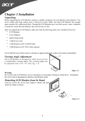
... viewing angle. You need a stable and clean surface near a wall power outlet. Viewing Angle Adjustment The LCD Monitor is needed to +15°.(See fig. 1-1) Figure 1-1 Warning Do not force the LCD Monitor over its maximum viewing angle settings as stated above. Attempting this will result in the box: * LCD Monitor * User's Manual * Quick Setup Guide * 1.8M Power Cord * 1.8M Monitor-to-PC D-SUB Cable * 1.8M Monitor-to release. Figure 1-2 4 Chapter 1 Installation Unpacking Before unpacking the LCD Monitor, prepare...
... viewing angle. You need a stable and clean surface near a wall power outlet. Viewing Angle Adjustment The LCD Monitor is needed to +15°.(See fig. 1-1) Figure 1-1 Warning Do not force the LCD Monitor over its maximum viewing angle settings as stated above. Attempting this will result in the box: * LCD Monitor * User's Manual * Quick Setup Guide * 1.8M Power Cord * 1.8M Monitor-to-PC D-SUB Cable * 1.8M Monitor-to release. Figure 1-2 4 Chapter 1 Installation Unpacking Before unpacking the LCD Monitor, prepare...

User Manual
Page 5
.... 4. Connect the power cord to Fig.1-2. signal. When the LCD Monitor is in Figure 1-3. Connect one end of the signal cable to the D-SUB or DVI (option) port on your computer. 2. Figure 1-3 Figure 1-4 Figure 1-5 Power Management System This LCD Monitor complies with the VESA DPMS (version 1.0) Power Management guidelines. Connecting the AC Power 1. The VESA DPMS provides four power saving modes through detecting a horizontal or vertical sync. Make sure connections are secure. These specifications meet the VESA Flat Panel Monitor Physical Mounting Interface...
.... 4. Connect the power cord to Fig.1-2. signal. When the LCD Monitor is in Figure 1-3. Connect one end of the signal cable to the D-SUB or DVI (option) port on your computer. 2. Figure 1-3 Figure 1-4 Figure 1-5 Power Management System This LCD Monitor complies with the VESA DPMS (version 1.0) Power Management guidelines. Connecting the AC Power 1. The VESA DPMS provides four power saving modes through detecting a horizontal or vertical sync. Make sure connections are secure. These specifications meet the VESA Flat Panel Monitor Physical Mounting Interface...
User Manual
Page 6
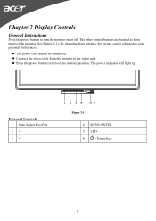
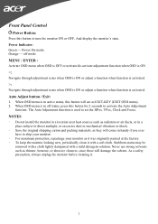
External Controls 1 Auto Adjust Key/Exit 2 < 3 > Figure 2-1 4 MENU/ENTER 5 LED 6 / Power Key 6 By changing these settings, the picture can be connected. Chapter 2 Display Controls General Instructions Press the power button to turn on or off. The other control buttons are located at front panel of the monitor (See Figure 2-1). z The power cord should be adjusted to your personal preferences. z Connect the video cable from the monitor to turn the monitor on the monitor position. The power indicator will light up. z Press the power button to the video card.
External Controls 1 Auto Adjust Key/Exit 2 < 3 > Figure 2-1 4 MENU/ENTER 5 LED 6 / Power Key 6 By changing these settings, the picture can be connected. Chapter 2 Display Controls General Instructions Press the power button to turn on or off. The other control buttons are located at front panel of the monitor (See Figure 2-1). z The power cord should be adjusted to your personal preferences. z Connect the video cable from the monitor to turn the monitor on the monitor position. The power indicator will light up. z Press the power button to the video card.
User Manual
Page 7
... have to ship your monitor. ‧ For maximum protection, repackage your monitor as it was originally packed at the factory. ‧ To keep the monitor looking new, periodically clean it . 7 Stubborn stains may be removed with a cloth lightly dampened with a soft cloth. The Auto Adjustment function is in active status, this button to turn the monitor ON or OFF, And display the monitor's state. Power On mode.
... have to ship your monitor. ‧ For maximum protection, repackage your monitor as it was originally packed at the factory. ‧ To keep the monitor looking new, periodically clean it . 7 Stubborn stains may be removed with a cloth lightly dampened with a soft cloth. The Auto Adjustment function is in active status, this button to turn the monitor ON or OFF, And display the monitor's state. Power On mode.

User Manual
Page 8
... screen image. Position N/A Warm N/A Cool User / Red Adjust picture Clock Set the color temperature to change the settings of the current function. 5. Press < or > to warm white. Position Adjust picture Focus V. If you want to Adjust a Setting 1. User / Green Adjusts Red/Green/Blue intensity. How to adjust any other function, repeat steps 2-4. (option) Adjusting the Picture The descriptions for function control LEDS Main Menu Icon Sub Menu Icon Sub Menu Item Contrast Brightness Description Adjusts the contrast between the foreground and background of the screen image...
... screen image. Position N/A Warm N/A Cool User / Red Adjust picture Clock Set the color temperature to change the settings of the current function. 5. Press < or > to warm white. Position Adjust picture Focus V. If you want to Adjust a Setting 1. User / Green Adjusts Red/Green/Blue intensity. How to adjust any other function, repeat steps 2-4. (option) Adjusting the Picture The descriptions for function control LEDS Main Menu Icon Sub Menu Icon Sub Menu Item Contrast Brightness Description Adjusts the contrast between the foreground and background of the screen image...
User Manual
Page 9
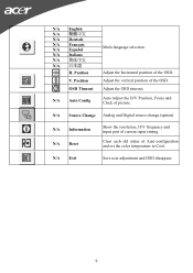
Clear each old status of the OSD. Adjust the horizontal position of Auto-configuration and set the color temperature to Cool. N/A Auto Config Auto Adjust the H/V Position, Focus and Clock of the OSD. V. N/A Exit Save user adjustment and OSD disappear. 9 Position Adjust the vertical position of picture. N/A Source Change Analog and Digital source change.(option) N/A Information N/A Reset Show the resolution, H/V frequency and input port of current input timing. Position Multi-language selection. N/A English N/A N/A Deutsch N/A Français N/A Español N/A ...
Clear each old status of the OSD. Adjust the horizontal position of Auto-configuration and set the color temperature to Cool. N/A Auto Config Auto Adjust the H/V Position, Focus and Clock of the OSD. V. N/A Exit Save user adjustment and OSD disappear. 9 Position Adjust the vertical position of picture. N/A Source Change Analog and Digital source change.(option) N/A Information N/A Reset Show the resolution, H/V frequency and input port of current input timing. Position Multi-language selection. N/A English N/A N/A Deutsch N/A Français N/A Español N/A ...
User Manual
Page 10
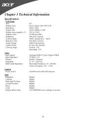
... Voltage Lamp Current Viewing Angle Video Input Signal Input Impedance Polarity Amplitude Multi-mode Supported Control Power switch OSD Brightness Contrast Horizontal Position Vertical Position Phase Clock Display Mode Setup 24" Active matrix color TFT LCD 1920 x 1200 1920 x (RGB) x 1200 518.4 x 324.0 16.2M (ture 8bit) 500 cd/m2 (typical) 1000:1 (typical & IL = 6mA) 6ms (Gray to Gray) 1800 Vrms (typical) 6.0 mA rms. (typical) Vertical: 178° Horizontal: 178° Analogue RGB 0.7Vp-p/ Digital TMDS 75 Ohm...
... Voltage Lamp Current Viewing Angle Video Input Signal Input Impedance Polarity Amplitude Multi-mode Supported Control Power switch OSD Brightness Contrast Horizontal Position Vertical Position Phase Clock Display Mode Setup 24" Active matrix color TFT LCD 1920 x 1200 1920 x (RGB) x 1200 518.4 x 324.0 16.2M (ture 8bit) 500 cd/m2 (typical) 1000:1 (typical & IL = 6mA) 6ms (Gray to Gray) 1800 Vrms (typical) 6.0 mA rms. (typical) Vertical: 178° Horizontal: 178° Analogue RGB 0.7Vp-p/ Digital TMDS 75 Ohm...
User Manual
Page 11
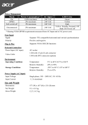
... 240 VAC 240 VAC 240 VAC LED Color Green Yellow Dark Yellow: Standby, Suspend, Off Dark: DC Power off * Meeting VESA DPMS requirements measured from AC Input end of AC power cord. Sync Input Signal Polarity Plug & Play Separate TTL compatible horizontal and vertical synchronization Positive and negative Supports VESA DDC2B functions External Connection Power Input (AC input) Video Cable AC socket 1.8M with 15-pin D-sub connector 1.8M with DVI connector (option) Environment Operating Condition: Storage...
... 240 VAC 240 VAC 240 VAC LED Color Green Yellow Dark Yellow: Standby, Suspend, Off Dark: DC Power off * Meeting VESA DPMS requirements measured from AC Input end of AC power cord. Sync Input Signal Polarity Plug & Play Separate TTL compatible horizontal and vertical synchronization Positive and negative Supports VESA DDC2B functions External Connection Power Input (AC input) Video Cable AC socket 1.8M with 15-pin D-sub connector 1.8M with DVI connector (option) Environment Operating Condition: Storage...
User Manual
Page 12
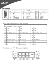
... power *) 7 DDC-Serial Data 15 Ground (+5V) 8 NC 16 Hot plug detect Pin assignment for DVI - Sync. 14 V. D Connector (option): 17 TX018 TX0+ 19 Shield (TX0 / TX5) 20 NC 21 NC 22 Shield (TXC) 23 TXC+ 24 TXC- 12 Pin Assignment 6 PIN 1 11 1 2 5 15 3 4 10 5 Description Red Green Blue Digital GND Digital GND Signal PIN Description 6 Red Rtn 7 Green Rtn 8 Blue Rtn 9 +5V 10 Hot Plug...
... power *) 7 DDC-Serial Data 15 Ground (+5V) 8 NC 16 Hot plug detect Pin assignment for DVI - Sync. 14 V. D Connector (option): 17 TX018 TX0+ 19 Shield (TX0 / TX5) 20 NC 21 NC 22 Shield (TXC) 23 TXC+ 24 TXC- 12 Pin Assignment 6 PIN 1 11 1 2 5 15 3 4 10 5 Description Red Green Blue Digital GND Digital GND Signal PIN Description 6 Red Rtn 7 Green Rtn 8 Blue Rtn 9 +5V 10 Hot Plug...
User Manual
Page 13
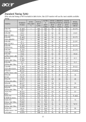
TIMING FH(KHZ) FV(HZ) SYNC POLARIT Y TOTAL (DOT /LINE) ACTIV E (DOT /LINE) SYNC WIDTH (DOT /LINE) FRONT PORCH (DOT /LINE) BACK PORCH (DOT /LINE) PIXEL FOREQ. (MHZ) 640x350 31.469 + 800 640 96 16 48 25.175 VGA-350 70.087 - 449 350 2 37 60 640x400 24.83 - 848 640 64 64 80...75 VESA-768-75Hz 75.029 + 800 768 3 1 28 1024x768 60.24 - 1328 1024 96 32 176 80 APPLE MAC-768 75.02 - 803 768 3 3 29 1152x864 54.054 + 1480 1152 96 40 192 80 13 Standard Timing Table If the selected timing is NOT included in table below, this LCD monitor will use ...
TIMING FH(KHZ) FV(HZ) SYNC POLARIT Y TOTAL (DOT /LINE) ACTIV E (DOT /LINE) SYNC WIDTH (DOT /LINE) FRONT PORCH (DOT /LINE) BACK PORCH (DOT /LINE) PIXEL FOREQ. (MHZ) 640x350 31.469 + 800 640 96 16 48 25.175 VGA-350 70.087 - 449 350 2 37 60 640x400 24.83 - 848 640 64 64 80...75 VESA-768-75Hz 75.029 + 800 768 3 1 28 1024x768 60.24 - 1328 1024 96 32 176 80 APPLE MAC-768 75.02 - 803 768 3 3 29 1152x864 54.054 + 1480 1152 96 40 192 80 13 Standard Timing Table If the selected timing is NOT included in table below, this LCD monitor will use ...
User Manual
Page 14
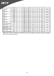
... + 1800 1280 112 96 312 135.00 + 1000 960 3 1 36 1280x1024 64 + 1688 1280 112 48 248 108 VESA-1024-60Hz 60 + 1066 1024 3 1 38 1280x1024 80 + 1688 1280 144 16 248 135 VESA-1024-75Hz 75 + 1066 1024 3 1 38 1600x1200 75 + 2160 1600 192 64 304 162 VGSA-1200-60Hz 60... + 1250 1200 50 1 46 1920x1200 74.6 + 2592 1920 200 136 336 193 VGSA-1200-60Hz 60 + 1245 1200 6 3 36 Note: Mode 640x350, 640x400 and 720x400 will locate on middle position but cannot be expanded to full screen on vertical direction. 14
... + 1800 1280 112 96 312 135.00 + 1000 960 3 1 36 1280x1024 64 + 1688 1280 112 48 248 108 VESA-1024-60Hz 60 + 1066 1024 3 1 38 1280x1024 80 + 1688 1280 144 16 248 135 VESA-1024-75Hz 75 + 1066 1024 3 1 38 1600x1200 75 + 2160 1600 192 64 304 162 VGSA-1200-60Hz 60... + 1250 1200 50 1 46 1920x1200 74.6 + 2592 1920 200 136 336 193 VGSA-1200-60Hz 60 + 1245 1200 6 3 36 Note: Mode 640x350, 640x400 and 720x400 will locate on middle position but cannot be expanded to full screen on vertical direction. 14

User Manual
Page 15
...'t work, connect your LCD Monitor. Also, if the signal cable is not connected to the output timing differences among various VGA cards in the market, users may be out of the "Clock" function in OSD menu again and adjust the monitor screen to another external CRT. Due to LCD monitor at all connections are , take advantage of the LCD's synchronous range. Attention This LCD Monitor Supports Multiple VGA Modes. In Windows XP open the specific application where the problems appear. 2. PROBLEM...
...'t work, connect your LCD Monitor. Also, if the signal cable is not connected to the output timing differences among various VGA cards in the market, users may be out of the "Clock" function in OSD menu again and adjust the monitor screen to another external CRT. Due to LCD monitor at all connections are , take advantage of the LCD's synchronous range. Attention This LCD Monitor Supports Multiple VGA Modes. In Windows XP open the specific application where the problems appear. 2. PROBLEM...


