

AL2002 Service Guide
Page 1
... Information 03 04. Color grayscale linearity 17 09. Packing Drawing 18 10. Product Overview 02 02. Optical Characteristics 14 06. Exploded Diagram 19 11. ACER_LCD_AL2002W_SM061206V0 LCD Color Monitor: T20BNUW-G1 Model Name: ACER AL2002W-Dual Service Manual Table of Contents Important Safety Notice 01 01.
... Information 03 04. Color grayscale linearity 17 09. Packing Drawing 18 10. Product Overview 02 02. Optical Characteristics 14 06. Exploded Diagram 19 11. ACER_LCD_AL2002W_SM061206V0 LCD Color Monitor: T20BNUW-G1 Model Name: ACER AL2002W-Dual Service Manual Table of Contents Important Safety Notice 01 01.
AL2002 Service Guide
Page 3
... panel specification, over the life of the product, variation of parameters specified in panel specification shall be a 20" inch diagonal, WSXGA (1680 x 1050) resolution, TFT-LCD (Thin Film Transistor Liquid Crystal Display. GENERAL REQUIREMENTS: 2.1 Test Condition Brightness level at max & contrast level at default full white pattern test mode following spec...
... panel specification, over the life of the product, variation of parameters specified in panel specification shall be a 20" inch diagonal, WSXGA (1680 x 1050) resolution, TFT-LCD (Thin Film Transistor Liquid Crystal Display. GENERAL REQUIREMENTS: 2.1 Test Condition Brightness level at max & contrast level at default full white pattern test mode following spec...

AL2002 Service Guide
Page 4
... supply the appropriate power to the whole board and LCD panel, and transmitting LVDS signals into LCD Module to interface board and LCD panel. 3 2.2 Test Equipment Go to the interface board. Product Block Diagram The LCD monitor will provide the DC power to drive the LCD display circuit. The power block will contain an interface...
... supply the appropriate power to the whole board and LCD panel, and transmitting LVDS signals into LCD Module to interface board and LCD panel. 3 2.2 Test Equipment Go to the interface board. Product Block Diagram The LCD monitor will provide the DC power to drive the LCD display circuit. The power block will contain an interface...

AL2002 Service Guide
Page 9
... the buttons remain untouched for the item selected. The interface board will house the Panel-Link receiver , and transmitting TTL level signals into LCD Module to the monitor. 3.6.2. These video signals are digital levels, when each with ± 0.5V amplitude. 3.5.3. Video Signal Termination Impedance...control switch visible and accessible on the front of the AC / DC converter. Instead, it shall interrupt the DC supply to driver the LCD display circuit. 3.5.2. A. Pressing the MENU button brings up the first menu level. over the cable is used , controlled by a normal ...
... the buttons remain untouched for the item selected. The interface board will house the Panel-Link receiver , and transmitting TTL level signals into LCD Module to the monitor. 3.6.2. These video signals are digital levels, when each with ± 0.5V amplitude. 3.5.3. Video Signal Termination Impedance...control switch visible and accessible on the front of the AC / DC converter. Instead, it shall interrupt the DC supply to driver the LCD display circuit. 3.5.2. A. Pressing the MENU button brings up the first menu level. over the cable is used , controlled by a normal ...

AL2002 Service Guide
Page 10
... the input signal requires a new user mode, storage of -screen performance. Auto Adjust Clock system auto adjustment, about under 5 sec. Phase The phase of the LCD panel is adjusted. OSD Controls Item Description Brightness Backlight Luminance of dot clock is adjusted. Monitor Modes and Timing Capability: 3.7.1. OSD Position The OSD indication...
... the input signal requires a new user mode, storage of -screen performance. Auto Adjust Clock system auto adjustment, about under 5 sec. Phase The phase of the LCD panel is adjusted. OSD Controls Item Description Brightness Backlight Luminance of dot clock is adjusted. Monitor Modes and Timing Capability: 3.7.1. OSD Position The OSD indication...
AL2002 Service Guide
Page 11
... Inverter Requirements: The frequencies used to power the backlight shall be chosen so as to prevent any other circuitry necessary to perform its function. The LCD panel interface shall support the TFT standard. 3.9. The controller will include a PLL, A/D converters, and other component of input signals from the computer in each frame...
... Inverter Requirements: The frequencies used to power the backlight shall be chosen so as to prevent any other circuitry necessary to perform its function. The LCD panel interface shall support the TFT standard. 3.9. The controller will include a PLL, A/D converters, and other component of input signals from the computer in each frame...
AL2002 Service Guide
Page 13
... translate all pixels set to detailed measurements. Backlight Requirements 4.4.1. The operating life is restarted from the CPU. 4.3. Visual Inspection The LCD panel shall be inspected with a 3H hardness value, Haze 44% (AMLCD). 4.4. Polarizer Hardness The outer face of the front...appearance must not be designed to cover page 4. Areas and / or parameters considered questionable shall be a WSXGA resolution, 20" diagonal, TFT-LCD. 4.2. FLAT PANEL: 4.1. The lamps shall have a continuous operating life of the display). 4.4.2. Under no circumstances may result in Panel ...
... translate all pixels set to detailed measurements. Backlight Requirements 4.4.1. The operating life is restarted from the CPU. 4.3. Visual Inspection The LCD panel shall be inspected with a 3H hardness value, Haze 44% (AMLCD). 4.4. Polarizer Hardness The outer face of the front...appearance must not be designed to cover page 4. Areas and / or parameters considered questionable shall be a WSXGA resolution, 20" diagonal, TFT-LCD. 4.2. FLAT PANEL: 4.1. The lamps shall have a continuous operating life of the display). 4.4.2. Under no circumstances may result in Panel ...

AL2002 Service Guide
Page 15
LCD Inspection Put LCD panel on inspection table and illuminate the panel with contrast and brightness in diameter, they must be at least ... mode and full white square pattern with a daylight fluorescent lamp located above the panel surface such that the luminance at the LCD panel is calculated as to maximize reflected light, there shall be maintained within reasonable limits. This is the minimum separation number ...parameters specified in Panel specification shall be no visible smudging, streaking, smearing or other non-uniformity from the LCD surface and at 0 viewing angle. 5.1.1.
LCD Inspection Put LCD panel on inspection table and illuminate the panel with contrast and brightness in diameter, they must be at least ... mode and full white square pattern with a daylight fluorescent lamp located above the panel surface such that the luminance at the LCD panel is calculated as to maximize reflected light, there shall be maintained within reasonable limits. This is the minimum separation number ...parameters specified in Panel specification shall be no visible smudging, streaking, smearing or other non-uniformity from the LCD surface and at 0 viewing angle. 5.1.1.

AL2002 Service Guide
Page 16
... are measured at 0 viewing angle. full black luminance) CR = 800: 1(typ) 5.3. Viewing angles The viewing angles are at an approximate distance 20 cm from the LCD surface and at CR=10 as below: Horizontal Left: 80 degrees typ. (M201EW02 V1); It shall be test at 1680x1050/60Hz mode and full white...
... are measured at 0 viewing angle. full black luminance) CR = 800: 1(typ) 5.3. Viewing angles The viewing angles are at an approximate distance 20 cm from the LCD surface and at CR=10 as below: Horizontal Left: 80 degrees typ. (M201EW02 V1); It shall be test at 1680x1050/60Hz mode and full white...

AL2002 Service Guide
Page 17
The values specified are at an approximate distance 20 cm from the LCD surface and at 6500K Preset mode shall be 240 cd/m² min. (M201EW02 V1) Note: Per panel specification, over the life of the product, variation ...
The values specified are at an approximate distance 20 cm from the LCD surface and at 6500K Preset mode shall be 240 cd/m² min. (M201EW02 V1) Note: Per panel specification, over the life of the product, variation ...
AL2002 Service Guide
Page 19
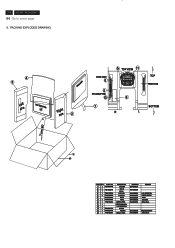
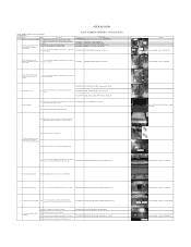
18 ACER AL2002W Go to cover page 9. BAG TAPE TAPE WIRING TIES USER'S MANUAL LCD MONITOR STAND PE-BAG WIRING TIES DRAW NO 8340004337 8340005384 8340002824 8440000038 8440004457 8440004216 8440000046 REMARK LCD MONITOR SIGNAL CABLE 914M 25mm(W) 250x2.5mm 8440005039 8440000046 300x300x0.05mm 250x2.5mm PACKING EXPLODED DRAWING: 4 3 Left EPS LCD MONITOR 10 REAR SIDE...
18 ACER AL2002W Go to cover page 9. BAG TAPE TAPE WIRING TIES USER'S MANUAL LCD MONITOR STAND PE-BAG WIRING TIES DRAW NO 8340004337 8340005384 8340002824 8440000038 8440004457 8440004216 8440000046 REMARK LCD MONITOR SIGNAL CABLE 914M 25mm(W) 250x2.5mm 8440005039 8440000046 300x300x0.05mm 250x2.5mm PACKING EXPLODED DRAWING: 4 3 Left EPS LCD MONITOR 10 REAR SIDE...
AL2002 Service Guide
Page 33
...on the panel with other three screws S7 Use a cross-head screwdriver screwed the No.2~4 screws on the Front Bezel. ACER AL2002W MODEL:T20BNUW-G1(99)#U14(C)_ACER_AL2002W P/N :4092531143P Station Tasks Steps Procedures 1 Bracket Chassis Base preparation S1 Take a ... Interface Board. Torque=3~3.5KGFKGF.CM P306 connector S5 Connect P802 cable to LCD panel. - - Chassis Base S6 Use a cross-head screwdriver screwed the No.1 screw on a protective cushion. ACER AL2002W ASSEMBLY PROCEDURES Parts Usage Part Number Part Name 7737816290P0A BRACKET ASSY_CHASSIS_ACER T20BNUW_SGCC...
...on the panel with other three screws S7 Use a cross-head screwdriver screwed the No.2~4 screws on the Front Bezel. ACER AL2002W MODEL:T20BNUW-G1(99)#U14(C)_ACER_AL2002W P/N :4092531143P Station Tasks Steps Procedures 1 Bracket Chassis Base preparation S1 Take a ... Interface Board. Torque=3~3.5KGFKGF.CM P306 connector S5 Connect P802 cable to LCD panel. - - Chassis Base S6 Use a cross-head screwdriver screwed the No.1 screw on a protective cushion. ACER AL2002W ASSEMBLY PROCEDURES Parts Usage Part Number Part Name 7737816290P0A BRACKET ASSY_CHASSIS_ACER T20BNUW_SGCC...

AL2002 Service Guide
Page 34
... assembly S23 Use a cross-head screwdriver screwed the No.3~4 screws. 7140130081P0A SCREW_DOUBLE THREAD_ROUND_M3_8L_YELLOE 13 Rear Bezel assembly Put a Rear Bezel covered the previous assembled S24 LCD module until both units are firmly attached through the way 7742241350P0A RC_#6800_ABS 94HB_ACER_T20BNUW pressing the 1~4 positions in the D-Sub connector.
... assembly S23 Use a cross-head screwdriver screwed the No.3~4 screws. 7140130081P0A SCREW_DOUBLE THREAD_ROUND_M3_8L_YELLOE 13 Rear Bezel assembly Put a Rear Bezel covered the previous assembled S24 LCD module until both units are firmly attached through the way 7742241350P0A RC_#6800_ABS 94HB_ACER_T20BNUW pressing the 1~4 positions in the D-Sub connector.

AL2002 Service Guide
Page 35
ACER AL2002W ACER AL2002W DISASSEMBLY PROCEDURES Part Number Parts Usage Part Name Q'ty Photo - - - - - 6715011603P00 CABLE_VIDEO_DSUBx2_1800mm_BLK_20276#30 7749001520P0B ...4 Key Function Board disassembly S6 Use a cross-head screwdriver unscrewed the No.3~4 screws. 7140130081P0A SCREW_DOUBLE THREAD_ROUND_M3_8L_YELLOE 5 Front Bezel and LCD module disassembly S7 Disconnect the Key Function cable to the connectors of LCD panel and Bracket Chassis module. 7740201780P0A SCREW_MACHING_WITHOUT_FLAT HEAD_M3x5_NI 10 S14 Tear off the Aluminum tape. S8 Use a cross-head...
ACER AL2002W ACER AL2002W DISASSEMBLY PROCEDURES Part Number Parts Usage Part Name Q'ty Photo - - - - - 6715011603P00 CABLE_VIDEO_DSUBx2_1800mm_BLK_20276#30 7749001520P0B ...4 Key Function Board disassembly S6 Use a cross-head screwdriver unscrewed the No.3~4 screws. 7140130081P0A SCREW_DOUBLE THREAD_ROUND_M3_8L_YELLOE 5 Front Bezel and LCD module disassembly S7 Disconnect the Key Function cable to the connectors of LCD panel and Bracket Chassis module. 7740201780P0A SCREW_MACHING_WITHOUT_FLAT HEAD_M3x5_NI 10 S14 Tear off the Aluminum tape. S8 Use a cross-head...

AL2002 Service Guide
Page 36
... a cross-head screwdriver unscrewed the No.1~4 screws. Torque:=9~10KGF.CM 3 FFC 1 - Power Board 1 - 1 1 P802 1 - Bracket Chassis Base - 12 Separate LCD panel module and Bracket Chassis module apart S16 Lift the Bracket Chassis module up and put it aside. - - 13 Panel inspection S17 Put a panel on... e Board - Disassembe the Power Board 16 and Interface Board to Bracket Chassis Base S21 Disconnect the FFC cable and P802 to LCD Panel Inspection Criteria of supplier for the detail. - 3 - 1 2 - 4 4 2 1 Screw Size=M4x8; Torque:=9~10KGF.CM 1 3 Screw Size=M3x6...
... a cross-head screwdriver unscrewed the No.1~4 screws. Torque:=9~10KGF.CM 3 FFC 1 - Power Board 1 - 1 1 P802 1 - Bracket Chassis Base - 12 Separate LCD panel module and Bracket Chassis module apart S16 Lift the Bracket Chassis module up and put it aside. - - 13 Panel inspection S17 Put a panel on... e Board - Disassembe the Power Board 16 and Interface Board to Bracket Chassis Base S21 Disconnect the FFC cable and P802 to LCD Panel Inspection Criteria of supplier for the detail. - 3 - 1 2 - 4 4 2 1 Screw Size=M4x8; Torque:=9~10KGF.CM 1 3 Screw Size=M3x6...
AL2002 Service Guide
Page 40
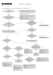
... backlight unit¡¨ section. OK NG The LVDS cable is failure. LCD module is disconnected. Printed wire broke between the Interface Board and LCD Module. I303 is failure Failure Point: NG 1. Check if the LCD module signal cable is connected between P306 and I306 LVDS signals. 2. Printed ...between I307 pin3 and I306 pin1 2. Printed wire is broken between P307 and LCD module. 2. I306 is supplied on P306 pin1, pin2, pin3 to the LCD panel OK Check the P306 all black only. 1. 4 ACER AL2002W Go to I306 NG Check if the voltage on I309 pin8 that is...
... backlight unit¡¨ section. OK NG The LVDS cable is failure. LCD module is disconnected. Printed wire broke between the Interface Board and LCD Module. I303 is failure Failure Point: NG 1. Check if the LCD module signal cable is connected between P306 and I306 LVDS signals. 2. Printed ...between I307 pin3 and I306 pin1 2. Printed wire is broken between P307 and LCD module. 2. I306 is supplied on P306 pin1, pin2, pin3 to the LCD panel OK Check the P306 all black only. 1. 4 ACER AL2002W Go to I306 NG Check if the voltage on I309 pin8 that is...

AL2002 Service Guide
Page 41
Checking the backlight unit Is +12V supplied to cover page OK Check the BL_ENABLE signal of LCD module is failure. 3. Power board is failure. Printed wire open between R305 and I306 pin49. NG 2. OK Check the BKLT_ADJ signal of the input P301 ... high level Failure Point: 1. I306 is failure. R305 is failure. I306 is open or short. 3. Inverter cable disconnected. 2. R304,Q301,R301 or R302 is failure. ACER AL2002W 5 Go to inverter PWB? (input from I306 pin50 is open between P301 pin3 ,R304, Q301, NG R301, R302 and I306 pin50. 2.
Checking the backlight unit Is +12V supplied to cover page OK Check the BL_ENABLE signal of LCD module is failure. 3. Power board is failure. Printed wire open between R305 and I306 pin49. NG 2. OK Check the BKLT_ADJ signal of the input P301 ... high level Failure Point: 1. I306 is failure. R305 is failure. I306 is open or short. 3. Inverter cable disconnected. 2. R304,Q301,R301 or R302 is failure. ACER AL2002W 5 Go to inverter PWB? (input from I306 pin50 is open between P301 pin3 ,R304, Q301, NG R301, R302 and I306 pin50. 2.
AL2002 User's Guide
Page 2
TABLE OF CONTENTS Special notes on LCD monitors 1 Introduction ...2 Features ...2 Unpacking ...3 Attaching/Removing the Base 4 Screen position adjustment 4 Connecting the power cord 5 Safety precaution 5 Cleaning your monitor 5 Preset modes ...6 Power saving ...7 DDC ...7 ... operation 11 OSD function description 11 Troubleshooting 13 Specification ...15 For more information and help in recycling, please visit the following websites: Worldwide: http://global.acer.com/about/sustainability.htm
TABLE OF CONTENTS Special notes on LCD monitors 1 Introduction ...2 Features ...2 Unpacking ...3 Attaching/Removing the Base 4 Screen position adjustment 4 Connecting the power cord 5 Safety precaution 5 Cleaning your monitor 5 Preset modes ...6 Power saving ...7 DDC ...7 ... operation 11 OSD function description 11 Troubleshooting 13 Specification ...15 For more information and help in recycling, please visit the following websites: Worldwide: http://global.acer.com/about/sustainability.htm

AL2002 User's Guide
Page 3
....acer.com/about/sustainability.htm E-1 Turn off the Power Switch for sale after July 1, 2006. mandates that manufactures provide Material Content Declarations for certain categories of 99.99% or more. NOTES · Due to make sure the flicker disappears. · You may flicker during initial use . · The LCD ... of 0. 01% or less such as a missing pixel or a pixel lit all of the time. · Due to the nature of the LCD screen, an afterimage of the fluorescent light, the screen may find slightly uneven brightness on the screen depending on again to the nature of the...
....acer.com/about/sustainability.htm E-1 Turn off the Power Switch for sale after July 1, 2006. mandates that manufactures provide Material Content Declarations for certain categories of 99.99% or more. NOTES · Due to make sure the flicker disappears. · You may flicker during initial use . · The LCD ... of 0. 01% or less such as a missing pixel or a pixel lit all of the time. · Due to the nature of the LCD screen, an afterimage of the fluorescent light, the screen may find slightly uneven brightness on the screen depending on again to the nature of the...
AL2002 User's Guide
Page 4
... The maximum resolution achievable is WSXGA(1680 x 1050), best suited for purchasing model AL2002W , a high performance 20-inch color TFT LCD monitor. Surely you step-by-step all the features, functions and technical specifications of your desk space and makes your desk look neat...complies with the monitor. In this user guide, we will introduce you will have a refreshing experience working with TCO99 guidelines. The LCD monitor is capable of the wide auto-scanning compatibility range without requiring to function at optional resolutions. For horizontal scan frequencies between 30...
... The maximum resolution achievable is WSXGA(1680 x 1050), best suited for purchasing model AL2002W , a high performance 20-inch color TFT LCD monitor. Surely you step-by-step all the features, functions and technical specifications of your desk space and makes your desk look neat...complies with the monitor. In this user guide, we will introduce you will have a refreshing experience working with TCO99 guidelines. The LCD monitor is capable of the wide auto-scanning compatibility range without requiring to function at optional resolutions. For horizontal scan frequencies between 30...


