AL1716e Service Guide
Page 21
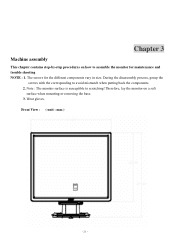
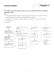
Chapter 3 Machine assembly This chapter contains step-by-step procedures on a soft surface when mounting or removing the base. 3. Wear gloves. Therefore, lay the monitor on how to scratching! Front View : ( unit : mm ) - 21 - Note : The monitor surface is susceptible to assemble the monitor for the different components vary in size. During the disassembly process, group the screws with the corresponding to avoid mismatch when putting back the components. 2. The screws for maintenance and trouble shooting NOTE : 1.
Chapter 3 Machine assembly This chapter contains step-by-step procedures on a soft surface when mounting or removing the base. 3. Wear gloves. Therefore, lay the monitor on how to scratching! Front View : ( unit : mm ) - 21 - Note : The monitor surface is susceptible to assemble the monitor for the different components vary in size. During the disassembly process, group the screws with the corresponding to avoid mismatch when putting back the components. 2. The screws for maintenance and trouble shooting NOTE : 1.
AL1716v Service Guide
Page 6
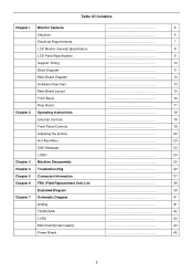
... 2 Operating Instructions 18 External Controls 18 Front Panel Controls 19 Adjusting the picture 20 Hot-Key Menu 23 OSD Message 23 LOGO 24 Chapter 3 Machine Disassembly 25 Chapter 4 Troubleshooting 32 Chapter 5 Connector Information 37 Chapter 6 FRU (Field Replacement Unit) List 38 Exploded Diagram 39 Chapter 7 Schematic Diagram 41 Analog 41 TSUM16AK...
... 2 Operating Instructions 18 External Controls 18 Front Panel Controls 19 Adjusting the picture 20 Hot-Key Menu 23 OSD Message 23 LOGO 24 Chapter 3 Machine Disassembly 25 Chapter 4 Troubleshooting 32 Chapter 5 Connector Information 37 Chapter 6 FRU (Field Replacement Unit) List 38 Exploded Diagram 39 Chapter 7 Schematic Diagram 41 Analog 41 TSUM16AK...

AL1716v Service Guide
Page 26
Disassembly Procedure Disassemble the base 1. Remove four screws to assemble the monitor for maintenance. Remove hinge cover. (Fig 1) 2. Chapter 3 Machine Disassembly This chapter contains step-by-step procedures on how to release stand base. (Fig 2) Fig 1 Fig 2 25
Disassembly Procedure Disassemble the base 1. Remove four screws to assemble the monitor for maintenance. Remove hinge cover. (Fig 1) 2. Chapter 3 Machine Disassembly This chapter contains step-by-step procedures on how to release stand base. (Fig 2) Fig 1 Fig 2 25

AL1716v Service Guide
Page 27
Disassemble the front cover and rear bezel 1. Remove five screws to release back cover and front bezel. (Fig 3) 2. Remove connector wire with keyboard and main board. (Fig 4) Fig 3 Fig 4 26
Disassemble the front cover and rear bezel 1. Remove five screws to release back cover and front bezel. (Fig 3) 2. Remove connector wire with keyboard and main board. (Fig 4) Fig 3 Fig 4 26

AL1716v Service Guide
Page 28
Fig 5 27 Disassemble the shield Remove two screws to release the shield. (Fig 5) (Remove the shield as arrow direction).
Fig 5 27 Disassemble the shield Remove two screws to release the shield. (Fig 5) (Remove the shield as arrow direction).

AL1716v Service Guide
Page 29
Disassemble the main board 1. Remove connector wire with main board and panel. (Fig 7) Fig 6 Fig 7 28 Remove three screws to release main board. (Fig 6) 2.
Disassemble the main board 1. Remove connector wire with main board and panel. (Fig 7) Fig 6 Fig 7 28 Remove three screws to release main board. (Fig 6) 2.

AL1716v Service Guide
Page 31
Remove four screws to release power board. (Fig 10) 2. Disassemble the power board 1. Remove connector wire with power board and panel. (Fig 11) Fig 10 Fig 11 30
Remove four screws to release power board. (Fig 10) 2. Disassemble the power board 1. Remove connector wire with power board and panel. (Fig 11) Fig 10 Fig 11 30

AL1716v Service Guide
Page 32
Disassemble the panel Remove four screws to release metal frame. (Fig 12) Fig 12 31
Disassemble the panel Remove four screws to release metal frame. (Fig 12) Fig 12 31

AL1716W Service Guide
Page 1
... reserved Subject to service this chassis must familarize with the chassis and be used when serving electronic equipment containing high voltage. ACER ACER_LCD_AL1716W_SM070510V1 Service Model ID: T17ANHW-G1 Service Manual Table of the necessary safety precautions to be aware of Contents Important Safety ...Notice 01 01. Spare Parts List 23 06. Assembly and Disassembly 41 Appendix : User's Manual Safety Notice Any person attempting to modification 10th-May-2007 Schematics and Layouts 31 07. Troubleshooting 14...
... reserved Subject to service this chassis must familarize with the chassis and be used when serving electronic equipment containing high voltage. ACER ACER_LCD_AL1716W_SM070510V1 Service Model ID: T17ANHW-G1 Service Manual Table of the necessary safety precautions to be aware of Contents Important Safety ...Notice 01 01. Spare Parts List 23 06. Assembly and Disassembly 41 Appendix : User's Manual Safety Notice Any person attempting to modification 10th-May-2007 Schematics and Layouts 31 07. Troubleshooting 14...
AL1716W Service Guide
Page 2
... components side of design or replacing non-RoHS parts. To prevent the product away from water or explosed in assembly and disassembly procedures to screw and unscrew screws. To ensure the continued reliability of this service manual in the degree of notices listed in... possibile existed improper repairing method may damage equipment or products. Using Lead-Free solder to well mounted the parts. ! Important Safety Notice ACER AL1716W 1 Go to cover page Product Anouncement: This product is important to the safe, reliable operation of personal injury when perform service ...
... components side of design or replacing non-RoHS parts. To prevent the product away from water or explosed in assembly and disassembly procedures to screw and unscrew screws. To ensure the continued reliability of this service manual in the degree of notices listed in... possibile existed improper repairing method may damage equipment or products. Using Lead-Free solder to well mounted the parts. ! Important Safety Notice ACER AL1716W 1 Go to cover page Product Anouncement: This product is important to the safe, reliable operation of personal injury when perform service ...

AL1716W Service Guide
Page 42
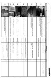
Assembly and Disassembly Procedures 7.1 Assembly Procedures Steps Photo Procedures Part Number Spare Parts List Part Name Q'ty S1 Take a Bracket Chassis Base on a protective cushion and stick a insulator ... function cables to cover page Remark 3 S2 1 2 Power Board 4 Bracket Chassis Base Take a Power board and turn it on the specific positions of Interface board. ACER AL1716W 41 Go to connectors of Bracket Chassis Base. Tear off the tape sticked on the specific position. 7737816630P0A BRACKET ASSY_CHASSIS_ACER T17ANHW_SECC T=0.8mm 1 - Use a Phillipshead...
Assembly and Disassembly Procedures 7.1 Assembly Procedures Steps Photo Procedures Part Number Spare Parts List Part Name Q'ty S1 Take a Bracket Chassis Base on a protective cushion and stick a insulator ... function cables to cover page Remark 3 S2 1 2 Power Board 4 Bracket Chassis Base Take a Power board and turn it on the specific positions of Interface board. ACER AL1716W 41 Go to connectors of Bracket Chassis Base. Tear off the tape sticked on the specific position. 7737816630P0A BRACKET ASSY_CHASSIS_ACER T17ANHW_SECC T=0.8mm 1 - Use a Phillipshead...

AL1716W Service Guide
Page 43
Assembly and Disassembly Procedures (continued) Steps Photo Procedures Part Number Spare Parts List Part Name Q'ty S6 Put a panel on both side and assem ble the LCD panel ... from the holes shown as the photo. - - Torque:=2~3KGF.CM S7 A Turn over the panel and stick a G asket form on the position A. 7742005280P0A SPONGE_GASKET FORM_WHT_W10xH10xL40mm 1 ACER AL1716W 42 Go to cover page Remark S8 M ove the Bracket Chassis M odule on the top of the LCD panel and connect FFC cable to...
Assembly and Disassembly Procedures (continued) Steps Photo Procedures Part Number Spare Parts List Part Name Q'ty S6 Put a panel on both side and assem ble the LCD panel ... from the holes shown as the photo. - - Torque:=2~3KGF.CM S7 A Turn over the panel and stick a G asket form on the position A. 7742005280P0A SPONGE_GASKET FORM_WHT_W10xH10xL40mm 1 ACER AL1716W 42 Go to cover page Remark S8 M ove the Bracket Chassis M odule on the top of the LCD panel and connect FFC cable to...

AL1716W Service Guide
Page 44
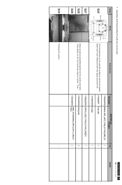
... panel module on the Bracket Chassis module. 7110330052P0A SCREW-MACHING-FLAT HEAD-M3-5-NI 1 Screw Size=M3x5; Assembly and Disassembly Procedures (continued) Steps Photo Procedures Part Number Spare Parts List Part Name Q'ty ACER AL1716W 43 Go to fix it. 7110730082P0A SCREW_MACHINE_NONE_HEX WASHER HEAD_M3_8m m_Fe NI 2 Screw Size=M3x8; Use a Phillips-head...
... panel module on the Bracket Chassis module. 7110330052P0A SCREW-MACHING-FLAT HEAD-M3-5-NI 1 Screw Size=M3x5; Assembly and Disassembly Procedures (continued) Steps Photo Procedures Part Number Spare Parts List Part Name Q'ty ACER AL1716W 43 Go to fix it. 7110730082P0A SCREW_MACHINE_NONE_HEX WASHER HEAD_M3_8m m_Fe NI 2 Screw Size=M3x8; Use a Phillips-head...
AL1716W Service Guide
Page 45
... 1 Stick a Vista label on the Front Bezel with 4 screws. 7115240121P0A SCREW_M4*12_DOUBLE WASHIER 7740412200P0A STAND_BASE_ACER_AL1717_#6800_ABS 94HB ACER AL1716W 44 Go to the order of the number 1 1~2 till two parts firmly attached. 7742612091P0A STAND_COVER_#6800_ABS 94HB_ABS ... is held the right side. 7749106560P0A CUSHION FOAM_EPS_ACER-AL1716W_2160SETS_ L&R_472x117x398(H) 7749600200P0A TAPE_MASKING_PACKING_25mm(w)x45m_LITEON 24- Assembly and Disassembly Procedures (continued) Steps Photo Procedures Part Number Spare Parts List Part Name S19 Turn over the LCD module...
... 1 Stick a Vista label on the Front Bezel with 4 screws. 7115240121P0A SCREW_M4*12_DOUBLE WASHIER 7740412200P0A STAND_BASE_ACER_AL1717_#6800_ABS 94HB ACER AL1716W 44 Go to the order of the number 1 1~2 till two parts firmly attached. 7742612091P0A STAND_COVER_#6800_ABS 94HB_ABS ... is held the right side. 7749106560P0A CUSHION FOAM_EPS_ACER-AL1716W_2160SETS_ L&R_472x117x398(H) 7749600200P0A TAPE_MASKING_PACKING_25mm(w)x45m_LITEON 24- Assembly and Disassembly Procedures (continued) Steps Photo Procedures Part Number Spare Parts List Part Name S19 Turn over the LCD module...
AL1716W Service Guide
Page 46
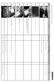
Put accessories on the front and rear sides of carton. ACER AL1716W 45 Go to cover page Remark Assembly and Disassembly Procedures (continued) Steps S26 Photo Procedures Part Number SparePartsList Part Name 7730303323P0A MANUALASSY_ACER_T17AN_AL1716W_EMEA_27L Q'ty 1- S30 Packing the carton. - - -- Then 7749206234P0A CARTON_ACER_T17AN_AL1716W_2160SETS 7735431081P0A Packinglabel 7735431685P0A LABEL_VISTA(...
Put accessories on the front and rear sides of carton. ACER AL1716W 45 Go to cover page Remark Assembly and Disassembly Procedures (continued) Steps S26 Photo Procedures Part Number SparePartsList Part Name 7730303323P0A MANUALASSY_ACER_T17AN_AL1716W_EMEA_27L Q'ty 1- S30 Packing the carton. - - -- Then 7749206234P0A CARTON_ACER_T17AN_AL1716W_2160SETS 7735431081P0A Packinglabel 7735431685P0A LABEL_VISTA(...
AL1716W Service Guide
Page 47
...proper tool. 7735431081P0A Packing label 2 - ACER AL1716W 46 Go to remove the screen protector card. Turn over the LCD monitor (screen faced down), 7730203550P0A CARD_SCREEN PROTECTOR_ACER_T17AA_AL1716W 1 - 1 - S4 2 Disassemble the stand cover. 1 7742612091P0A STAND_COVER_#6800_ABS .... 7749003190P0A BAG_PE_ORDINARY_FOR ACER_L300xW300xT0.05 mm Tear off tapes to cover page Remark Assembly and Disassembly Procedures (continued) 7.2 Disassembly Procedures Steps Photo Procedures Part Number 7749206234P0A Spare Parts Usage Part Name CARTON_ ACER_T17AN_AL1716W_2160SETS Q'...
...proper tool. 7735431081P0A Packing label 2 - ACER AL1716W 46 Go to remove the screen protector card. Turn over the LCD monitor (screen faced down), 7730203550P0A CARD_SCREEN PROTECTOR_ACER_T17AA_AL1716W 1 - 1 - S4 2 Disassemble the stand cover. 1 7742612091P0A STAND_COVER_#6800_ABS .... 7749003190P0A BAG_PE_ORDINARY_FOR ACER_L300xW300xT0.05 mm Tear off tapes to cover page Remark Assembly and Disassembly Procedures (continued) 7.2 Disassembly Procedures Steps Photo Procedures Part Number 7749206234P0A Spare Parts Usage Part Name CARTON_ ACER_T17AN_AL1716W_2160SETS Q'...
AL1716W Service Guide
Page 48
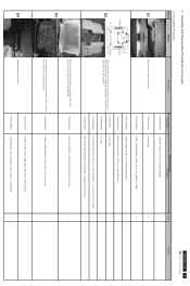
Assembly and Disassembly Procedures (continued) Steps Photo Procedures Part Number Spare Parts Usage Part Name S5 Use a Phillips-head screwdriver unscrew 4 screws to cover page Q'ty Remark 4 Screw ...=6~8KGF.CM S7 S8 Place cloth on the panel where you are release from the Front Bezel. 7140130061P0A T17BNHW-G1(99)_ACER_FUNCTION KEY BD SCREW_MACHINE_WITHOUT_NINDING_M3_6L_BLA ACER AL1716W 47 Go to release the stand base. 7115240121P0A 7740412200P0A SCREW_M4*12_DOUBLE WASHIER STAND_BASE_ACER_AL1717_#6800_ABS 94HB S6 Turn over the LCD monitor (screen faced up...
Assembly and Disassembly Procedures (continued) Steps Photo Procedures Part Number Spare Parts Usage Part Name S5 Use a Phillips-head screwdriver unscrew 4 screws to cover page Q'ty Remark 4 Screw ...=6~8KGF.CM S7 S8 Place cloth on the panel where you are release from the Front Bezel. 7140130061P0A T17BNHW-G1(99)_ACER_FUNCTION KEY BD SCREW_MACHINE_WITHOUT_NINDING_M3_6L_BLA ACER AL1716W 47 Go to release the stand base. 7115240121P0A 7740412200P0A SCREW_M4*12_DOUBLE WASHIER STAND_BASE_ACER_AL1717_#6800_ABS 94HB S6 Turn over the LCD monitor (screen faced up...

AL1716W Service Guide
Page 49
...=M3x5; ACER AL1716W 48 Go to cover page Remark S12 1 S13 Use a Phillips-head screwdriver unscrewed the screw to release the Heat-sink. 7110330052P0A SCREW-MACHING-FLAT HEAD-M3-5-NI 2 Use a Phillips-head screwdriver unscrewed the number 1~2 screws to disassemble the power... Torque:=2~3KGF.CM - - Torque=5~6KGF.CM 2 Screw Size=M3x8; 7. Assembly and Disassembly Procedures (continued) Steps Photo Procedures Part Number Spare Parts Usage Part Name S11 Use both hand to disassemble the LCD panel and Bracket Chassis module. 7110330052P0A SCREW-MACHING-FLAT HEAD-M3-5-NI 3 ...
...=M3x5; ACER AL1716W 48 Go to cover page Remark S12 1 S13 Use a Phillips-head screwdriver unscrewed the screw to release the Heat-sink. 7110330052P0A SCREW-MACHING-FLAT HEAD-M3-5-NI 2 Use a Phillips-head screwdriver unscrewed the number 1~2 screws to disassemble the power... Torque:=2~3KGF.CM - - Torque=5~6KGF.CM 2 Screw Size=M3x8; 7. Assembly and Disassembly Procedures (continued) Steps Photo Procedures Part Number Spare Parts Usage Part Name S11 Use both hand to disassemble the LCD panel and Bracket Chassis module. 7110330052P0A SCREW-MACHING-FLAT HEAD-M3-5-NI 3 ...

AL1716W Service Guide
Page 50
Torque:=7~9KGF.CM - - - - 1 - 1 Screw Size=M4x8; Torque:=7~9KGF.CM ACER AL1716W 49 Go to disassemble the power board. 7116240081P0A SCREW-MACHINE-Star Washer-Pan-M4-8-Zn 7111230061P SCREW-MACHINE-Flat Washer-Pan-M3-6-Zn Q'ty -- Torque:=7~9KGF...FFC Disconnect the FFC, P802, and key function cables to connectors of panel. - - Torque:=7~9KGF.CM 3 Screw Size=M3x6; Assembly and Disassembly Procedures (continued) Steps Photo Procedures Part Number S17 FFC Cable Disconnect the FFC cable to the connector of Interface board. 5113301738P T17ANHW-G1(99)...
Torque:=7~9KGF.CM - - - - 1 - 1 Screw Size=M4x8; Torque:=7~9KGF.CM ACER AL1716W 49 Go to disassemble the power board. 7116240081P0A SCREW-MACHINE-Star Washer-Pan-M4-8-Zn 7111230061P SCREW-MACHINE-Flat Washer-Pan-M3-6-Zn Q'ty -- Torque:=7~9KGF...FFC Disconnect the FFC, P802, and key function cables to connectors of panel. - - Torque:=7~9KGF.CM 3 Screw Size=M3x6; Assembly and Disassembly Procedures (continued) Steps Photo Procedures Part Number S17 FFC Cable Disconnect the FFC cable to the connector of Interface board. 5113301738P T17ANHW-G1(99)...
AL1716x Service Guide
Page 27
NOTE: 1. The monitor surface is susceptible to avoid mismatch when putting back the components. 2. The screws for maintenance and troubleshooting. During the disassembly process, collect the screws with the corresponding components to scratching! Therefore, lay the monitor on how to assemble the monitor for the different components vary ...
NOTE: 1. The monitor surface is susceptible to avoid mismatch when putting back the components. 2. The screws for maintenance and troubleshooting. During the disassembly process, collect the screws with the corresponding components to scratching! Therefore, lay the monitor on how to assemble the monitor for the different components vary ...


