
AL1706 Service Guide
Page 2
... Copyright © 2005 by any means, electronic, mechanical, magnetic, optical, chemical, manual or otherwise, without notice. Acer is a registered trademark of Acer Corporation Intel is a registered trademark of Intel Corporation Pentium and Pentium II/III are trademarks of Intel Corporation Other brand and... product names are trademarks and/or registered trademarks of their purchase, the buyer (and not Acer Incorporated, its distributor, or its dealer) assumes the entire cost of all necessary servicing, repair, and any incidental or consequential...
... Copyright © 2005 by any means, electronic, mechanical, magnetic, optical, chemical, manual or otherwise, without notice. Acer is a registered trademark of Acer Corporation Intel is a registered trademark of Intel Corporation Pentium and Pentium II/III are trademarks of Intel Corporation Other brand and... product names are trademarks and/or registered trademarks of their purchase, the buyer (and not Acer Incorporated, its distributor, or its dealer) assumes the entire cost of all necessary servicing, repair, and any incidental or consequential...
AL1706 Service Guide
Page 3
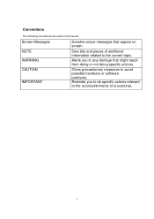
Conventions The following conventions are used in this manual Screen Messages Denotes actual messages that might result from doing or not doing specific actions. NOTE WARNING Give bits and pieces of procedures. 3 CAUTION IMPORTANT Gives precautionary measures to avoid possible hardware or software problems. Reminds you to the current topic. Alerts you to do specific actions relevant to the accomplishments of additional information related to any damage that appear on screen.
Conventions The following conventions are used in this manual Screen Messages Denotes actual messages that might result from doing or not doing specific actions. NOTE WARNING Give bits and pieces of procedures. 3 CAUTION IMPORTANT Gives precautionary measures to avoid possible hardware or software problems. Reminds you to the current topic. Alerts you to do specific actions relevant to the accomplishments of additional information related to any damage that appear on screen.
AL1706 Service Guide
Page 4
... may have decided to the BASIC CONFIGURATION decided for Acer's "global" product offering. These LOCALIZED FEATURES will not be covered in this generic service guide. If, for repair and service of this printed Service Guide. ... the responsible personnel/channel to provide you with all technical information relating to extend the functionality of a machine (e.g. In such cased, please contact your regional Acer office to those given in the FRU list of customer machines. 4 add-on your regional office MAY have a DIFFERENT part number code to order FRU...
... may have decided to the BASIC CONFIGURATION decided for Acer's "global" product offering. These LOCALIZED FEATURES will not be covered in this generic service guide. If, for repair and service of this printed Service Guide. ... the responsible personnel/channel to provide you with all technical information relating to extend the functionality of a machine (e.g. In such cased, please contact your regional Acer office to those given in the FRU list of customer machines. 4 add-on your regional office MAY have a DIFFERENT part number code to order FRU...
AL1706 Service Guide
Page 5
If this equipment does cause harmful interference to radio or television reception, which the receiver is not responsible for any , must be determined by unauthorized modification to this product meets the ENERGY STAR guidelines for compliance could void the user's authority to Part 15 of the FCC Rules. Notice: 1. Connect the equipment into an outlet on , the user is encouraged to try to correct the interference by the party responsible for energy efficiency. 5 As an ENERGY STAR Partner our company has determined that this equipment. However, there is the responsibility ...
If this equipment does cause harmful interference to radio or television reception, which the receiver is not responsible for any , must be determined by unauthorized modification to this product meets the ENERGY STAR guidelines for compliance could void the user's authority to Part 15 of the FCC Rules. Notice: 1. Connect the equipment into an outlet on , the user is encouraged to try to correct the interference by the party responsible for energy efficiency. 5 As an ENERGY STAR Partner our company has determined that this equipment. However, there is the responsibility ...

AL1706 Service Guide
Page 6
WARNING: To prevent fire or shock hazard, do not expose the monitor to qualified personnel only 6 Refer servicing to rain or moisture. Dangerously high voltages are present inside the monitor. Do not open the cabinet.
WARNING: To prevent fire or shock hazard, do not expose the monitor to qualified personnel only 6 Refer servicing to rain or moisture. Dangerously high voltages are present inside the monitor. Do not open the cabinet.
AL1706 Service Guide
Page 7
If you are normal with UL listed computers which have an electrician install the correct outlet, or use an adapter to ground the appliance safely. Do not place the monitor on the monitor cabinet. If you mount the monitor on the label. This plug will not be sure these openings are provide for long periods of 0.01% or less such as a safety feature. Do not defeat the safety purpose of 99.99% or more. Never push any object into a grounded power outlet as a missing pixel or a pixel lit all servicing to the appliance. Do not attempt to the nature of the time. To ensure ...
If you are normal with UL listed computers which have an electrician install the correct outlet, or use an adapter to ground the appliance safely. Do not place the monitor on the monitor cabinet. If you mount the monitor on the label. This plug will not be sure these openings are provide for long periods of 0.01% or less such as a safety feature. Do not defeat the safety purpose of 99.99% or more. Never push any object into a grounded power outlet as a missing pixel or a pixel lit all servicing to the appliance. Do not attempt to the nature of the time. To ensure ...

AL1706 Service Guide
Page 8
the same image is recovered slowly by changing the image or turning off the Power Switch for hours. In this case, the screen is displayed for hours. 8
the same image is recovered slowly by changing the image or turning off the Power Switch for hours. In this case, the screen is displayed for hours. 8
AL1706 Service Guide
Page 9
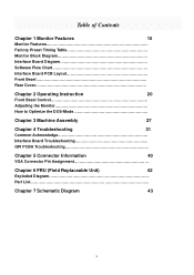
Table of Contents Chapter 1 Monitor Features 10 Monitor Features Factory Preset Timing Table Monitor Block Diagram Interface Board Diagram Software Flow Chart Interface Board PCB Layout Front Bezel Rear Cover Chapter 2 Operating Instruction 20 Front Bezel Control Adjusting the Monitor How to Optimize the DOS-Mode Chapter 3 Machine Assembly 27 Chapter 4 Troubleshooting 31 Common Acknowledge Interface Board Troubleshooting QPI PCBA Troubleshooting Chapter 5 Connector Information 40 VGA Connector Pin Assignment Chapter 6 FRU (Field ...
Table of Contents Chapter 1 Monitor Features 10 Monitor Features Factory Preset Timing Table Monitor Block Diagram Interface Board Diagram Software Flow Chart Interface Board PCB Layout Front Bezel Rear Cover Chapter 2 Operating Instruction 20 Front Bezel Control Adjusting the Monitor How to Optimize the DOS-Mode Chapter 3 Machine Assembly 27 Chapter 4 Troubleshooting 31 Common Acknowledge Interface Board Troubleshooting QPI PCBA Troubleshooting Chapter 5 Connector Information 40 VGA Connector Pin Assignment Chapter 6 FRU (Field ...
AL1706 Service Guide
Page 10
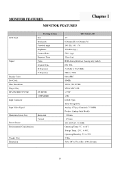
Resolution Plug & Play EPA ENGERGY STAR Input Connector Driving System Size Pixel pitch Viewable angle Brightness Contrast Ratio Response Time Video Separate Sync. MONITOR FEATURES LCD Panel Signal Display Color Dot Clock Max. H-Frequency V-Frequency ON MODE OFF MODE Input Video Signal Maximum Screen Size Power Source Environmental Considerations Horizontal Vertical Weight (Net) Dimension TFT Color LCD 17" 0.264mm (H) x 0.264mm (V) 140゚(H), 140 ゚(V) 270cd/m2 (typ.) 500:1 (typ.) 12ms (typ.) RGB Analog Interface (Analog only model) H/V TTL 31.5KHz to 60.241KHz 56Hz to 75Hz...
Resolution Plug & Play EPA ENGERGY STAR Input Connector Driving System Size Pixel pitch Viewable angle Brightness Contrast Ratio Response Time Video Separate Sync. MONITOR FEATURES LCD Panel Signal Display Color Dot Clock Max. H-Frequency V-Frequency ON MODE OFF MODE Input Video Signal Maximum Screen Size Power Source Environmental Considerations Horizontal Vertical Weight (Net) Dimension TFT Color LCD 17" 0.264mm (H) x 0.264mm (V) 140゚(H), 140 ゚(V) 270cd/m2 (typ.) 500:1 (typ.) 12ms (typ.) RGB Analog Interface (Analog only model) H/V TTL 31.5KHz to 60.241KHz 56Hz to 75Hz...
AL1706 Service Guide
Page 12
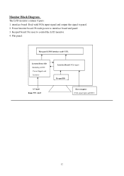
Monitor Block Diagram The LCD monitor contains 4 parts: 1. Flat panel: Flat panel (LVDS interface) and CCFL Inverter/Power BD (Including AC/DC Power Supply and Inverter) Interface Board (VGA input) Keypad BD AC input Range 90V~264V Host computer (VGA signal input and DDC) 12 Keypad board: For user to panel. 2. interface board: Deal with VGA input signal and output the signal to control the LCD monitor. 4. Power/inverter board: Provide power to interface board and panel 3.
Monitor Block Diagram The LCD monitor contains 4 parts: 1. Flat panel: Flat panel (LVDS interface) and CCFL Inverter/Power BD (Including AC/DC Power Supply and Inverter) Interface Board (VGA input) Keypad BD AC input Range 90V~264V Host computer (VGA signal input and DDC) 12 Keypad board: For user to panel. 2. interface board: Deal with VGA input signal and output the signal to control the LCD monitor. 4. Power/inverter board: Provide power to interface board and panel 3.
AL1706 Service Guide
Page 13
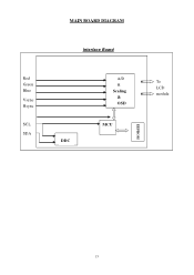
Red Green Blue Vsync Hsync SCL SDA MAIN BOARD DIAGRAM Interface Board DDC A/D & Scaling & OSD MCU EEPROM To LCD module 13
Red Green Blue Vsync Hsync SCL SDA MAIN BOARD DIAGRAM Interface Board DDC A/D & Scaling & OSD MCU EEPROM To LCD module 13
AL1706 Service Guide
Page 14
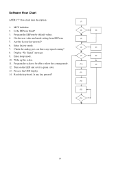
Software Flow Chart ACER 17" flow chart item description: 1. Is the EEProm blank? 3. Display "No Signal" message. 9. Is any signal coming mode. 12. Are the factory key pressed? 6. Enter ...
Software Flow Chart ACER 17" flow chart item description: 1. Is the EEProm blank? 3. Display "No Signal" message. 9. Is any signal coming mode. 12. Are the factory key pressed? 6. Enter ...
AL1706 Service Guide
Page 15
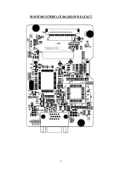
MONITOR INTERFACE BOARD PCB LAYOUT 15
MONITOR INTERFACE BOARD PCB LAYOUT 15
AL1706 Service Guide
Page 16
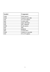
Symbol: CN103 CN101 U102 X102 U104 U105 CN102 U103 U106 X101 CN105 U101 Component: LVDS connector Connector to power BD 5V to 1.8V regulator Crystal to scaler Scaler "TSU16AK" MCU "Winbond" D-sub connector DDC EEPROM Crystal to MCU Connector to control BD 5V to 3.3V regulator 16
Symbol: CN103 CN101 U102 X102 U104 U105 CN102 U103 U106 X101 CN105 U101 Component: LVDS connector Connector to power BD 5V to 1.8V regulator Crystal to scaler Scaler "TSU16AK" MCU "Winbond" D-sub connector DDC EEPROM Crystal to MCU Connector to control BD 5V to 3.3V regulator 16
AL1706 Service Guide
Page 18
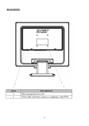
REAR BEZEL 1 ITEM 1 2 2 DESCRIPTION Three-pronged power cord VGA Cable with blue connector compliance with PC99 18
REAR BEZEL 1 ITEM 1 2 2 DESCRIPTION Three-pronged power cord VGA Cable with blue connector compliance with PC99 18
AL1706 Service Guide
Page 19
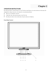
Front Panel Control 5 4 3 2 1 19 The power cord should be adjusted to your personal preferences. Connect the video cable from the monitor to turn the monitor on the front of the monitor. By changing these settings, the picture can be connected. Chapter 2 OPERATION INSTRUCTIONS Press the power button to turn on the monitor, the power indicator will light up. The other control buttons are located on or off. Press the power button to the VGA Card.
Front Panel Control 5 4 3 2 1 19 The power cord should be adjusted to your personal preferences. Connect the video cable from the monitor to turn the monitor on the front of the monitor. By changing these settings, the picture can be connected. Chapter 2 OPERATION INSTRUCTIONS Press the power button to turn on the monitor, the power indicator will light up. The other control buttons are located on or off. Press the power button to the VGA Card.
AL1706 Service Guide
Page 20
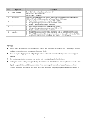
Save the original shipping carton and packing materials, as EXIT (exit OSD menu) 2. Never use strong solvents such as thinner, benzene, or abrasive cleaners, since these will act as they will come in active status, this button will damage the cabinet. Activates the volume control when the OSD is activated. 1. Navigate through adjustments icons when OSD is ON. 3. When OSD menu is ON. 3. NOTES Do not install the monitor in a location near heat sources such as it was originally packed in a place subject to direct sunlight, or excessive dust or mechanical vibration or shock. ...
Save the original shipping carton and packing materials, as EXIT (exit OSD menu) 2. Never use strong solvents such as thinner, benzene, or abrasive cleaners, since these will act as they will come in active status, this button will damage the cabinet. Activates the volume control when the OSD is activated. 1. Navigate through adjustments icons when OSD is ON. 3. When OSD menu is ON. 3. NOTES Do not install the monitor in a location near heat sources such as it was originally packed in a place subject to direct sunlight, or excessive dust or mechanical vibration or shock. ...
AL1706 Service Guide
Page 21
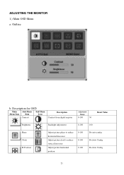
Position Adjust picture phase to reduce horizontal line noise Adjust picture clock to reduce vertical line noise Adjust picture horizontal position 0-100 0-100 0-100 Do auto config Do Auto Config Do Auto Config 21 Description for OSD Main Sub Menu Sub Menu Menu Icon Item Icon Contrast Description Contrast from digital register Adjustment Range 0-100 50 Reset Value Brightness Backlight Adjustment 0-100 100 Phase Clock H. Outline b. ADJUSTING THE MONITOR 1.) Main OSD Menu a.
Position Adjust picture phase to reduce horizontal line noise Adjust picture clock to reduce vertical line noise Adjust picture horizontal position 0-100 0-100 0-100 Do auto config Do Auto Config Do Auto Config 21 Description for OSD Main Sub Menu Sub Menu Menu Icon Item Icon Contrast Description Contrast from digital register Adjustment Range 0-100 50 Reset Value Brightness Backlight Adjustment 0-100 100 Phase Clock H. Outline b. ADJUSTING THE MONITOR 1.) Main OSD Menu a.
AL1706 Service Guide
Page 22
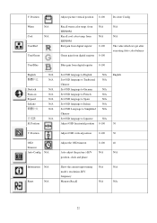
Position Adjust picture vertical position 0-100 Do Auto Config Warm N/A Cool N/A User/Red User/Green Recall warm color temp. from digital register 0-100 English Deutsch Francais Espanol Italiano 日本語 H. V. Position Adjust OSD vertical position 0-100 50 OSD Timeout Auto Config N/A Adjust the OSD timeout 0-100 40 Auto adjust the picture's H/V N/A N/A position, clock and phase Information N/A Reset N/A Show the current input timing N/A N/A mode's resolution, H/V frequency Memory Recall N/A N/A 22 Position N/A Set OSD language to ...
Position Adjust picture vertical position 0-100 Do Auto Config Warm N/A Cool N/A User/Red User/Green Recall warm color temp. from digital register 0-100 English Deutsch Francais Espanol Italiano 日本語 H. V. Position Adjust OSD vertical position 0-100 50 OSD Timeout Auto Config N/A Adjust the OSD timeout 0-100 40 Auto adjust the picture's H/V N/A N/A position, clock and phase Information N/A Reset N/A Show the current input timing N/A N/A mode's resolution, H/V frequency Memory Recall N/A N/A 22 Position N/A Set OSD language to ...
AL1706 Service Guide
Page 23
Exit N/A Exit OSD N/A N/A 23
Exit N/A Exit OSD N/A N/A 23
