
AL1706 Service Guide
Page 2
... reproduced, transmitted, transcribed, stored in a retrieval system, or translated into any language or computer language, I any form or by Acer Incorporated. No part of all necessary servicing, repair, and any incidental or consequential damages reulting from any defect in this guide is ...". Should the programs prove defective following their respective holders. 2 Acer is a registered trademark of Acer Corporation Intel is a registered trademark of Intel Corporation Pentium and Pentium II/III are trademarks of Intel Corporation Other ...
... reproduced, transmitted, transcribed, stored in a retrieval system, or translated into any language or computer language, I any form or by Acer Incorporated. No part of all necessary servicing, repair, and any incidental or consequential damages reulting from any defect in this guide is ...". Should the programs prove defective following their respective holders. 2 Acer is a registered trademark of Acer Corporation Intel is a registered trademark of Intel Corporation Pentium and Pentium II/III are trademarks of Intel Corporation Other ...
AL1706 Service Guide
Page 3
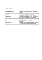
Conventions The following conventions are used in this manual Screen Messages Denotes actual messages that might result from doing or not doing specific actions. Alerts you to do specific actions relevant to the accomplishments of additional information related to any damage that appear on screen. CAUTION IMPORTANT Gives precautionary measures to avoid possible hardware or software problems. Reminds you to the current topic. NOTE WARNING Give bits and pieces of procedures. 3
Conventions The following conventions are used in this manual Screen Messages Denotes actual messages that might result from doing or not doing specific actions. Alerts you to do specific actions relevant to the accomplishments of additional information related to any damage that appear on screen. CAUTION IMPORTANT Gives precautionary measures to avoid possible hardware or software problems. Reminds you to the current topic. NOTE WARNING Give bits and pieces of procedures. 3
AL1706 Service Guide
Page 4
...PARTS, that you should check the most up-to provide you with further technical details. 2. You MUST use the list provided by your Acer office may have decided to order FRU parts for repair and service of a machine (e.g. This Service Guide provides you with all technical ...information relating to those given in this printed Service Guide. If, for Acer's "global" product offering. For ACER-AUTHORIZED SERVICE PROVIEDERS, your regional Acer office to extend the functionality of customer machines. 4
...PARTS, that you should check the most up-to provide you with further technical details. 2. You MUST use the list provided by your Acer office may have decided to order FRU parts for repair and service of a machine (e.g. This Service Guide provides you with all technical ...information relating to those given in this printed Service Guide. If, for Acer's "global" product offering. For ACER-AUTHORIZED SERVICE PROVIEDERS, your regional Acer office to extend the functionality of customer machines. 4
AL1706 Service Guide
Page 5
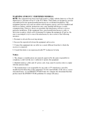
Consult the dealer or an experienced radio/TV technician for a Class B digital device, pursuant to Part 15 of the FCC Rules. WARNING (FOR FCC CERTIFIED MODELS) NOTE: This equipment has been tested and found to comply with the limits for help. Reorient or relocate the receiving antenna. 2. Increase the separation between the equipment and receiver. 3. The changes or modifications not expressly approved by one or more of the user to correct the interference by the party responsible for energy efficiency. 5 Shielded interface cables and AC power cord, if any radio or TV ...
Consult the dealer or an experienced radio/TV technician for a Class B digital device, pursuant to Part 15 of the FCC Rules. WARNING (FOR FCC CERTIFIED MODELS) NOTE: This equipment has been tested and found to comply with the limits for help. Reorient or relocate the receiving antenna. 2. Increase the separation between the equipment and receiver. 3. The changes or modifications not expressly approved by one or more of the user to correct the interference by the party responsible for energy efficiency. 5 Shielded interface cables and AC power cord, if any radio or TV ...

AL1706 Service Guide
Page 6
Do not open the cabinet. Refer servicing to rain or moisture. Dangerously high voltages are present inside the monitor. WARNING: To prevent fire or shock hazard, do not expose the monitor to qualified personnel only 6
Do not open the cabinet. Refer servicing to rain or moisture. Dangerously high voltages are present inside the monitor. WARNING: To prevent fire or shock hazard, do not expose the monitor to qualified personnel only 6
AL1706 Service Guide
Page 7
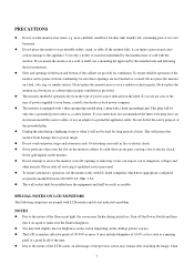
PRECAUTIONS Do not use an adapter to ground the appliance safely. User only a trolley or stand recommended by the manufacturer and following symptoms are not blocked or covered. If your dealer or local power company. Overloading can result in a bookcase or cabinet unless proper ventilation is equipped with a three-pronged grounded plug, a plug with UL listed computers which have an electrician install the correct outlet, or use the monitor near a bathtub, washbowl, kitchen sink, laundry tub, swimming pool or in the back and bottom of power source indicated on a wall ...
PRECAUTIONS Do not use an adapter to ground the appliance safely. User only a trolley or stand recommended by the manufacturer and following symptoms are not blocked or covered. If your dealer or local power company. Overloading can result in a bookcase or cabinet unless proper ventilation is equipped with a three-pronged grounded plug, a plug with UL listed computers which have an electrician install the correct outlet, or use the monitor near a bathtub, washbowl, kitchen sink, laundry tub, swimming pool or in the back and bottom of power source indicated on a wall ...

AL1706 Service Guide
Page 8
In this case, the screen is displayed for hours. 8 the same image is recovered slowly by changing the image or turning off the Power Switch for hours.
In this case, the screen is displayed for hours. 8 the same image is recovered slowly by changing the image or turning off the Power Switch for hours.
AL1706 Service Guide
Page 9
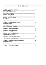
Table of Contents Chapter 1 Monitor Features 10 Monitor Features Factory Preset Timing Table Monitor Block Diagram Interface Board Diagram Software Flow Chart Interface Board PCB Layout Front Bezel Rear Cover Chapter 2 Operating Instruction 20 Front Bezel Control Adjusting the Monitor How to Optimize the DOS-Mode Chapter 3 Machine Assembly 27 Chapter 4 Troubleshooting 31 Common Acknowledge Interface Board Troubleshooting QPI PCBA Troubleshooting Chapter 5 Connector Information 40 VGA Connector Pin Assignment Chapter 6 FRU (Field ...
Table of Contents Chapter 1 Monitor Features 10 Monitor Features Factory Preset Timing Table Monitor Block Diagram Interface Board Diagram Software Flow Chart Interface Board PCB Layout Front Bezel Rear Cover Chapter 2 Operating Instruction 20 Front Bezel Control Adjusting the Monitor How to Optimize the DOS-Mode Chapter 3 Machine Assembly 27 Chapter 4 Troubleshooting 31 Common Acknowledge Interface Board Troubleshooting QPI PCBA Troubleshooting Chapter 5 Connector Information 40 VGA Connector Pin Assignment Chapter 6 FRU (Field ...
AL1706 Service Guide
Page 10
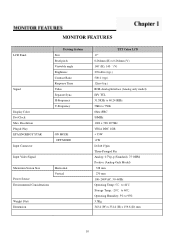
Resolution Plug & Play EPA ENGERGY STAR Input Connector Driving System Size Pixel pitch Viewable angle Brightness Contrast Ratio Response Time Video Separate Sync. MONITOR FEATURES LCD Panel Signal Display Color Dot Clock Max. H-Frequency V-Frequency ON MODE OFF MODE Input Video Signal Maximum Screen Size Power Source Environmental Considerations Horizontal Vertical Weight (Net) Dimension TFT Color LCD 17" 0.264mm (H) x 0.264mm (V) 140゚(H), 140 ゚(V) 270cd/m2 (typ.) 500:1 (typ.) 12ms (typ.) RGB Analog Interface (Analog only model) H/V TTL 31.5KHz to 60.241KHz 56Hz to 75Hz ...
Resolution Plug & Play EPA ENGERGY STAR Input Connector Driving System Size Pixel pitch Viewable angle Brightness Contrast Ratio Response Time Video Separate Sync. MONITOR FEATURES LCD Panel Signal Display Color Dot Clock Max. H-Frequency V-Frequency ON MODE OFF MODE Input Video Signal Maximum Screen Size Power Source Environmental Considerations Horizontal Vertical Weight (Net) Dimension TFT Color LCD 17" 0.264mm (H) x 0.264mm (V) 140゚(H), 140 ゚(V) 270cd/m2 (typ.) 500:1 (typ.) 12ms (typ.) RGB Analog Interface (Analog only model) H/V TTL 31.5KHz to 60.241KHz 56Hz to 75Hz ...
AL1706 Service Guide
Page 12
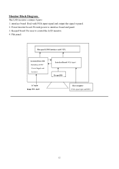
Flat panel: Flat panel (LVDS interface) and CCFL Inverter/Power BD (Including AC/DC Power Supply and Inverter) Interface Board (VGA input) Keypad BD AC input Range 90V~264V Host computer (VGA signal input and DDC) 12 interface board: Deal with VGA input signal and output the signal to interface board and panel 3. Power/inverter board: Provide power to panel. 2. Keypad board: For user to control the LCD monitor. 4. Monitor Block Diagram The LCD monitor contains 4 parts: 1.
Flat panel: Flat panel (LVDS interface) and CCFL Inverter/Power BD (Including AC/DC Power Supply and Inverter) Interface Board (VGA input) Keypad BD AC input Range 90V~264V Host computer (VGA signal input and DDC) 12 interface board: Deal with VGA input signal and output the signal to interface board and panel 3. Power/inverter board: Provide power to panel. 2. Keypad board: For user to control the LCD monitor. 4. Monitor Block Diagram The LCD monitor contains 4 parts: 1.
AL1706 Service Guide
Page 13
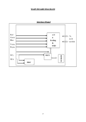
Red Green Blue Vsync Hsync SCL SDA MAIN BOARD DIAGRAM Interface Board DDC A/D & Scaling & OSD MCU EEPROM To LCD module 13
Red Green Blue Vsync Hsync SCL SDA MAIN BOARD DIAGRAM Interface Board DDC A/D & Scaling & OSD MCU EEPROM To LCD module 13
AL1706 Service Guide
Page 14
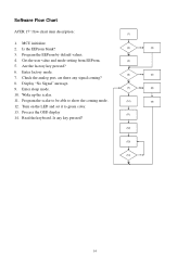
...) (12) (13) (14) Y No 14 Read the keyboard. Enter sleep mode. 10. Process the OSD display 14. Are the factory key pressed? 6. Software Flow Chart ACER 17" flow chart item description: 1. Enter factory mode. 7. Program the EEProm by default values. 4.
...) (12) (13) (14) Y No 14 Read the keyboard. Enter sleep mode. 10. Process the OSD display 14. Are the factory key pressed? 6. Software Flow Chart ACER 17" flow chart item description: 1. Enter factory mode. 7. Program the EEProm by default values. 4.
AL1706 Service Guide
Page 15
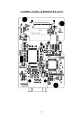
MONITOR INTERFACE BOARD PCB LAYOUT 15
MONITOR INTERFACE BOARD PCB LAYOUT 15
AL1706 Service Guide
Page 16
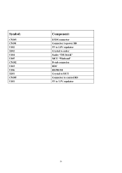
Symbol: CN103 CN101 U102 X102 U104 U105 CN102 U103 U106 X101 CN105 U101 Component: LVDS connector Connector to power BD 5V to 1.8V regulator Crystal to scaler Scaler "TSU16AK" MCU "Winbond" D-sub connector DDC EEPROM Crystal to MCU Connector to control BD 5V to 3.3V regulator 16
Symbol: CN103 CN101 U102 X102 U104 U105 CN102 U103 U106 X101 CN105 U101 Component: LVDS connector Connector to power BD 5V to 1.8V regulator Crystal to scaler Scaler "TSU16AK" MCU "Winbond" D-sub connector DDC EEPROM Crystal to MCU Connector to control BD 5V to 3.3V regulator 16
AL1706 Service Guide
Page 18
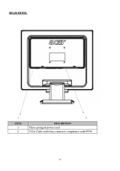
REAR BEZEL 1 ITEM 1 2 2 DESCRIPTION Three-pronged power cord VGA Cable with blue connector compliance with PC99 18
REAR BEZEL 1 ITEM 1 2 2 DESCRIPTION Three-pronged power cord VGA Cable with blue connector compliance with PC99 18
AL1706 Service Guide
Page 19
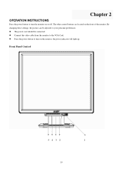
Connect the video cable from the monitor to your personal preferences. Front Panel Control 5 4 3 2 1 19 Press the power button to turn the monitor on or off. By changing these settings, the picture can be connected. The other control buttons are located on the monitor, the power indicator will light up. Chapter 2 OPERATION INSTRUCTIONS Press the power button to turn on the front of the monitor. The power cord should be adjusted to the VGA Card.
Connect the video cable from the monitor to your personal preferences. Front Panel Control 5 4 3 2 1 19 Press the power button to turn the monitor on or off. By changing these settings, the picture can be connected. The other control buttons are located on the monitor, the power indicator will light up. Chapter 2 OPERATION INSTRUCTIONS Press the power button to turn on the front of the monitor. The power cord should be adjusted to the VGA Card.
AL1706 Service Guide
Page 20
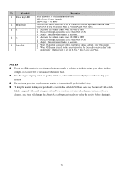
Activates the volume control when the OSD is activated. 1. Adjust a function when function is OFF. 2. Adjust a function when function is in active status, this button for 2seconds to activate the "Auto Adjustment" which is ON. 3. Save the original shipping carton and packing materials, as they will come in a place subject to set the H.Pos., V Pos., Clock and Phase. For maximum protection, repackage your monitor. Never use strong solvents such as radiators or air ducts, or in handy if you ever have to ship your monitor as EXIT (exit OSD menu) 2. To keep the ...
Activates the volume control when the OSD is activated. 1. Adjust a function when function is OFF. 2. Adjust a function when function is in active status, this button for 2seconds to activate the "Auto Adjustment" which is ON. 3. Save the original shipping carton and packing materials, as they will come in a place subject to set the H.Pos., V Pos., Clock and Phase. For maximum protection, repackage your monitor. Never use strong solvents such as radiators or air ducts, or in handy if you ever have to ship your monitor as EXIT (exit OSD menu) 2. To keep the ...
AL1706 Service Guide
Page 21
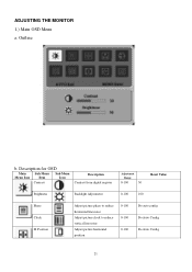
Outline b. Position Adjust picture phase to reduce horizontal line noise Adjust picture clock to reduce vertical line noise Adjust picture horizontal position 0-100 0-100 0-100 Do auto config Do Auto Config Do Auto Config 21 ADJUSTING THE MONITOR 1.) Main OSD Menu a. Description for OSD Main Sub Menu Sub Menu Menu Icon Item Icon Contrast Description Contrast from digital register Adjustment Range 0-100 50 Reset Value Brightness Backlight Adjustment 0-100 100 Phase Clock H.
Outline b. Position Adjust picture phase to reduce horizontal line noise Adjust picture clock to reduce vertical line noise Adjust picture horizontal position 0-100 0-100 0-100 Do auto config Do Auto Config Do Auto Config 21 ADJUSTING THE MONITOR 1.) Main OSD Menu a. Description for OSD Main Sub Menu Sub Menu Menu Icon Item Icon Contrast Description Contrast from digital register Adjustment Range 0-100 50 Reset Value Brightness Backlight Adjustment 0-100 100 Phase Clock H.
AL1706 Service Guide
Page 22
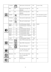
V. from digital register 0-100 English Deutsch Francais Espanol Italiano 日本語 H. Position N/A Set OSD language to English N/A English N/A Set OSD language to Traditional N/A Chinese N/A Set OSD language to German N/A N/A Set OSD language to French N/A N/A Set OSD language to Spain N/A N/A Set OSD language to Italian N/A N/A Set OSD Language to Simplified N/A Chinese N/A Set OSD language to Japanese N/A Adjust OSD horizontal position 0-100 50 V. Position Adjust OSD vertical position 0-100 50 OSD Timeout Auto Config N/A Adjust the OSD ...
V. from digital register 0-100 English Deutsch Francais Espanol Italiano 日本語 H. Position N/A Set OSD language to English N/A English N/A Set OSD language to Traditional N/A Chinese N/A Set OSD language to German N/A N/A Set OSD language to French N/A N/A Set OSD language to Spain N/A N/A Set OSD language to Italian N/A N/A Set OSD Language to Simplified N/A Chinese N/A Set OSD language to Japanese N/A Adjust OSD horizontal position 0-100 50 V. Position Adjust OSD vertical position 0-100 50 OSD Timeout Auto Config N/A Adjust the OSD ...
AL1706 Service Guide
Page 23
Exit N/A Exit OSD N/A N/A 23
Exit N/A Exit OSD N/A N/A 23
