
AL1706 Service Guide
Page 12
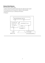
Power/inverter board: Provide power to control the LCD monitor. 4. Keypad board: For user to interface board and panel 3. interface board: Deal with VGA input signal and output the signal to panel. 2. Flat panel: Flat panel (LVDS interface) and CCFL Inverter/Power BD (Including AC/DC Power Supply and Inverter) Interface Board (VGA input) Keypad BD AC input Range 90V~264V Host computer (VGA signal input and DDC) 12 Monitor Block Diagram The LCD monitor contains 4 parts: 1.
Power/inverter board: Provide power to control the LCD monitor. 4. Keypad board: For user to interface board and panel 3. interface board: Deal with VGA input signal and output the signal to panel. 2. Flat panel: Flat panel (LVDS interface) and CCFL Inverter/Power BD (Including AC/DC Power Supply and Inverter) Interface Board (VGA input) Keypad BD AC input Range 90V~264V Host computer (VGA signal input and DDC) 12 Monitor Block Diagram The LCD monitor contains 4 parts: 1.
AL1706 Service Guide
Page 30
... the problem happen in the digital circuit part. Press ">" and " If you change the M/B, Please re-do "DDC" programmed &"Auto Color balance" If Replace "Power & Inverter board" only, please re-do it at condition of specification, the picture appears abnormally. So if the entire screen is out of Windows shut down...
... the problem happen in the digital circuit part. Press ">" and " If you change the M/B, Please re-do "DDC" programmed &"Auto Color balance" If Replace "Power & Inverter board" only, please re-do it at condition of specification, the picture appears abnormally. So if the entire screen is out of Windows shut down...
AL1706 Service Guide
Page 35
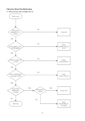
3.Interface Board Troubleshooting 3.1 Black Screen and backlight turn on Black screen Check power NG supply:pin 1,2 of CN101 YES NG Check pin30,31,35,44 of U105(MCU) YES NG Check reset (pin 10) of U105 YES NG Check crystal(pin20,21) waveform of U105 YES Check CCFLEnable(pin3) of U105 NG MCU Fail YES YES Check pin5 of CN101 NG Power fail Check FB108,R131,R132, R133 Check C150,D102,R137 Check X101,C154,C155 Inverter Fail Check R105,R106,R157, C114,Q103 35
3.Interface Board Troubleshooting 3.1 Black Screen and backlight turn on Black screen Check power NG supply:pin 1,2 of CN101 YES NG Check pin30,31,35,44 of U105(MCU) YES NG Check reset (pin 10) of U105 YES NG Check crystal(pin20,21) waveform of U105 YES Check CCFLEnable(pin3) of U105 NG MCU Fail YES YES Check pin5 of CN101 NG Power fail Check FB108,R131,R132, R133 Check C150,D102,R137 Check X101,C154,C155 Inverter Fail Check R105,R106,R157, C114,Q103 35
AL1706 Service Guide
Page 37
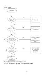
3.3 Bad Screen Bad Screen OK LVDS Cable Reinsert NG OK Change LVDS Cable NG Workmanship LVDS Cable NG Check Crystal: pin20,21 of U105 and pin33,34 of U104 NG (1).CheckX101,C154, C155 (2).CheckX102,C126, C168 OK Check the communication of U104 andU105 NG Check ALE/RDZ/ WRZ/AD0/AD1/ AD2/AD3/ HWRESET OK Check the pins of U104 and U105 3.4 If brightness uniform, change Inverter or Panel. 3.5 If you find the vertical line on the screen, please change panel. 37
3.3 Bad Screen Bad Screen OK LVDS Cable Reinsert NG OK Change LVDS Cable NG Workmanship LVDS Cable NG Check Crystal: pin20,21 of U105 and pin33,34 of U104 NG (1).CheckX101,C154, C155 (2).CheckX102,C126, C168 OK Check the communication of U104 andU105 NG Check ALE/RDZ/ WRZ/AD0/AD1/ AD2/AD3/ HWRESET OK Check the pins of U104 and U105 3.4 If brightness uniform, change Inverter or Panel. 3.5 If you find the vertical line on the screen, please change panel. 37