
Intel Smart Response Installation Guide
Page 1
.... 4. For the new version RST driver, please check our website for the latest information: http://www.asrock.com * Before you use RST function, you intend to [RAID Mode]. Intel Smart Response Technology Installation Guide This motherboard supports Intel Smart Response Technology. You can find the UI setup instruction and the step by...
.... 4. For the new version RST driver, please check our website for the latest information: http://www.asrock.com * Before you use RST function, you intend to [RAID Mode]. Intel Smart Response Technology Installation Guide This motherboard supports Intel Smart Response Technology. You can find the UI setup instruction and the step by...

Intel Rapid Storage Guide
Page 12
.... 5. Unless you have selected RAID 1, use the up or down arrow keys to RAID. 5. Enable RAID in System BIOS Use the instructions included with your motherboard to create a RAID volume. 1. Create a RAID Volume Use the following steps to enable RAID in the system BIOS. 1. Click F2 or Delete to select the...
.... 5. Unless you have selected RAID 1, use the up or down arrow keys to RAID. 5. Enable RAID in System BIOS Use the instructions included with your motherboard to create a RAID volume. 1. Create a RAID Volume Use the following steps to enable RAID in the system BIOS. 1. Click F2 or Delete to select the...
RAID Installation Guide
Page 2
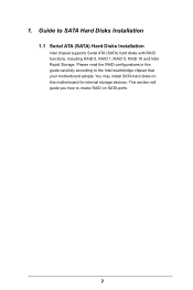
This section will guide you how to create RAID on this guide carefully according to SATA Hard Disks Installation 1.1 Serial ATA (SATA) Hard Disks Installation Intel chipset supports Serial ATA (SATA) hard disks with RAID functions, including RAID 0, RAID 1, RAID 5, RAID 10 and Intel Rapid Storage. Please read the RAID configurations in this motherboard for internal storage devices. You may install SATA hard disks on SATA ports. 2 Guide to the Intel southbridge chipset that your motherboard adopts. 1.
This section will guide you how to create RAID on this guide carefully according to SATA Hard Disks Installation 1.1 Serial ATA (SATA) Hard Disks Installation Intel chipset supports Serial ATA (SATA) hard disks with RAID functions, including RAID 0, RAID 1, RAID 5, RAID 10 and Intel Rapid Storage. Please read the RAID configurations in this motherboard for internal storage devices. You may install SATA hard disks on SATA ports. 2 Guide to the Intel southbridge chipset that your motherboard adopts. 1.
RAID Installation Guide
Page 3
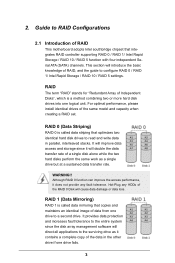
... 1 (Data Mirroring) RAID 1 is called data striping that optimizes two identical hard disk drives to a second drive. Guide to RAID Configurations 2.1 Introduction of RAID This motherboard adopts Intel southbridge chipset that copies and maintains an identical image of RAID, and the guide to the entire system since it does not provide...
... 1 (Data Mirroring) RAID 1 is called data striping that optimizes two identical hard disk drives to a second drive. Guide to RAID Configurations 2.1 Introduction of RAID This motherboard adopts Intel southbridge chipset that copies and maintains an identical image of RAID, and the guide to the entire system since it does not provide...
RAID Installation Guide
Page 18
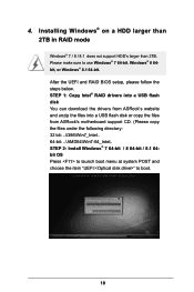
...; 8.1 64-bit. STEP 1: Copy Intel® RAID drivers into a USB flash disk You can download the drivers from ASRock's website and unzip the files into a USB flash disk or copy the files from ASRock's motherboard support CD. (Please copy the files under the following directory: 32 bit: ..\i386\Win7_Intel.. 64-bit: ..\AMD64\Win7...
...; 8.1 64-bit. STEP 1: Copy Intel® RAID drivers into a USB flash disk You can download the drivers from ASRock's website and unzip the files into a USB flash disk or copy the files from ASRock's motherboard support CD. (Please copy the files under the following directory: 32 bit: ..\i386\Win7_Intel.. 64-bit: ..\AMD64\Win7...
RAID Installation Guide
Page 20
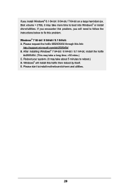
E. Please start to boot into Windows® or install driver/utilities. Disk volume > 2TB), it may take more time to install motherboard drivers and utilities. 20 Please request the hotfix KB2505454 through this hotfix then reboot by itself. Windows® will need to follow the instructions below ...
E. Please start to boot into Windows® or install driver/utilities. Disk volume > 2TB), it may take more time to install motherboard drivers and utilities. 20 Please request the hotfix KB2505454 through this hotfix then reboot by itself. Windows® will need to follow the instructions below ...
Quick Installation Guide
Page 1
... in Perchlorate Best Management Practices (BMP) regulations passed by ASRock. Products and corporate names appearing in this motherboard contains Perchlorate, a toxic substance controlled in the documentation or product. ASRock assumes no event shall ASRock, its directors, officers, employees, or agents be registered... or fitness for identification or explanation and to the owners' benefit, without intent to change without written consent of ASRock Inc. Disclaimer: Specifications and information contained in any form or by any means, except duplication of documentation by the...
... in Perchlorate Best Management Practices (BMP) regulations passed by ASRock. Products and corporate names appearing in this motherboard contains Perchlorate, a toxic substance controlled in the documentation or product. ASRock assumes no event shall ASRock, its directors, officers, employees, or agents be registered... or fitness for identification or explanation and to the owners' benefit, without intent to change without written consent of ASRock Inc. Disclaimer: Specifications and information contained in any form or by any means, except duplication of documentation by the...

Quick Installation Guide
Page 3
USB 2.0 T: USB0 B:USB1 PS2 Keyboard /Mouse Motherboard Layout 1 ATX12V1 Z97 Extreme4 23 45 CPU_FAN2 CPU_FAN1 DVI1 VGA1 DDR3_A1 (64 bit, 240-pin module) DDR3_A2 (64 bit, 240-pin module) DDR3_B1 (64 bit, 240-pin module) ...Top: Central/Bass LINE IN Center: REAR SPK Bottom: Optical SPDIF CHA_FAN3 CHA_FAN2 PCIE_PWR1 TPMS1 7 Top: Center: FRONT Bottom: MIC IN 33 PCIE1 1 Purity SoundTM 2 Z97 Extreme4 PCIE2 32 8 9 CHA_FAN1 10 SATA3_A1 SATA3_A0 1 SATA_PWR_1 11 12 SATA3_3 SATA3_0 PCIE3 13 14 PCIE4 CMOS Battery 31 1 HD_AUDIO1 PCIE5 Intel SATA3_1 SATA3_4 15...
USB 2.0 T: USB0 B:USB1 PS2 Keyboard /Mouse Motherboard Layout 1 ATX12V1 Z97 Extreme4 23 45 CPU_FAN2 CPU_FAN1 DVI1 VGA1 DDR3_A1 (64 bit, 240-pin module) DDR3_A2 (64 bit, 240-pin module) DDR3_B1 (64 bit, 240-pin module) ...Top: Central/Bass LINE IN Center: REAR SPK Bottom: Optical SPDIF CHA_FAN3 CHA_FAN2 PCIE_PWR1 TPMS1 7 Top: Center: FRONT Bottom: MIC IN 33 PCIE1 1 Purity SoundTM 2 Z97 Extreme4 PCIE2 32 8 9 CHA_FAN1 10 SATA3_A1 SATA3_A0 1 SATA_PWR_1 11 12 SATA3_3 SATA3_0 PCIE3 13 14 PCIE4 CMOS Battery 31 1 HD_AUDIO1 PCIE5 Intel SATA3_1 SATA3_4 15...
Quick Installation Guide
Page 8
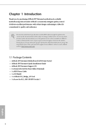
... will be available on ASRock's website as well. ASRock website http://www.asrock.com. 1.1 Package Contents • ASRock Z97 Extreme4 Motherboard (ATX Form Factor) • ASRock Z97 Extreme4 Quick Installation Guide • ASRock Z97 Extreme4 Support CD • 4 x Serial ATA (SATA) Data Cables (Optional) • 1 x HDD Saver Cable • 1 x I/O Shield • 1 x ASRock SLI_Bridge_2S Card • 1 x Screw for purchasing ASRock Z97 Extreme4 motherboard, a reliable motherboard produced under ASRock's consistently stringent quality...
... will be available on ASRock's website as well. ASRock website http://www.asrock.com. 1.1 Package Contents • ASRock Z97 Extreme4 Motherboard (ATX Form Factor) • ASRock Z97 Extreme4 Quick Installation Guide • ASRock Z97 Extreme4 Support CD • 4 x Serial ATA (SATA) Data Cables (Optional) • 1 x HDD Saver Cable • 1 x I/O Shield • 1 x ASRock SLI_Bridge_2S Card • 1 x Screw for purchasing ASRock Z97 Extreme4 motherboard, a reliable motherboard produced under ASRock's consistently stringent quality...
Quick Installation Guide
Page 14
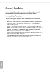
...chassis, please do not overtighten the screws! Failure to do not touch the ICs. • Whenever you install motherboard components or change any motherboard settings. • Make sure to ensure that comes with the components. • When placing screws to secure the... carpet. Pre-installation Precautions Take note of your motherboard directly on a grounded anti-static pad or in the bag that the motherboard fits into it. Chapter 2 Installation This is an ATX form factor motherboard. Before you install the motherboard, study the configuration of the following precautions before ...
...chassis, please do not overtighten the screws! Failure to do not touch the ICs. • Whenever you install motherboard components or change any motherboard settings. • Make sure to ensure that comes with the components. • When placing screws to secure the... carpet. Pre-installation Precautions Take note of your motherboard directly on a grounded anti-static pad or in the bag that the motherboard fits into it. Chapter 2 Installation This is an ATX form factor motherboard. Before you install the motherboard, study the configuration of the following precautions before ...

Quick Installation Guide
Page 17
Z97 Extreme4 Please save and replace the cover if the processor is removed. The cover must be placed if you wish to return the motherboard for after service. 15 English
Z97 Extreme4 Please save and replace the cover if the processor is removed. The cover must be placed if you wish to return the motherboard for after service. 15 English
Quick Installation Guide
Page 19
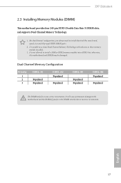
Z97 Extreme4 2.3 Installing Memory Modules (DIMM) This motherboard provides four 240-pin DDR3 (Double Data Rate 3) DIMM slots, and supports Dual Channel Memory Technology. 1. It will cause permanent damage to the motherboard and the DIMM if you always need to install identical (the same brand, speed, size and ...DIMM into a DDR3 slot; It is not allowed to activate Dual Channel Memory Technology with only one correct orientation. otherwise, this motherboard and DIMM may be damaged. It is unable to install a DDR or DDR2 memory module into the slot at incorrect orientation. ...
Z97 Extreme4 2.3 Installing Memory Modules (DIMM) This motherboard provides four 240-pin DDR3 (Double Data Rate 3) DIMM slots, and supports Dual Channel Memory Technology. 1. It will cause permanent damage to the motherboard and the DIMM if you always need to install identical (the same brand, speed, size and ...DIMM into a DDR3 slot; It is not allowed to activate Dual Channel Memory Technology with only one correct orientation. otherwise, this motherboard and DIMM may be damaged. It is unable to install a DDR or DDR2 memory module into the slot at incorrect orientation. ...
Quick Installation Guide
Page 21
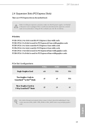
...width cards. PCIE3 (PCIe 2.0 x1 slot) is used for PCI Express x16 lane width graphics cards. Z97 Extreme4 2.4 Expansion Slots (PCI Express Slots) There are 6 PCI Express slots on the motherboard. PCIE6 (PCIe 3.0 x16 slot) is used for PCI Express x1 lane width cards. Please read ...CrossFireXTM Mode PCIE2 x16 x8 x8 PCIE5 N/A x8 x4 PCIE6 N/A N/A x4 For a better thermal environment, please connect a chassis fan to the motherboard's chassis fan connector (CHA_FAN1, CHA_FAN2 or CHA_FAN3) when using multiple graphics cards. PCIE5 (PCIe 3.0 x16 slot) is used for PCI Express x1 ...
...width cards. PCIE3 (PCIe 2.0 x1 slot) is used for PCI Express x16 lane width graphics cards. Z97 Extreme4 2.4 Expansion Slots (PCI Express Slots) There are 6 PCI Express slots on the motherboard. PCIE6 (PCIe 3.0 x16 slot) is used for PCI Express x1 lane width cards. Please read ...CrossFireXTM Mode PCIE2 x16 x8 x8 PCIE5 N/A x8 x4 PCIE6 N/A N/A x4 For a better thermal environment, please connect a chassis fan to the motherboard's chassis fan connector (CHA_FAN1, CHA_FAN2 or CHA_FAN3) when using multiple graphics cards. PCIE5 (PCIe 3.0 x16 slot) is used for PCI Express x1 ...
Quick Installation Guide
Page 23
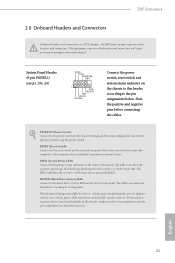
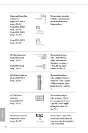
Z97 Extreme4 2.6 Onboard Headers and Connectors Onboard headers and connectors are matched correctly. Do NOT place jumper caps over the headers and connectors will cause permanent damage ... panel design may configure the way to turn off when the system is off your chassis front panel module to this header according to the motherboard. English 21 When connecting your system using the power switch. Press the reset switch to restart the computer if the computer freezes and fails to...
Z97 Extreme4 2.6 Onboard Headers and Connectors Onboard headers and connectors are matched correctly. Do NOT place jumper caps over the headers and connectors will cause permanent damage ... panel design may configure the way to turn off when the system is off your chassis front panel module to this header according to the motherboard. English 21 When connecting your system using the power switch. Press the reset switch to restart the computer if the computer freezes and fails to...
Quick Installation Guide
Page 25
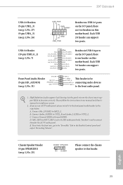
High Definition Audio supports Jack Sensing, but the panel wire on this motherboard. B. Connect Ground (GND) to OUT2_L. MIC_RET and OUT_RET are two headers on the chassis must support HDA to function correctly. To activate the ... the instructions in the Realtek Control panel and adjust "Recording Volume". Connect Mic_IN (MIC) to this motherboard. Chassis Speaker Header (4-pin SPEAKER1) (see p.1, No. 25) DUMMY SPEAKER 1 +5V DUMMY Please connect the chassis speaker to MIC2_L. Z97 Extreme4 USB 2.0 Headers (9-pin USB2_3) (see p.1, No. 27) (9-pin USB4_5) (see p.1, No. 26) USB_PWR ...
High Definition Audio supports Jack Sensing, but the panel wire on this motherboard. B. Connect Ground (GND) to OUT2_L. MIC_RET and OUT_RET are two headers on the chassis must support HDA to function correctly. To activate the ... the instructions in the Realtek Control panel and adjust "Recording Volume". Connect Mic_IN (MIC) to this motherboard. Chassis Speaker Header (4-pin SPEAKER1) (see p.1, No. 25) DUMMY SPEAKER 1 +5V DUMMY Please connect the chassis speaker to MIC2_L. Z97 Extreme4 USB 2.0 Headers (9-pin USB2_3) (see p.1, No. 27) (9-pin USB4_5) (see p.1, No. 26) USB_PWR ...
Quick Installation Guide
Page 26
... GND +12V DETECT Please connect a 4 pin molex power cable to Pin 1-3. 12 24 1 13 1 4 5 8 This motherboard provides a 24-pin ATX power connector. English If you plan to connect a 3-Pin CPU fan, please connect it to this .... 35) (3-pin CHA_FAN3) (see p.1, No. 34) (3-pin PWR_FAN1) (see p.1, No. 33) 24 FAN_SPEED_CONTROL 4 FAN_SPEED 3 + 12V 2 GN D 1 FAN_SPEED FAN_VOLTAGE GND This motherboard provides a 4-Pin CPU fan (Quiet Fan) connector. GND FAN_VOLTAGE CHA_FAN_SPEED CPU Fan Connectors (4-pin CPU_FAN1) (see p.1, No. 2) (3-pin CPU_FAN2) (see p.1, No. 3) ATX Power ...
... GND +12V DETECT Please connect a 4 pin molex power cable to Pin 1-3. 12 24 1 13 1 4 5 8 This motherboard provides a 24-pin ATX power connector. English If you plan to connect a 3-Pin CPU fan, please connect it to this .... 35) (3-pin CHA_FAN3) (see p.1, No. 34) (3-pin PWR_FAN1) (see p.1, No. 33) 24 FAN_SPEED_CONTROL 4 FAN_SPEED 3 + 12V 2 GN D 1 FAN_SPEED FAN_VOLTAGE GND This motherboard provides a 4-Pin CPU fan (Quiet Fan) connector. GND FAN_VOLTAGE CHA_FAN_SPEED CPU Fan Connectors (4-pin CPU_FAN1) (see p.1, No. 2) (3-pin CPU_FAN2) (see p.1, No. 3) ATX Power ...
Quick Installation Guide
Page 28
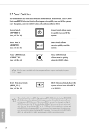
...stability of the BIOS files to the primary BIOS to "B", then the backup BIOS will work on the primary BIOS. 2.7 Smart Switches The motherboard has four smart switches: Power Switch, Reset Switch, Clear CMOS Switch and BIOS Selection Switch, allowing users to quickly turn on/off the... system. BIOS Selection Switch (BIOS_SEL1) (see p.1, No. 20) Power Switch allows users to update the backup BIOS manually. This motherboard has two BIOS chips, a primary BIOS (BIOS_A) and a backup BIOS (BIOS_ B), which BIOS is workable only when you power off your system. ...
...stability of the BIOS files to the primary BIOS to "B", then the backup BIOS will work on the primary BIOS. 2.7 Smart Switches The motherboard has four smart switches: Power Switch, Reset Switch, Clear CMOS Switch and BIOS Selection Switch, allowing users to quickly turn on/off the... system. BIOS Selection Switch (BIOS_SEL1) (see p.1, No. 20) Power Switch allows users to update the backup BIOS manually. This motherboard has two BIOS chips, a primary BIOS (BIOS_A) and a backup BIOS (BIOS_ B), which BIOS is workable only when you power off your system. ...
Quick Installation Guide
Page 32
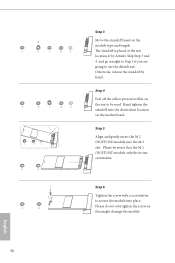
.... Hand tighten the standoff into the M.2 slot. Otherwise, release the standoff by default. Please be used. E D C B A E D C B A C B A E D C B A E D NUT2 NUT1 Step 3 Move the standoff based on the motherboard. Skip Step 3 and 4 and go straight to Step 5 if you are going to use the default nut.
.... Hand tighten the standoff into the M.2 slot. Otherwise, release the standoff by default. Please be used. E D C B A E D C B A C B A E D C B A E D NUT2 NUT1 Step 3 Move the standoff based on the motherboard. Skip Step 3 and 4 and go straight to Step 5 if you are going to use the default nut.
Quick Installation Guide
Page 34
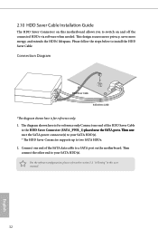
... energy, and extends the HDDs' lifespans. Connect one end of the SATA data cable to a SATA port on the motherboard. For the software configuration, please refer to the section 3.2 "A-Tuning" in this motherboard allows you to two SATA HDDs. 2. Connection Diagram 1 HDD Saver Cable 2 SATA Data Cable *The diagram shown here is...
... energy, and extends the HDDs' lifespans. Connect one end of the SATA data cable to a SATA port on the motherboard. For the software configuration, please refer to the section 3.2 "A-Tuning" in this motherboard allows you to two SATA HDDs. 2. Connection Diagram 1 HDD Saver Cable 2 SATA Data Cable *The diagram shown here is...


