
Intel Smart Response Installation Guide
Page 1
... Icon tray, lower right-hand corner of the screen. 4. For the new version RST driver, please check our website for the latest information: http://www.asrock.com * Before you use Enhanced or Maximized Mode. 6. You can find the UI setup instruction and the step by double-clicking RST Storage icon in... step instructions below. For all required drivers, including RST storage driver version 10.5 or later. 2. UI setup instruction: 1. Intel Smart Response Technology Installation Guide This motherboard supports Intel Smart Response Technology.
... Icon tray, lower right-hand corner of the screen. 4. For the new version RST driver, please check our website for the latest information: http://www.asrock.com * Before you use Enhanced or Maximized Mode. 6. You can find the UI setup instruction and the step by double-clicking RST Storage icon in... step instructions below. For all required drivers, including RST storage driver version 10.5 or later. 2. UI setup instruction: 1. Intel Smart Response Technology Installation Guide This motherboard supports Intel Smart Response Technology.
User Manual
Page 2
... please follow the related regulations in this documentation may or may apply, see www.dtsc.ca.gov/hazardouswaste/ perchlorate" ASRock Website: http://www.asrock.com All rights reserved. With respect to the following two conditions: (1) this device may not cause harmful interference, and... (2) this documentation may cause undesired operation. Operation is subject to the contents of this motherboard contains Perchlorate, a toxic substance ...
... please follow the related regulations in this documentation may or may apply, see www.dtsc.ca.gov/hazardouswaste/ perchlorate" ASRock Website: http://www.asrock.com All rights reserved. With respect to the following two conditions: (1) this device may not cause harmful interference, and... (2) this documentation may cause undesired operation. Operation is subject to the contents of this motherboard contains Perchlorate, a toxic substance ...
User Manual
Page 4
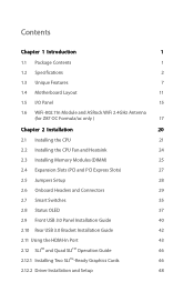
Contents Chapter 1 Introduction 1 1.1 Package Contents 1 1.2 Specifications 2 1.3 Unique Features 7 1.4 Motherboard Layout 11 1.5 I/O Panel 15 1.6 WiFi-802.11n Module and ASRock WiFi 2.4GHz Antenna (for Z87 OC Formula/ac only ) 17 Chapter 2 Installation 20 2.1 Installing the CPU 21 2.2 Installing the CPU Fan and Heatsink 24 2.3 Installing Memory Modules (DIMM) 25 2.4 Expansion Slots (PCI and ...
Contents Chapter 1 Introduction 1 1.1 Package Contents 1 1.2 Specifications 2 1.3 Unique Features 7 1.4 Motherboard Layout 11 1.5 I/O Panel 15 1.6 WiFi-802.11n Module and ASRock WiFi 2.4GHz Antenna (for Z87 OC Formula/ac only ) 17 Chapter 2 Installation 20 2.1 Installing the CPU 21 2.2 Installing the CPU Fan and Heatsink 24 2.3 Installing Memory Modules (DIMM) 25 2.4 Expansion Slots (PCI and ...
User Manual
Page 7
... without notice. If you require technical support related to change without further notice. ASRock website http://www.asrock.com. 1.1 Package Contents • ASRock Z87 OC Formula/ac / Z87 OC Formula Motherboard (EATX Form Factor) • ASRock Z87 OC Formula/ac / Z87 OC Formula Quick Installation Guide • ASRock Z87 OC Formula/ac / Z87 OC Formula Support CD • 10 x Serial ATA (SATA) Data Cables (Optional) • 2 x SATA 1 to quality and endurance. Chapter 3 contains the operation guide of...
... without notice. If you require technical support related to change without further notice. ASRock website http://www.asrock.com. 1.1 Package Contents • ASRock Z87 OC Formula/ac / Z87 OC Formula Motherboard (EATX Form Factor) • ASRock Z87 OC Formula/ac / Z87 OC Formula Quick Installation Guide • ASRock Z87 OC Formula/ac / Z87 OC Formula Support CD • 10 x Serial ATA (SATA) Data Cables (Optional) • 2 x SATA 1 to quality and endurance. Chapter 3 contains the operation guide of...
User Manual
Page 14
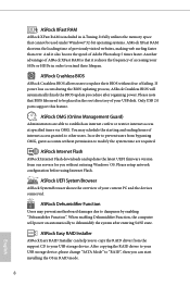
... entering S4/S5 state. Please note that BIOS files need to be used under Windows® 32-bit operating systems. ASRock XFast RAM shortens the loading time of previously visited websites, making web surfing faster than ever. Please setup network configuration before using...disk. Only USB 2.0 ports support this feature. ASRock Easy RAID Installer ASRock Easy RAID Installer can start installing the OS in RAID mode. 8 English You may prevent motherboard damages due to dampness by enabling "Dehumidifier Function". ASRock XFast RAM ASRock XFast RAM is that it also boosts the speed...
... entering S4/S5 state. Please note that BIOS files need to be used under Windows® 32-bit operating systems. ASRock XFast RAM shortens the loading time of previously visited websites, making web surfing faster than ever. Please setup network configuration before using...disk. Only USB 2.0 ports support this feature. ASRock Easy RAID Installer ASRock Easy RAID Installer can start installing the OS in RAID mode. 8 English You may prevent motherboard damages due to dampness by enabling "Dehumidifier Function". ASRock XFast RAM ASRock XFast RAM is that it also boosts the speed...
User Manual
Page 15
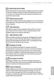
...Windows® OS and your changes will automatically detect your CPU and offer you ever wondered how the global OC champion overclocks his motherboards? No more amusment. ASRock Restart to UEFI allows users to enter the UEFI automatically when turning on entering into the UEFI or restarting...Have a taste of subtle DRAM settings for overclocking this function, the PC will completely change your user experience and behavior. Z87 OC Formula/ac / Z87 OC Formula ASRock Easy Driver Installer For users that don't have to waste time on the PC. The lightning boot up experience. The ...
...Windows® OS and your changes will automatically detect your CPU and offer you ever wondered how the global OC champion overclocks his motherboards? No more amusment. ASRock Restart to UEFI allows users to enter the UEFI automatically when turning on entering into the UEFI or restarting...Have a taste of subtle DRAM settings for overclocking this function, the PC will completely change your user experience and behavior. Z87 OC Formula/ac / Z87 OC Formula ASRock Easy Driver Installer For users that don't have to waste time on the PC. The lightning boot up experience. The ...
User Manual
Page 16
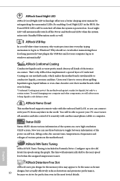
...your computer log in Formula Drive. Good night LED will be switched off when the system is included in to toggle between information of the power on self test, debug codes, the current time, temperatures, frequencies and voltages of various points on the motherboard. ASRock USB Key In a... world where time is met. English ASRock Distortion-Free Slot ASRock's new pin design for perfection even in the world. The fans will be the same as ...
...your computer log in Formula Drive. Good night LED will be switched off when the system is included in to toggle between information of the power on self test, debug codes, the current time, temperatures, frequencies and voltages of various points on the motherboard. ASRock USB Key In a... world where time is met. English ASRock Distortion-Free Slot ASRock's new pin design for perfection even in the world. The fans will be the same as ...
User Manual
Page 17
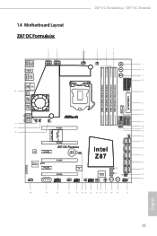
Z87 OC Formula/ac / Z87 OC Formula 1.4 Motherboard Layout Z87 OC Formula/ac 1 2 3 4 5 6 HDMI2 USB 3.0 T: USB0 B: USB1 HDMI1 USB 3.0 T: USB2 Top: RJ-45 B: USB3 44 USB 2.0 T: USB0 B: USB1 PS2 Keyboard /Mouse ATX12V1 ATX12V3 CPU_FAN1 CPU_FAN2 + 7 -... ON ON USB3_12 USB3_10_11 USB3_8_9 LN2MODE1 CHA_FAN3 12 13 14 15 16 17 18 19 WiFi-802.11n Module MINI_PCIE1 20 PCIE2 Z87 OC Formula Intel 21 LAN PCIE3 CMOS CLRCMOS1 Battery 1 Z87 22 Purity RoHS SoundTM PCIE5 PCIE4 HD_AUDIO1 1 SLI/XFIRE_PWR1 PCIE6 COM1 1 Super I/O CHA_FAN1 USB4_5 1 CHA_FAN2 USB2_3 1 Status...
Z87 OC Formula/ac / Z87 OC Formula 1.4 Motherboard Layout Z87 OC Formula/ac 1 2 3 4 5 6 HDMI2 USB 3.0 T: USB0 B: USB1 HDMI1 USB 3.0 T: USB2 Top: RJ-45 B: USB3 44 USB 2.0 T: USB0 B: USB1 PS2 Keyboard /Mouse ATX12V1 ATX12V3 CPU_FAN1 CPU_FAN2 + 7 -... ON ON USB3_12 USB3_10_11 USB3_8_9 LN2MODE1 CHA_FAN3 12 13 14 15 16 17 18 19 WiFi-802.11n Module MINI_PCIE1 20 PCIE2 Z87 OC Formula Intel 21 LAN PCIE3 CMOS CLRCMOS1 Battery 1 Z87 22 Purity RoHS SoundTM PCIE5 PCIE4 HD_AUDIO1 1 SLI/XFIRE_PWR1 PCIE6 COM1 1 Super I/O CHA_FAN1 USB4_5 1 CHA_FAN2 USB2_3 1 Status...

User Manual
Page 23
....0. Bluetooth v4.0 standard features Smart Ready technology that offers support for PCs. ASRock WiFi 2.4GHz Antenna 17 English Z87 OC Formula/ac / Z87 OC Formula 1.6 WiFi-802.11n Module and ASRock WiFi 2.4GHz Antenna (for Z87 OC Formula/ac only ) WiFi + BT Module This motherboard comes with an exclusive WiFi 802.11 a/b/g/n/ac + BT v4.0 module that adds a whole new class of functionality into the...
....0. Bluetooth v4.0 standard features Smart Ready technology that offers support for PCs. ASRock WiFi 2.4GHz Antenna 17 English Z87 OC Formula/ac / Z87 OC Formula 1.6 WiFi-802.11n Module and ASRock WiFi 2.4GHz Antenna (for Z87 OC Formula/ac only ) WiFi + BT Module This motherboard comes with an exclusive WiFi 802.11 a/b/g/n/ac + BT v4.0 module that adds a whole new class of functionality into the...
User Manual
Page 24
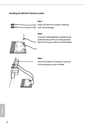
Then attach the SMA Wi-Fi Antenna Cables to the antenna ports on the motherboard's mini-PCIe slot. Step 2 Locate the WiFi Module that come with the package. Step3 Insert the RP-SMA Wi-Fi Antenna Connectors to the WiFi Module. Installing the SMA Wi-Fi Antenna Cables Step 1 Prepare the SMA Wi-Fi Antenna Cables that is installed on the I/O shield 18 English
Then attach the SMA Wi-Fi Antenna Cables to the antenna ports on the motherboard's mini-PCIe slot. Step 2 Locate the WiFi Module that come with the package. Step3 Insert the RP-SMA Wi-Fi Antenna Connectors to the WiFi Module. Installing the SMA Wi-Fi Antenna Cables Step 1 Prepare the SMA Wi-Fi Antenna Cables that is installed on the I/O shield 18 English
User Manual
Page 26
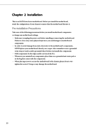
...Chapter 2 Installation This is an EATX form factor motherboard. Before you uninstall any motherboard settings. • Make sure to ensure that comes with the components. • When placing screws to secure the motherboard to you install motherboard components or change any components, place them on ... use a grounded wrist strap or touch a safety grounded object before you and damages to motherboard components. • In order to avoid damage from static electricity to the motherboard's components, NEVER place your chassis to unplug the power cord before installing or removing the...
...Chapter 2 Installation This is an EATX form factor motherboard. Before you uninstall any motherboard settings. • Make sure to ensure that comes with the components. • When placing screws to secure the motherboard to you install motherboard components or change any components, place them on ... use a grounded wrist strap or touch a safety grounded object before you and damages to motherboard components. • In order to avoid damage from static electricity to the motherboard's components, NEVER place your chassis to unplug the power cord before installing or removing the...
User Manual
Page 29
Z87 OC Formula/ac / Z87 OC Formula Please save and replace the cover if the processor is removed. The cover must be placed if you wish to return the motherboard for after service. 23 English
Z87 OC Formula/ac / Z87 OC Formula Please save and replace the cover if the processor is removed. The cover must be placed if you wish to return the motherboard for after service. 23 English
User Manual
Page 31
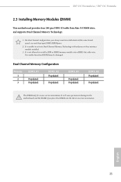
...the DIMM if you always need to install a DDR or DDR2 memory module into the slot at incorrect orientation. Z87 OC Formula/ac / Z87 OC Formula 2.3 Installing Memory Modules (DIMM) This motherboard provides four 240-pin DDR3 (Double Data Rate 3) DIMM slots, and supports Dual Channel Memory Technology. 1. It... is not allowed to install identical (the same brand, speed, size and chip-type) DDR3 DIMM pairs. 2. otherwise, this motherboard and DIMM may be damaged. For dual channel configuration, you force the DIMM into a DDR3 slot; Dual Channel Memory Configuration Priority 1 2 ...
...the DIMM if you always need to install a DDR or DDR2 memory module into the slot at incorrect orientation. Z87 OC Formula/ac / Z87 OC Formula 2.3 Installing Memory Modules (DIMM) This motherboard provides four 240-pin DDR3 (Double Data Rate 3) DIMM slots, and supports Dual Channel Memory Technology. 1. It... is not allowed to install identical (the same brand, speed, size and chip-type) DDR3 DIMM pairs. 2. otherwise, this motherboard and DIMM may be damaged. For dual channel configuration, you force the DIMM into a DDR3 slot; Dual Channel Memory Configuration Priority 1 2 ...
User Manual
Page 33
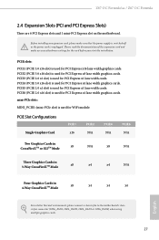
...expansion card, please make necessary hardware settings for PCI Express x4 lane width graphics cards. Z87 OC Formula/ac / Z87 OC Formula 2.4 Expansion Slots (PCI and PCI Express Slots) There are 6 PCI Express slots and 1 mini-PCI Express slot on the motherboard. PCIE slots: PCIE1 (PCIE 3.0 x16 slot) is used for PCI Express x4 ...Four Graphics Cards in 4-Way CrossFireXTM Mode x8 x4 x4 x4 English For a better thermal environment, please connect a chassis fan to the motherboard's chassis fan connector (CHA_FAN1, CHA_FAN2, CHA_FAN3 or CHA_FAN4) when using multiple graphics cards. 27
...expansion card, please make necessary hardware settings for PCI Express x4 lane width graphics cards. Z87 OC Formula/ac / Z87 OC Formula 2.4 Expansion Slots (PCI and PCI Express Slots) There are 6 PCI Express slots and 1 mini-PCI Express slot on the motherboard. PCIE slots: PCIE1 (PCIE 3.0 x16 slot) is used for PCI Express x4 ...Four Graphics Cards in 4-Way CrossFireXTM Mode x8 x4 x4 x4 English For a better thermal environment, please connect a chassis fan to the motherboard's chassis fan connector (CHA_FAN1, CHA_FAN2, CHA_FAN3 or CHA_FAN4) when using multiple graphics cards. 27
User Manual
Page 35
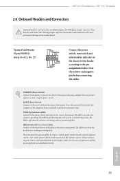
...the system is operating. The LED is in S4 sleep state or powered off (S5). When connecting your system using the power switch. Z87 OC Formula/ac / Z87 OC Formula 2.6 Onboard Headers and Connectors Onboard headers and connectors are matched correctly. The LED keeps blinking when the system is on the chassis front panel...caps over these headers and connectors. Press the reset switch to restart the computer if the computer freezes and fails to the motherboard. English 29 The front panel design may configure the way to turn off when the system is reading or writing data.
...the system is operating. The LED is in S4 sleep state or powered off (S5). When connecting your system using the power switch. Z87 OC Formula/ac / Z87 OC Formula 2.6 Onboard Headers and Connectors Onboard headers and connectors are matched correctly. The LED keeps blinking when the system is on the chassis front panel...caps over these headers and connectors. Press the reset switch to restart the computer if the computer freezes and fails to the motherboard. English 29 The front panel design may configure the way to turn off when the system is reading or writing data.
User Manual
Page 36
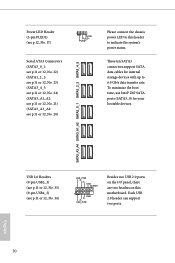
To minimize the boot time, use Intel® Z87 SATA ports (SATA3_0) for internal storage devices with up to indicate the system's power status. PLED+ PLED+ Serial ATA3 Connectors (SATA3_0_1: see p.11 or 12, ... devices. SATA3_A3_A4 SATA3_A1_A2 SATA3_0_1 SATA3_2_3 SATA3_4_5 Power LED Header (3-pin PLED1) (see p.11 or 12, No. 20) Please connect the chassis power LED to this motherboard. USB 2.0 Headers (9-pin USB2_3) (see p.11 or 12, No. 33) (9-pin USB4_5) (see p.11 or 12, No. 36) USB_PWR PP+ GND DUMMY 1 GND P+ PUSB_PWR Besides...
To minimize the boot time, use Intel® Z87 SATA ports (SATA3_0) for internal storage devices with up to indicate the system's power status. PLED+ PLED+ Serial ATA3 Connectors (SATA3_0_1: see p.11 or 12, ... devices. SATA3_A3_A4 SATA3_A1_A2 SATA3_0_1 SATA3_2_3 SATA3_4_5 Power LED Header (3-pin PLED1) (see p.11 or 12, No. 20) Please connect the chassis power LED to this motherboard. USB 2.0 Headers (9-pin USB2_3) (see p.11 or 12, No. 33) (9-pin USB4_5) (see p.11 or 12, No. 36) USB_PWR PP+ GND DUMMY 1 GND P+ PUSB_PWR Besides...
User Manual
Page 37
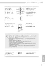
... need to the "FrontMic" Tab in our manual and chassis manual to OUT2_L. B. To activate the front mic, go to connect them for the AC'97 audio panel. Z87 OC Formula/ac / Z87 OC Formula USB 3.0 Headers (19-pin USB3_8_9) (see p.11 or 12, No. 15) (19-pin USB3_10_11) (see p.11 or 12, No. 16...Audio Header (9-pin HD_AUDIO1) (see p.11 or 12, No. 25) DUMMY SPEAKER 1 +5V DUMMY Please connect the chassis speaker to this motherboard. If you use an AC'97 audio panel, please install it to Ground (GND). C. E. Each USB 3.0 header can support two ports. High Definition Audio supports ...
... need to the "FrontMic" Tab in our manual and chassis manual to OUT2_L. B. To activate the front mic, go to connect them for the AC'97 audio panel. Z87 OC Formula/ac / Z87 OC Formula USB 3.0 Headers (19-pin USB3_8_9) (see p.11 or 12, No. 15) (19-pin USB3_10_11) (see p.11 or 12, No. 16...Audio Header (9-pin HD_AUDIO1) (see p.11 or 12, No. 25) DUMMY SPEAKER 1 +5V DUMMY Please connect the chassis speaker to this motherboard. If you use an AC'97 audio panel, please install it to Ground (GND). C. E. Each USB 3.0 header can support two ports. High Definition Audio supports ...

User Manual
Page 38
... +12V MOS_FAN_SPEED CPU Fan Connectors (4-pin CPU_FAN1) (see p.11 or 12, No. 3) (3-pin CPU_FAN2) (see p.11 or 12, No. 12) 32 12 24 1 13 This motherboard provides a 24-pin ATX power connector. ATX Power Connector (24-pin ATXPWR1) (see p.11 or 12, No. 4) 4 3 21 GN D + 12V CPU_ FAN_SPEED FAN_SPEED_CONTROL GND +12V...
... +12V MOS_FAN_SPEED CPU Fan Connectors (4-pin CPU_FAN1) (see p.11 or 12, No. 3) (3-pin CPU_FAN2) (see p.11 or 12, No. 12) 32 12 24 1 13 This motherboard provides a 24-pin ATX power connector. ATX Power Connector (24-pin ATXPWR1) (see p.11 or 12, No. 4) 4 3 21 GN D + 12V CPU_ FAN_SPEED FAN_SPEED_CONTROL GND +12V...
User Manual
Page 39
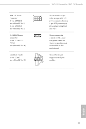
... DDCD#1 Please connect this connector with a hard disk power connector when two graphics cards are installed on this motherboard. This COM1 header supports a serial port module. vides an 8-pin ATX 12V 4 1 power connector. Z87 OC Formula/ac / Z87 OC Formula ATX 12V Power Connector (8-pin ATX12V1) (see p.11 or 12, No. 1) (8-pin ATX12V3) (see p.11 or 12, No...
... DDCD#1 Please connect this connector with a hard disk power connector when two graphics cards are installed on this motherboard. This COM1 header supports a serial port module. vides an 8-pin ATX 12V 4 1 power connector. Z87 OC Formula/ac / Z87 OC Formula ATX 12V Power Connector (8-pin ATX12V1) (see p.11 or 12, No. 1) (8-pin ATX12V3) (see p.11 or 12, No...

User Manual
Page 41
... 12, No. 29) Reset Reset Switch allows users to quickly reset the system. We are not responsible for possible damage caused by overclocking. Z87 OC Formula/ac / Z87 OC Formula 2.7 Smart Switches The motherboard has three smart switches: Power Switch, Reset Switch and Clear CMOS Switch, allowing users to quickly turn on/off the system. This function is...
... 12, No. 29) Reset Reset Switch allows users to quickly reset the system. We are not responsible for possible damage caused by overclocking. Z87 OC Formula/ac / Z87 OC Formula 2.7 Smart Switches The motherboard has three smart switches: Power Switch, Reset Switch and Clear CMOS Switch, allowing users to quickly turn on/off the system. This function is...


