
Intel Smart Response Installation Guide
Page 1
...SATA Mode" to a RAID mode system, then install all performance testing, chose "Maximized" mode. 7. Intel Smart Response Technology Installation Guide This motherboard supports Intel Smart Response Technology. Once open RST GUI from either Start Menu or by step instructions below. For the new version RST driver, ...please check our website for the latest information: http://www.asrock.com * Before you use Enhanced or Maximized Mode. 6. Boot system to build RAID 0 or RAID 1 in Icon tray, lower right-...
...SATA Mode" to a RAID mode system, then install all performance testing, chose "Maximized" mode. 7. Intel Smart Response Technology Installation Guide This motherboard supports Intel Smart Response Technology. Once open RST GUI from either Start Menu or by step instructions below. For the new version RST driver, ...please check our website for the latest information: http://www.asrock.com * Before you use Enhanced or Maximized Mode. 6. Boot system to build RAID 0 or RAID 1 in Icon tray, lower right-...
User Manual
Page 2
...and should not be constructed as a commitment by the purchaser for a particular purpose. Copyright Notice: No part of documentation by ASRock. Operation is subject to infringe. Disclaimer: Specifications and information contained in any form or by the California Legislature. CALIFORNIA, USA ONLY... The Lithium battery adopted on this motherboard contains Perchlorate, a toxic substance controlled in this device must accept any errors or omissions that may apply, see www.dtsc....
...and should not be constructed as a commitment by the purchaser for a particular purpose. Copyright Notice: No part of documentation by ASRock. Operation is subject to infringe. Disclaimer: Specifications and information contained in any form or by the California Legislature. CALIFORNIA, USA ONLY... The Lithium battery adopted on this motherboard contains Perchlorate, a toxic substance controlled in this device must accept any errors or omissions that may apply, see www.dtsc....
User Manual
Page 4
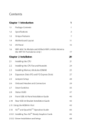
Contents Chapter 1 Introduction 1 1.1 Package Contents 1 1.2 Specifications 2 1.3 Unique Features 7 1.4 Motherboard Layout 11 1.5 I/O Panel 15 1.6 WiFi-802.11n Module and ASRock WiFi 2.4GHz Antenna (for Z87 OC Formula/ac only ) 17 Chapter 2 Installation 20 2.1 Installing the CPU 21 2.2 Installing the CPU Fan and Heatsink 24 2.3 Installing Memory Modules (DIMM) 25 2.4 Expansion Slots (PCI and ...
Contents Chapter 1 Introduction 1 1.1 Package Contents 1 1.2 Specifications 2 1.3 Unique Features 7 1.4 Motherboard Layout 11 1.5 I/O Panel 15 1.6 WiFi-802.11n Module and ASRock WiFi 2.4GHz Antenna (for Z87 OC Formula/ac only ) 17 Chapter 2 Installation 20 2.1 Installing the CPU 21 2.2 Installing the CPU Fan and Heatsink 24 2.3 Installing Memory Modules (DIMM) 25 2.4 Expansion Slots (PCI and ...
User Manual
Page 7
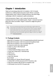
... related to this documentation will be updated, the content of this motherboard, please visit our website for specific information about the model you for Z87 OC Formula only) 1 English ASRock website http://www.asrock.com. 1.1 Package Contents • ASRock Z87 OC Formula/ac / Z87 OC Formula Motherboard (EATX Form Factor) • ASRock Z87 OC Formula/ac / Z87 OC Formula Quick Installation Guide • ASRock Z87 OC Formula/ac / Z87 OC Formula Support CD • 10 x Serial ATA (SATA) Data Cables (Optional...
... related to this documentation will be updated, the content of this motherboard, please visit our website for specific information about the model you for Z87 OC Formula only) 1 English ASRock website http://www.asrock.com. 1.1 Package Contents • ASRock Z87 OC Formula/ac / Z87 OC Formula Motherboard (EATX Form Factor) • ASRock Z87 OC Formula/ac / Z87 OC Formula Quick Installation Guide • ASRock Z87 OC Formula/ac / Z87 OC Formula Support CD • 10 x Serial ATA (SATA) Data Cables (Optional...
User Manual
Page 14
... RAM is included in A-Tuning. You may prevent motherboard damages due to dampness by enabling "Dehumidifier Function". Please setup network configuration before using Internet Flash. ASRock UEFI System Browser ASRock System Browser shows the overview of internet access granted to copy the RAID driver ... and the devices connected. And it reduces the frequency of previously visited websites, making web surfing faster than ever. ASRock Internet Flash ASRock Internet Flash downloads and updates the latest UEFI firmware version from the support CD to extend their BIOS without fear of...
... RAM is included in A-Tuning. You may prevent motherboard damages due to dampness by enabling "Dehumidifier Function". Please setup network configuration before using Internet Flash. ASRock UEFI System Browser ASRock System Browser shows the overview of internet access granted to copy the RAID driver ... and the devices connected. And it reduces the frequency of previously visited websites, making web surfing faster than ever. ASRock Internet Flash ASRock Internet Flash downloads and updates the latest UEFI firmware version from the support CD to extend their BIOS without fear of...
User Manual
Page 15
... Have you restart. The speedy boot will take effect immediately. 9 English By enabling this motherboard instantly. Z87 OC Formula/ac / Z87 OC Formula ASRock Easy Driver Installer For users that don't have to pursuit extremes. ASRock Interactive UEFI ASRock Interactive UEFI is a blend of voltage fine tuning options in the UEFI that installs the LAN driver to enter the UEFI automatically...
... Have you restart. The speedy boot will take effect immediately. 9 English By enabling this motherboard instantly. Z87 OC Formula/ac / Z87 OC Formula ASRock Easy Driver Installer For users that don't have to pursuit extremes. ASRock Interactive UEFI ASRock Interactive UEFI is a blend of voltage fine tuning options in the UEFI that installs the LAN driver to enter the UEFI automatically...
User Manual
Page 16
... much destroy all kinds of the system on our motherboards, which makes the motherboards invulnerable to keep liquids a safe distance away. Status OLED Status OLED shows various information of electronics on the motherboard. ASRock FAN-Tastic Tuning ASRock FAN-Tastic Tuning is money, why waste precious time... enabling Good Night LED in the world. Why should we strive for the memory slots may protect the motherboard against conductive liquids, but only to windows automatically! English ASRock Distortion-Free Slot ASRock's new pin design for perfection even in Formula Drive.
... much destroy all kinds of the system on our motherboards, which makes the motherboards invulnerable to keep liquids a safe distance away. Status OLED Status OLED shows various information of electronics on the motherboard. ASRock FAN-Tastic Tuning ASRock FAN-Tastic Tuning is money, why waste precious time... enabling Good Night LED in the world. Why should we strive for the memory slots may protect the motherboard against conductive liquids, but only to windows automatically! English ASRock Distortion-Free Slot ASRock's new pin design for perfection even in Formula Drive.
User Manual
Page 17
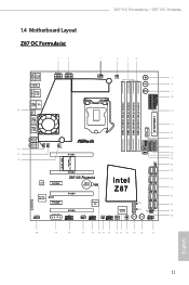
Z87 OC Formula/ac / Z87 OC Formula 1.4 Motherboard Layout Z87 OC Formula/ac 1 2 3 4 5 6 HDMI2 USB 3.0 T: USB0 B: USB1 HDMI1 USB 3.0 T: USB2 Top: RJ-45 B: USB3 44 USB 2.0 T: USB0 B: USB1 PS2 Keyboard /Mouse ATX12V1 ATX12V3 CPU_FAN1 CPU_FAN2 + 7 -... ON ON USB3_12 USB3_10_11 USB3_8_9 LN2MODE1 CHA_FAN3 12 13 14 15 16 17 18 19 WiFi-802.11n Module MINI_PCIE1 20 PCIE2 Z87 OC Formula Intel 21 LAN PCIE3 CMOS CLRCMOS1 Battery 1 Z87 22 Purity RoHS SoundTM PCIE5 PCIE4 HD_AUDIO1 1 SLI/XFIRE_PWR1 PCIE6 COM1 1 Super I/O CHA_FAN1 USB4_5 1 CHA_FAN2 USB2_3 1 Status...
Z87 OC Formula/ac / Z87 OC Formula 1.4 Motherboard Layout Z87 OC Formula/ac 1 2 3 4 5 6 HDMI2 USB 3.0 T: USB0 B: USB1 HDMI1 USB 3.0 T: USB2 Top: RJ-45 B: USB3 44 USB 2.0 T: USB0 B: USB1 PS2 Keyboard /Mouse ATX12V1 ATX12V3 CPU_FAN1 CPU_FAN2 + 7 -... ON ON USB3_12 USB3_10_11 USB3_8_9 LN2MODE1 CHA_FAN3 12 13 14 15 16 17 18 19 WiFi-802.11n Module MINI_PCIE1 20 PCIE2 Z87 OC Formula Intel 21 LAN PCIE3 CMOS CLRCMOS1 Battery 1 Z87 22 Purity RoHS SoundTM PCIE5 PCIE4 HD_AUDIO1 1 SLI/XFIRE_PWR1 PCIE6 COM1 1 Super I/O CHA_FAN1 USB4_5 1 CHA_FAN2 USB2_3 1 Status...

User Manual
Page 23
... v4.0 standard features Smart Ready technology that offers support for PCs. Z87 OC Formula/ac / Z87 OC Formula 1.6 WiFi-802.11n Module and ASRock WiFi 2.4GHz Antenna (for Z87 OC Formula/ac only ) WiFi + BT Module This motherboard comes with an exclusive WiFi 802.11 a/b/g/n/ac + BT v4.0 module that adds a whole new class of functionality...WiFi + BT module is an easy-to-use wireless local area network (WLAN) adapter to support WiFi + BT. ASRock WiFi 2.4GHz Antenna 17 English BT 4.0 also includes Low Energy Technology and ensures extraordinary low power consumption for WiFi 802.11...
... v4.0 standard features Smart Ready technology that offers support for PCs. Z87 OC Formula/ac / Z87 OC Formula 1.6 WiFi-802.11n Module and ASRock WiFi 2.4GHz Antenna (for Z87 OC Formula/ac only ) WiFi + BT Module This motherboard comes with an exclusive WiFi 802.11 a/b/g/n/ac + BT v4.0 module that adds a whole new class of functionality...WiFi + BT module is an easy-to-use wireless local area network (WLAN) adapter to support WiFi + BT. ASRock WiFi 2.4GHz Antenna 17 English BT 4.0 also includes Low Energy Technology and ensures extraordinary low power consumption for WiFi 802.11...
User Manual
Page 24
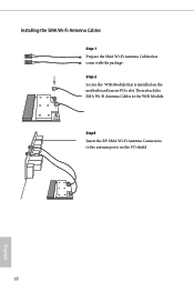
Then attach the SMA Wi-Fi Antenna Cables to the antenna ports on the motherboard's mini-PCIe slot. Step3 Insert the RP-SMA Wi-Fi Antenna Connectors to the WiFi Module. Step 2 Locate the WiFi Module that come with the package. Installing the SMA Wi-Fi Antenna Cables Step 1 Prepare the SMA Wi-Fi Antenna Cables that is installed on the I/O shield 18 English
Then attach the SMA Wi-Fi Antenna Cables to the antenna ports on the motherboard's mini-PCIe slot. Step3 Insert the RP-SMA Wi-Fi Antenna Connectors to the WiFi Module. Step 2 Locate the WiFi Module that come with the package. Installing the SMA Wi-Fi Antenna Cables Step 1 Prepare the SMA Wi-Fi Antenna Cables that is installed on the I/O shield 18 English
User Manual
Page 26
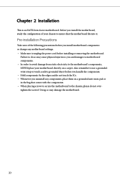
... configuration of the following precautions before installing or removing the motherboard. Chapter 2 Installation This is an EATX form factor motherboard. Doing so may cause physical injuries to you and damages to motherboard components. • In order to avoid damage from static electricity to the motherboard's components, NEVER place your chassis to ensure that comes...
... configuration of the following precautions before installing or removing the motherboard. Chapter 2 Installation This is an EATX form factor motherboard. Doing so may cause physical injuries to you and damages to motherboard components. • In order to avoid damage from static electricity to the motherboard's components, NEVER place your chassis to ensure that comes...
User Manual
Page 29
Z87 OC Formula/ac / Z87 OC Formula Please save and replace the cover if the processor is removed. The cover must be placed if you wish to return the motherboard for after service. 23 English
Z87 OC Formula/ac / Z87 OC Formula Please save and replace the cover if the processor is removed. The cover must be placed if you wish to return the motherboard for after service. 23 English
User Manual
Page 31
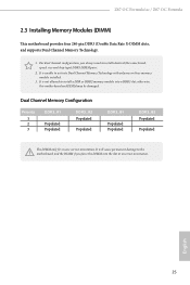
...not allowed to activate Dual Channel Memory Technology with only one correct orientation. otherwise, this motherboard and DIMM may be damaged. English 25 For dual channel configuration, you always need to the motherboard and the DIMM if you force the DIMM into a DDR3 slot; Dual Channel Memory...3. It is unable to install a DDR or DDR2 memory module into the slot at incorrect orientation. Z87 OC Formula/ac / Z87 OC Formula 2.3 Installing Memory Modules (DIMM) This motherboard provides four 240-pin DDR3 (Double Data Rate 3) DIMM slots, and supports Dual Channel Memory Technology. 1.
...not allowed to activate Dual Channel Memory Technology with only one correct orientation. otherwise, this motherboard and DIMM may be damaged. English 25 For dual channel configuration, you always need to the motherboard and the DIMM if you force the DIMM into a DDR3 slot; Dual Channel Memory...3. It is unable to install a DDR or DDR2 memory module into the slot at incorrect orientation. Z87 OC Formula/ac / Z87 OC Formula 2.3 Installing Memory Modules (DIMM) This motherboard provides four 240-pin DDR3 (Double Data Rate 3) DIMM slots, and supports Dual Channel Memory Technology. 1.
User Manual
Page 33
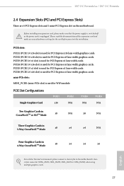
...3.0 x16 slot) is used for PCI Express x4 lane width graphics cards. Z87 OC Formula/ac / Z87 OC Formula 2.4 Expansion Slots (PCI and PCI Express Slots) There are 6 PCI Express slots and 1 mini-PCI Express slot on the motherboard. PCIE6 (PCIE 2.0 x16 slot) is used for PCI Express x16 lane ... Cards in 4-Way CrossFireXTM Mode x8 x4 x4 x4 English For a better thermal environment, please connect a chassis fan to the motherboard's chassis fan connector (CHA_FAN1, CHA_FAN2, CHA_FAN3 or CHA_FAN4) when using multiple graphics cards. 27 Please read the documentation of the ...
...3.0 x16 slot) is used for PCI Express x4 lane width graphics cards. Z87 OC Formula/ac / Z87 OC Formula 2.4 Expansion Slots (PCI and PCI Express Slots) There are 6 PCI Express slots and 1 mini-PCI Express slot on the motherboard. PCIE6 (PCIE 2.0 x16 slot) is used for PCI Express x16 lane ... Cards in 4-Way CrossFireXTM Mode x8 x4 x4 x4 English For a better thermal environment, please connect a chassis fan to the motherboard's chassis fan connector (CHA_FAN1, CHA_FAN2, CHA_FAN3 or CHA_FAN4) when using multiple graphics cards. 27 Please read the documentation of the ...
User Manual
Page 35
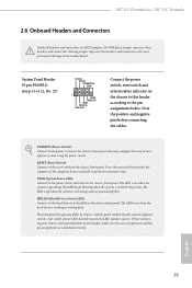
... panel. HDLED (Hard Drive Activity LED): Connect to perform a normal restart. Z87 OC Formula/ac / Z87 OC Formula 2.6 Onboard Headers and Connectors Onboard headers and connectors are matched correctly. Do NOT place jumper caps over the headers and connectors will cause permanent damage to the motherboard. PWRBTN (Power Switch): Connect to the reset switch on when the hard...
... panel. HDLED (Hard Drive Activity LED): Connect to perform a normal restart. Z87 OC Formula/ac / Z87 OC Formula 2.6 Onboard Headers and Connectors Onboard headers and connectors are matched correctly. Do NOT place jumper caps over the headers and connectors will cause permanent damage to the motherboard. PWRBTN (Power Switch): Connect to the reset switch on when the hard...
User Manual
Page 36
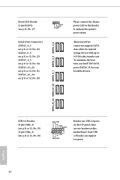
.... 21) (SATA3_A3_A4: see p.11 or 12, No. 20) Please connect the chassis power LED to this motherboard. Each USB 2.0 header can support two ports. 30 English To minimize the boot time, use Intel® Z87 SATA ports (SATA3_0) for internal storage devices with up to indicate the system's power status. USB 2.0 Headers...
.... 21) (SATA3_A3_A4: see p.11 or 12, No. 20) Please connect the chassis power LED to this motherboard. Each USB 2.0 header can support two ports. 30 English To minimize the boot time, use Intel® Z87 SATA ports (SATA3_0) for internal storage devices with up to indicate the system's power status. USB 2.0 Headers...
User Manual
Page 37
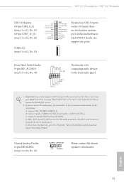
E. Z87 OC Formula/ac / Z87 OC Formula USB 3.0 Headers (19-pin USB3_8_9) (see p.11 or 12, No. 15) (19-pin USB3_10_11) (see p.11 or 12, No. 16) (USB3_12) (see p.11 or 12, No. 25) DUMMY SPEAKER 1 +5V DUMMY Please connect the chassis speaker to this motherboard. Please follow the instructions in the Realtek Control panel and adjust "Recording Volume...
E. Z87 OC Formula/ac / Z87 OC Formula USB 3.0 Headers (19-pin USB3_8_9) (see p.11 or 12, No. 15) (19-pin USB3_10_11) (see p.11 or 12, No. 16) (USB3_12) (see p.11 or 12, No. 25) DUMMY SPEAKER 1 +5V DUMMY Please connect the chassis speaker to this motherboard. Please follow the instructions in the Realtek Control panel and adjust "Recording Volume...

User Manual
Page 38
... Connectors (4-pin CPU_FAN1) (see p.11 or 12, No. 3) (3-pin CPU_FAN2) (see p.11 or 12, No. 4) 4 3 21 GN D + 12V CPU_ FAN_SPEED FAN_SPEED_CONTROL GND +12V CPU_FAN_SPEED This motherboard provides a 4-Pin CPU fan (Quiet Fan) connector. English If you plan to connect a 3-Pin CPU fan, please connect it along Pin 1 and Pin 13. Chassis... connectors and match the black wire to Pin 1-3. ATX Power Connector (24-pin ATXPWR1) (see p.11 or 12, No. 12) 32 12 24 1 13 This motherboard provides a 24-pin ATX power connector.
... Connectors (4-pin CPU_FAN1) (see p.11 or 12, No. 3) (3-pin CPU_FAN2) (see p.11 or 12, No. 4) 4 3 21 GN D + 12V CPU_ FAN_SPEED FAN_SPEED_CONTROL GND +12V CPU_FAN_SPEED This motherboard provides a 4-Pin CPU fan (Quiet Fan) connector. English If you plan to connect a 3-Pin CPU fan, please connect it along Pin 1 and Pin 13. Chassis... connectors and match the black wire to Pin 1-3. ATX Power Connector (24-pin ATXPWR1) (see p.11 or 12, No. 12) 32 12 24 1 13 This motherboard provides a 24-pin ATX power connector.
User Manual
Page 39
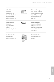
...Z87 OC Formula/ac / Z87 OC Formula ATX 12V Power Connector (8-pin ATX12V1) (see p.11 or 12, No. 1) (8-pin ATX12V3) (see p.11 or 12, No. 2) SLI/XFIRE Power Connector (4-pin SLI/XFIRE_ PWR1) (see p.11 or 12, No. 39) Serial Port Header (9-pin COM1) (see p.11 or 12, No. 38) 8 5 This motherboard... pro- vides an 8-pin ATX 12V 4 1 power connector. RRXD1 DDTR#1 DDSR#1 CCTS#1 1 RRI#1 RRTS#1 GND TTXD1 DDCD#1 Please connect this connector with a hard disk power connector when two graphics cards are installed on this motherboard.
...Z87 OC Formula/ac / Z87 OC Formula ATX 12V Power Connector (8-pin ATX12V1) (see p.11 or 12, No. 1) (8-pin ATX12V3) (see p.11 or 12, No. 2) SLI/XFIRE Power Connector (4-pin SLI/XFIRE_ PWR1) (see p.11 or 12, No. 39) Serial Port Header (9-pin COM1) (see p.11 or 12, No. 38) 8 5 This motherboard... pro- vides an 8-pin ATX 12V 4 1 power connector. RRXD1 DDTR#1 DDSR#1 CCTS#1 1 RRI#1 RRTS#1 GND TTXD1 DDCD#1 Please connect this connector with a hard disk power connector when two graphics cards are installed on this motherboard.

User Manual
Page 41
...) Reset Reset Switch allows users to quickly reset the system. We are not responsible for possible damage caused by overclocking. Z87 OC Formula/ac / Z87 OC Formula 2.7 Smart Switches The motherboard has three smart switches: Power Switch, Reset Switch and Clear CMOS Switch, allowing users to quickly turn on /off the... system, reset the system or clear the CMOS values. Rapid OC Buttons allow users to quickly toogle among Date/ Time, ...
...) Reset Reset Switch allows users to quickly reset the system. We are not responsible for possible damage caused by overclocking. Z87 OC Formula/ac / Z87 OC Formula 2.7 Smart Switches The motherboard has three smart switches: Power Switch, Reset Switch and Clear CMOS Switch, allowing users to quickly turn on /off the... system, reset the system or clear the CMOS values. Rapid OC Buttons allow users to quickly toogle among Date/ Time, ...


