Intel Rapid Storage Guide
Page 13
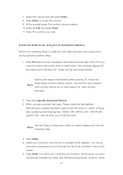
... Enter. 11. Use the Floppy Configuration Utility to create a floppy disk with a screen asking you need to load support for mass storage device(s). 2. Press Enter to create the volume. 9. Setup will happen immediately after pressing F6. Select your exit. At the prompt press Y to confirm your controller from the list of Windows XP* setup (during operating system setup: 1. Nothing will temporarily continue loading drivers. Install the RAID Driver Using the F6 Installation Method Perform the following files...
... Enter. 11. Use the Floppy Configuration Utility to create a floppy disk with a screen asking you need to load support for mass storage device(s). 2. Press Enter to create the volume. 9. Setup will happen immediately after pressing F6. Select your exit. At the prompt press Y to confirm your controller from the list of Windows XP* setup (during operating system setup: 1. Nothing will temporarily continue loading drivers. Install the RAID Driver Using the F6 Installation Method Perform the following files...

Intel Smart Response Installation Guide
Page 1
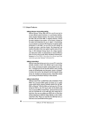
... this point! 3. Intel Smart Response Technology Installation Guide This motherboard supports Intel Smart Response Technology. Complete initial system setup, including installing the OS to desktop, open , click on the "Enable Acceleration" button on the GUI panel. 5. UI setup instruction: 1. Boot system to a RAID mode system, then install all performance testing, chose "Maximized" mode. 7. After clicking OK button, SRT will enable automatically, and the RST GUI will update the new version RST driver in RAID ROM. It is not...
... this point! 3. Intel Smart Response Technology Installation Guide This motherboard supports Intel Smart Response Technology. Complete initial system setup, including installing the OS to desktop, open , click on the "Enable Acceleration" button on the GUI panel. 5. UI setup instruction: 1. Boot system to a RAID mode system, then install all performance testing, chose "Maximized" mode. 7. After clicking OK button, SRT will enable automatically, and the RST GUI will update the new version RST driver in RAID ROM. It is not...

RAID Installation Guide
Page 6
... system. Set "SATA Mode Selection" to set RAID configuration. Please refer to the document in the Support CD, "Guide to SATA Hard Disks Installation and RAID Configuration", which is not supported under Windows® XP / XP 64-bit. Enter BIOS SETUP UTILITY Advanced screen Storage Configuration. Before you start to configure the RAID function, you are allowed to use "Intel Rapid Storage" in the Support CD for RAID con...
... system. Set "SATA Mode Selection" to set RAID configuration. Please refer to the document in the Support CD, "Guide to SATA Hard Disks Installation and RAID Configuration", which is not supported under Windows® XP / XP 64-bit. Enter BIOS SETUP UTILITY Advanced screen Storage Configuration. Before you start to configure the RAID function, you are allowed to use "Intel Rapid Storage" in the Support CD for RAID con...
User Manual
Page 8
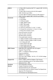
...- Drivers, Utilities, AntiVirus Software (Trial Version), CyberLink MediaEspresso 6.5 Trial, ASRock MAGIX Multimedia Suite - CPU/Chassis Fan Multi-Speed Control 8 CPU Core, IGPU, DRAM, 1.8V PLL, VTT, VCCSA Voltage Multi-adjustment - SLI/XFire power connector - Supports jumperfree - USB3.0 Connector BIOS Feature Support CD Hardware Monitor - 4 x Rear USB 3.0 ports by Intel® Z77, support USB 1.0/2.0/3.0 up to 5Gb/s - 4 x Rear USB 3.0 ports by Etron EJ188, support USB 1.0/2.0/3.0 up to 5Gb/s - 2 x Front USB 3.0 headers by CPU Temperature) - CPU Temperature Sensing - ACPI...
...- Drivers, Utilities, AntiVirus Software (Trial Version), CyberLink MediaEspresso 6.5 Trial, ASRock MAGIX Multimedia Suite - CPU/Chassis Fan Multi-Speed Control 8 CPU Core, IGPU, DRAM, 1.8V PLL, VTT, VCCSA Voltage Multi-adjustment - SLI/XFire power connector - Supports jumperfree - USB3.0 Connector BIOS Feature Support CD Hardware Monitor - 4 x Rear USB 3.0 ports by Intel® Z77, support USB 1.0/2.0/3.0 up to 5Gb/s - 4 x Rear USB 3.0 ports by Etron EJ188, support USB 1.0/2.0/3.0 up to 5Gb/s - 2 x Front USB 3.0 headers by CPU Temperature) - CPU Temperature Sensing - ACPI...
User Manual
Page 13
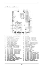
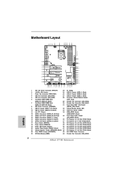
...) 16 SATA2 Connectors (SATA2_4_5, Black) 37 PCI Express 2.0 x1 Slot (PCIE6, Black) 17 Reset Switch (RSTBTN) 38 PCI Express 3.0 x16 Slot (PCIE5, Black) 18 Power Switch (PWRBTN) 39 PCI Express 2.0 x16 Slot (PCIE4, Black) 19 Power LED Header (PLED1) 40 PCI Express 3.0 x16 Slot (PCIE3, Black) 20 System Panel Header (PANEL1, Black) 41 PCI Express 3.0 x16 Slot (PCIE2, Black) 21 Chassis Speaker Header (SPEAKER1, Black) 42 PCI Express 3.0 x16 Slot (PCIE1, Black) 22 Clear CMOS Jumper (CLRCMOS1) 43 SLI / XFIRE Power Connector 23 SPI Flash Memory (64Mb) 44 Chassis Fan Connector (CHA_FAN3...
...) 16 SATA2 Connectors (SATA2_4_5, Black) 37 PCI Express 2.0 x1 Slot (PCIE6, Black) 17 Reset Switch (RSTBTN) 38 PCI Express 3.0 x16 Slot (PCIE5, Black) 18 Power Switch (PWRBTN) 39 PCI Express 2.0 x16 Slot (PCIE4, Black) 19 Power LED Header (PLED1) 40 PCI Express 3.0 x16 Slot (PCIE3, Black) 20 System Panel Header (PANEL1, Black) 41 PCI Express 3.0 x16 Slot (PCIE2, Black) 21 Chassis Speaker Header (SPEAKER1, Black) 42 PCI Express 3.0 x16 Slot (PCIE1, Black) 22 Clear CMOS Jumper (CLRCMOS1) 43 SLI / XFIRE Power Connector 23 SPI Flash Memory (64Mb) 44 Chassis Fan Connector (CHA_FAN3...
User Manual
Page 35
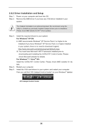
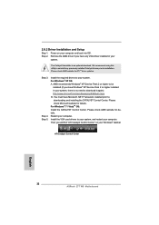
... any previously installed Catalyst drivers prior to be installed (If you have Windows® XP Service Pack 2 or higher installed in your computer and boot into OS. Step 3. Install the VGA card drivers to your Windows® taskbar. 2.8.2 Driver Installation and Setup Step 1. Install the required drivers to your system, and restart your computer. The Catalyst Uninstaller is no need to downloading and installing the CATALYST Control Center. Remove the AMD driver if...
... any previously installed Catalyst drivers prior to be installed (If you have Windows® XP Service Pack 2 or higher installed in your computer and boot into OS. Step 3. Install the VGA card drivers to your Windows® taskbar. 2.8.2 Driver Installation and Setup Step 1. Install the required drivers to your system, and restart your computer. The Catalyst Uninstaller is no need to downloading and installing the CATALYST Control Center. Remove the AMD driver if...
User Manual
Page 50
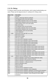
... module specific) Pre-memory South Bridge initialization is started Pre-memory South Bridge initialization (South Bridge module specific) Pre-memory South Bridge initialization (South Bridge module specific) Pre-memory South Bridge initialization (South Bridge module specific) OEM pre-memory initialization codes Memory initialization. Memory presence detection Memory initialization. Application Processor(s) (AP) initialization CPU post-memory initialization. 2.14 Dr. Debug Dr. Debug is used Power on. Boot Strap Processor (BSP) selection CPU post-memory initialization. Status Code...
... module specific) Pre-memory South Bridge initialization is started Pre-memory South Bridge initialization (South Bridge module specific) Pre-memory South Bridge initialization (South Bridge module specific) Pre-memory South Bridge initialization (South Bridge module specific) OEM pre-memory initialization codes Memory initialization. Memory presence detection Memory initialization. Application Processor(s) (AP) initialization CPU post-memory initialization. 2.14 Dr. Debug Dr. Debug is used Power on. Boot Strap Processor (BSP) selection CPU post-memory initialization. Status Code...

User Manual
Page 58
... driver page. Please refer to the document in the Support CD, "Guide to SATA Hard Disks Installation and RAID Configuration", which is located in the Support CD for SATA2_2 to SATA2_5 and SATA3_0 and SATA3_1 ports. STEP 1: Set up to bottom side to install those required drivers. RAID mode is located in the support CD, "Guide to set RAID configuration. Enter UEFI SETUP UTILITY Advanced screen Storage Configuration. STEP 2: Use "RAID Installation Guide" to Intel Rapid Storage", which is not supported under Windows® XP / XP 64-bit...
... driver page. Please refer to the document in the Support CD, "Guide to SATA Hard Disks Installation and RAID Configuration", which is located in the Support CD for SATA2_2 to SATA2_5 and SATA3_0 and SATA3_1 ports. STEP 1: Set up to bottom side to install those required drivers. RAID mode is located in the support CD, "Guide to set RAID configuration. Enter UEFI SETUP UTILITY Advanced screen Storage Configuration. STEP 2: Use "RAID Installation Guide" to Intel Rapid Storage", which is not supported under Windows® XP / XP 64-bit...
User Manual
Page 73
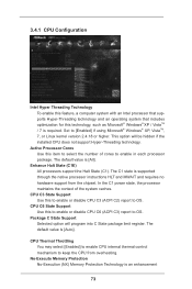
... Support Use this to enable or disable CPU C3 (ACPI C2) report to keep the CPU from the chipset. CPU C3 State Support Use this to enable or disable CPU C6 (ACPI C3) report to [Enabled] if using Microsoft® Windows® XP, VistaTM, 7, or Linux kernel version 2.4.18 or higher. This option will program into C State package limit register. The default value is [Auto]. CPU Thermal Throttling You may select [Enabled] to enable CPU internal thermal control...
... Support Use this to enable or disable CPU C3 (ACPI C2) report to keep the CPU from the chipset. CPU C3 State Support Use this to enable or disable CPU C6 (ACPI C3) report to [Enabled] if using Microsoft® Windows® XP, VistaTM, 7, or Linux kernel version 2.4.18 or higher. This option will program into C State package limit register. The default value is [Auto]. CPU Thermal Throttling You may select [Enabled] to enable CPU internal thermal control...

User Manual
Page 75
... set onboard VGA share memory feature. The default value is [Auto]. The default value is [Enabled]. The default value is [Enabled]. PCIE 2 Link Speed This allows you install the PCI Express card under Windows® XP / VistaTM OS, please disable this to select PCIE 2 Link Speed. Deep Render Standby Use this option. The default value is [Disabled]. If you to enable or disable Deep Render Standby by Internal Graphics Device. The default value of this to select [Onboard] or [PCI Express] as the boot graphic...
... set onboard VGA share memory feature. The default value is [Auto]. The default value is [Enabled]. The default value is [Enabled]. PCIE 2 Link Speed This allows you install the PCI Express card under Windows® XP / VistaTM OS, please disable this to select PCIE 2 Link Speed. Deep Render Standby Use this option. The default value is [Disabled]. If you to enable or disable Deep Render Standby by Internal Graphics Device. The default value of this to select [Onboard] or [PCI Express] as the boot graphic...

User Manual
Page 82
... or disable the use of USB 3.0 controller. USB 3.0 Controller Use this item to enable or disable the use of USB 2.0 controller. Legacy USB Support Use this option to enter OS. [UEFI Setup Only] - The default value is recommended to select [Disabled] to enable or disable legacy support for USB devices. Enables legacy support if USB devices are four configuration options: [Enabled], [Auto], [Disabled] and [UEFI Setup Only]. Legacy USB 3.0 Support Use this option to use only under legacy OS and UEFI setup when [Disabled] is [Enabled]. 82 If you have USB compatibility...
... or disable the use of USB 3.0 controller. USB 3.0 Controller Use this item to enable or disable the use of USB 2.0 controller. Legacy USB Support Use this option to enter OS. [UEFI Setup Only] - The default value is recommended to select [Disabled] to enable or disable legacy support for USB devices. Enables legacy support if USB devices are four configuration options: [Enabled], [Auto], [Disabled] and [UEFI Setup Only]. Legacy USB 3.0 Support Use this option to use only under legacy OS and UEFI setup when [Disabled] is [Enabled]. 82 If you have USB compatibility...
User Manual
Page 84
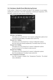
...], [Automatic Mode] and [Manual]. Configuration options: [Level 1] to monitor the status of the hardware on your system, including the parameters of the CPU temperature, motherboard temperature, CPU fan speed, chassis fan speed, and the critical voltage. The default value is [Full On]. The default value is [Enabled]. 84 The default is [Full On]. The default value is value [Level 4]. 3.6 Hardware Health Event Monitoring Screen In this to enable or disable Over Temperature Protection. Over Temperature Protection Use this...
...], [Automatic Mode] and [Manual]. Configuration options: [Level 1] to monitor the status of the hardware on your system, including the parameters of the CPU temperature, motherboard temperature, CPU fan speed, chassis fan speed, and the critical voltage. The default value is [Full On]. The default value is [Enabled]. 84 The default is [Full On]. The default value is value [Level 4]. 3.6 Hardware Health Event Monitoring Screen In this to enable or disable Over Temperature Protection. Over Temperature Protection Use this...

User Manual
Page 88
... Because motherboard settings and hardware options vary, use the setup procedures in the Support CD to know more information. 4.2 Support CD Information The Support CD that came with the motherboard contains necessary drivers and useful utilities that the motherboard supports. Please install the necessary drivers to your computer. or you need to contact ASRock or want to display the menu. 4.2.2 Drivers Menu The Drivers Menu shows the available device's drivers if the system detects installed devices. Chapter 4: Software Support 4.1 Install...
... Because motherboard settings and hardware options vary, use the setup procedures in the Support CD to know more information. 4.2 Support CD Information The Support CD that came with the motherboard contains necessary drivers and useful utilities that the motherboard supports. Please install the necessary drivers to your computer. or you need to contact ASRock or want to display the menu. 4.2.2 Drivers Menu The Drivers Menu shows the available device's drivers if the system detects installed devices. Chapter 4: Software Support 4.1 Install...
Quick Installation Guide
Page 2
...) 37 PCI Express 2.0 x1 Slot (PCIE6, Black) 17 Reset Switch (RSTBTN) 38 PCI Express 3.0 x16 Slot (PCIE5, Black) 18 Power Switch (PWRBTN) 39 PCI Express 2.0 x16 Slot (PCIE4, Black) 19 Power LED Header (PLED1) 40 PCI Express 3.0 x16 Slot (PCIE3, Black) 20 System Panel Header (PANEL1, Black) 41 PCI Express 3.0 x16 Slot (PCIE2, Black) 21 Chassis Speaker Header (SPEAKER1, Black) 42 PCI Express 3.0 x16 Slot (PCIE1, Black) 22 Clear CMOS Jumper (CLRCMOS1) 43 SLI / XFIRE Power Connector 23 SPI Flash Memory (64Mb) 44 Chassis Fan Connector (CHA_FAN3) 2 ASRock Z77 WS Motherboard English
...) 37 PCI Express 2.0 x1 Slot (PCIE6, Black) 17 Reset Switch (RSTBTN) 38 PCI Express 3.0 x16 Slot (PCIE5, Black) 18 Power Switch (PWRBTN) 39 PCI Express 2.0 x16 Slot (PCIE4, Black) 19 Power LED Header (PLED1) 40 PCI Express 3.0 x16 Slot (PCIE3, Black) 20 System Panel Header (PANEL1, Black) 41 PCI Express 3.0 x16 Slot (PCIE2, Black) 21 Chassis Speaker Header (SPEAKER1, Black) 42 PCI Express 3.0 x16 Slot (PCIE1, Black) 22 Clear CMOS Jumper (CLRCMOS1) 43 SLI / XFIRE Power Connector 23 SPI Flash Memory (64Mb) 44 Chassis Fan Connector (CHA_FAN3) 2 ASRock Z77 WS Motherboard English
Quick Installation Guide
Page 3
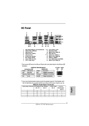
... connection LAN Port ** If you use 2-channel speaker, please connect the speaker's plug into "Front Speaker Jack". TABLE for the LAN port LED indications. See the table below for Audio Output Connection Audio Output Channels Front Speaker Rear Speaker Central / Bass Line In or (No. 10) (No. 7) (No. 6) Side Speaker (No. 9) 2 V -- -- -- 4 V V -- -- 6 V V V -- 8 V V V V English 3 ASRock Z77 WS Motherboard Please refer to the LAN port. I/O Panel 1 23 45 69 7 10 8 11 18 17 16 15 14 13 12 1 PS/2 Keyboard/Mouse Port...
... connection LAN Port ** If you use 2-channel speaker, please connect the speaker's plug into "Front Speaker Jack". TABLE for the LAN port LED indications. See the table below for Audio Output Connection Audio Output Channels Front Speaker Rear Speaker Central / Bass Line In or (No. 10) (No. 7) (No. 6) Side Speaker (No. 9) 2 V -- -- -- 4 V V -- -- 6 V V V -- 8 V V V V English 3 ASRock Z77 WS Motherboard Please refer to the LAN port. I/O Panel 1 23 45 69 7 10 8 11 18 17 16 15 14 13 12 1 PS/2 Keyboard/Mouse Port...

Quick Installation Guide
Page 8
...- ACPI 1.1 Compliance Wake Up Events - SMBIOS 2.3.1 Support - CPU Temperature Sensing - Chassis Temperature Sensing - Front panel audio connector - 3 x USB 2.0 headers (support 6 USB 2.0 ports) - 2 x USB 3.0 headers (support 4 USB 3.0 ports) - 1 x Dr. Debug with LED - 1 x Power Switch with LED - 1 x Reset Switch with LED - 1 x Clear CMOS Switch with LED - 64Mb AMI UEFI Legal BIOS with GUI support - Drivers, Utilities, AntiVirus Software (Trial Version), CyberLink MediaEspresso 6.5 Trial, ASRock MAGIX Multimedia Suite - CPU/Chassis Fan Multi-Speed Control ASRock Z77 WS Motherboard...
...- ACPI 1.1 Compliance Wake Up Events - SMBIOS 2.3.1 Support - CPU Temperature Sensing - Chassis Temperature Sensing - Front panel audio connector - 3 x USB 2.0 headers (support 6 USB 2.0 ports) - 2 x USB 3.0 headers (support 4 USB 3.0 ports) - 1 x Dr. Debug with LED - 1 x Power Switch with LED - 1 x Reset Switch with LED - 1 x Clear CMOS Switch with LED - 64Mb AMI UEFI Legal BIOS with GUI support - Drivers, Utilities, AntiVirus Software (Trial Version), CyberLink MediaEspresso 6.5 Trial, ASRock MAGIX Multimedia Suite - CPU/Chassis Fan Multi-Speed Control ASRock Z77 WS Motherboard...
Quick Installation Guide
Page 10
... your OC settings as a profile and share it fully utilizes the memory space that the USB flash drive or hard drive must use FAT32/16/12 file system. 10 ASRock Z77 WS Motherboard English Just launch this utility, you to update system BIOS without preparing an additional floppy diskette or other complicated flash utility. In XFast RAM, it with your BIOS only in...
... your OC settings as a profile and share it fully utilizes the memory space that the USB flash drive or hard drive must use FAT32/16/12 file system. 10 ASRock Z77 WS Motherboard English Just launch this utility, you to update system BIOS without preparing an additional floppy diskette or other complicated flash utility. In XFast RAM, it with your BIOS only in...
Quick Installation Guide
Page 32
... previously installed Catalyst drivers prior to uninstall any VGA driver installed in your Windows® taskbar. Step 3. Step 5. You must have Windows® XP Service Pack 2 or higher installed in your system. ATI Catalyst Control Center English 32 ASRock Z77 WS Motherboard We recommend using this utility to installation. For Windows® XP OS: A. Install the VGA card drivers to your computer. 2.8.2 Driver Installation and Setup Step 1. Power on your system, there is an optional download. Step 2. Remove the AMD driver...
... previously installed Catalyst drivers prior to uninstall any VGA driver installed in your Windows® taskbar. Step 3. Step 5. You must have Windows® XP Service Pack 2 or higher installed in your system. ATI Catalyst Control Center English 32 ASRock Z77 WS Motherboard We recommend using this utility to installation. For Windows® XP OS: A. Install the VGA card drivers to your computer. 2.8.2 Driver Installation and Setup Step 1. Power on your system, there is an optional download. Step 2. Remove the AMD driver...
Quick Installation Guide
Page 42
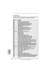
Serial Presence Detect (SPD) data reading Memory initialization. Configuring memory Memory initialization (other) Reserved for ASL Memory Installed CPU post-memory initialization is used Power on. Status Code 0x00 0x01 ...used to provide code information, which makes troubleshooting even easier. Application Processor(s) (AP) initialization CPU post-memory initialization. System Management Mode (SMM) initialization ASRock Z77 WS Motherboard English 2.12 Dr. Debug Dr. Debug is started Pre-memory South Bridge initialization (South Bridge module specific) Pre-memory...
Serial Presence Detect (SPD) data reading Memory initialization. Configuring memory Memory initialization (other) Reserved for ASL Memory Installed CPU post-memory initialization is used Power on. Status Code 0x00 0x01 ...used to provide code information, which makes troubleshooting even easier. Application Processor(s) (AP) initialization CPU post-memory initialization. System Management Mode (SMM) initialization ASRock Z77 WS Motherboard English 2.12 Dr. Debug Dr. Debug is started Pre-memory South Bridge initialization (South Bridge module specific) Pre-memory...
Quick Installation Guide
Page 206
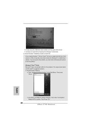
Follow Windows® Installation Guide to confirm. Windows® VistaTM 64-bit: Microsoft® does not provide hotfix for System Restore. b. F. Disable System Restore. a. De-select Local Disks for this problem. Then Press "Ok". 206 ASRock Z77 WS Motherboard English If you will need to boot into Windows® or install driver/ utilities. Continue to install OS by following instructions to fix this problem. The steps listed below are...
Follow Windows® Installation Guide to confirm. Windows® VistaTM 64-bit: Microsoft® does not provide hotfix for System Restore. b. F. Disable System Restore. a. De-select Local Disks for this problem. Then Press "Ok". 206 ASRock Z77 WS Motherboard English If you will need to boot into Windows® or install driver/ utilities. Continue to install OS by following instructions to fix this problem. The steps listed below are...


