
User Manual
Page 13
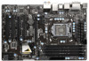
...EuP Ready LAN PHY 35 PCIE2 USB3_0_1 1 10 PCI Express 3.0 CMOS Battery Intel 11 Z77 34 PCI1 Super I/O XFast LAN XFast RAM 33 PCIE3 64Mb BIOS 12 SATA3 6Gb/s Designed in Taipei XFast USB Z77 Pro4 13 SATA2_5 SATA2_4 32 AUDIO PCI2 CODEC 14 RoHS SATA2_3 31 ... (DDR3_A1, DDR3_B1, Black) (CIR1, Gray) 6 2 x 240-pin DDR3 DIMM Slots 26 Infrared Module Header (IR1) (DDR3_A2, DDR3_B2, Black) 27 Clear CMOS Jumper (CLRCMOS1) 7 ATX Power Connector (ATXPWR1) 28 COM Port Header (COM1) 8 SATA3 Connectors (SATA3_A1, Gray) 29 HDMI_SPDIF Header 9 SATA3 Connectors (SATA3_A2...
...EuP Ready LAN PHY 35 PCIE2 USB3_0_1 1 10 PCI Express 3.0 CMOS Battery Intel 11 Z77 34 PCI1 Super I/O XFast LAN XFast RAM 33 PCIE3 64Mb BIOS 12 SATA3 6Gb/s Designed in Taipei XFast USB Z77 Pro4 13 SATA2_5 SATA2_4 32 AUDIO PCI2 CODEC 14 RoHS SATA2_3 31 ... (DDR3_A1, DDR3_B1, Black) (CIR1, Gray) 6 2 x 240-pin DDR3 DIMM Slots 26 Infrared Module Header (IR1) (DDR3_A2, DDR3_B2, Black) 27 Clear CMOS Jumper (CLRCMOS1) 7 ATX Power Connector (ATXPWR1) 28 COM Port Header (COM1) 8 SATA3 Connectors (SATA3_A1, Gray) 29 HDMI_SPDIF Header 9 SATA3 Connectors (SATA3_A2...

User Manual
Page 31
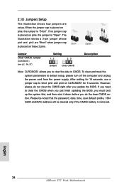
... system parameters to short pin2 and pin3 on these 2 pins. However, please do the clear-CMOS action. If you update the BIOS. Jumper Clear CMOS Jumper (CLRCMOS1) (see p.13, No. 27) Setting Default Clear CMOS Description Note: CLRCMOS1 allows you to clear the CMOS when you just finish updating the BIOS, you must boot up the system first...
... system parameters to short pin2 and pin3 on these 2 pins. However, please do the clear-CMOS action. If you update the BIOS. Jumper Clear CMOS Jumper (CLRCMOS1) (see p.13, No. 27) Setting Default Clear CMOS Description Note: CLRCMOS1 allows you to clear the CMOS when you just finish updating the BIOS, you must boot up the system first...

Quick Installation Guide
Page 2
... Slots 25 Consumer Infrared Module Header (DDR3_A1, DDR3_B1, Black) (CIR1, Gray) 6 2 x 240-pin DDR3 DIMM Slots 26 Infrared Module Header (IR1) (DDR3_A2, DDR3_B2, Black) 27 Clear CMOS Jumper (CLRCMOS1) 7 ATX Power Connector (ATXPWR1) 28 COM Port Header (COM1) 8 SATA3 Connectors (SATA3_A1, Gray) 29 HDMI_SPDIF Header 9 SATA3 Connectors (SATA3_A2, Gray) (HDMI_SPDIF1, Black) ... (SATA2_5, Black) 37 Power Fan Connector (PWR_FAN1) 19 Chassis Speaker Header (SPEAKER1, Black) 38 Chassis Fan Connector (CHA_FAN1) 20 System Panel Header (PANEL1, Black) English 2 ASRock Z77 Pro4 Motherboard
... Slots 25 Consumer Infrared Module Header (DDR3_A1, DDR3_B1, Black) (CIR1, Gray) 6 2 x 240-pin DDR3 DIMM Slots 26 Infrared Module Header (IR1) (DDR3_A2, DDR3_B2, Black) 27 Clear CMOS Jumper (CLRCMOS1) 7 ATX Power Connector (ATXPWR1) 28 COM Port Header (COM1) 8 SATA3 Connectors (SATA3_A1, Gray) 29 HDMI_SPDIF Header 9 SATA3 Connectors (SATA3_A2, Gray) (HDMI_SPDIF1, Black) ... (SATA2_5, Black) 37 Power Fan Connector (PWR_FAN1) 19 Chassis Speaker Header (SPEAKER1, Black) 38 Chassis Fan Connector (CHA_FAN1) 20 System Panel Header (PANEL1, Black) English 2 ASRock Z77 Pro4 Motherboard
Quick Installation Guide
Page 28
... is "Open". 2.10 Jumpers Setup The illustration shows how jumpers are "Short" when jumper cap is placed on these 2 pins. English 28 ASRock Z77 Pro4 Motherboard However, please do the clear-CMOS action. If you update the BIOS. If no jumper cap is placed on pins, the jumper is "Short". After waiting for 5 seconds. When...
... is "Open". 2.10 Jumpers Setup The illustration shows how jumpers are "Short" when jumper cap is placed on these 2 pins. English 28 ASRock Z77 Pro4 Motherboard However, please do the clear-CMOS action. If you update the BIOS. If no jumper cap is placed on pins, the jumper is "Short". After waiting for 5 seconds. When...

