
Intel Rapid Storage Guide
Page 12
... the Intel Rapid Storage Technology option ROM status screen appears during operating system setup. Enable RAID in System BIOS Use the instructions included with your motherboard to enter the option ROM user interface. 2. Click the Storage Configuration menu. 4. How to install an operating system onto a RAID volume (F6 install method) In...
... the Intel Rapid Storage Technology option ROM status screen appears during operating system setup. Enable RAID in System BIOS Use the instructions included with your motherboard to enter the option ROM user interface. 2. Click the Storage Configuration menu. 4. How to install an operating system onto a RAID volume (F6 install method) In...

User Manual
Page 2
... for backup purpose, without notice, and should not be constructed as a commitment by ASRock. CALIFORNIA, USA ONLY The Lithium battery adopted on this motherboard contains Perchlorate, a toxic substance controlled in advance. With respect to the contents of this manual, ASRock does not provide warranty of any kind, either expressed or implied, including but...
... for backup purpose, without notice, and should not be constructed as a commitment by ASRock. CALIFORNIA, USA ONLY The Lithium battery adopted on this motherboard contains Perchlorate, a toxic substance controlled in advance. With respect to the contents of this manual, ASRock does not provide warranty of any kind, either expressed or implied, including but...

User Manual
Page 3
Contents 1 Introduction 5 1.1 Package Contents 5 1.2 Specifications 6 1.3 Motherboard Layout 13 1.4 I/O Panel 14 2 Installation 16 2.1 Screw Holes 16 2.2 Pre-installation Precautions 16 2.3 CPU Installation 17 2.4 Installation of Heatsink and CPU fan 19... 20 2.6 Expansion Slots (PCI and PCI Express Slots 22 2.7 CrossFireXTM and Quad CrossFireXTM Operation Guide 23 2.8 Dual Monitor and Surround Display Features 27 2.9 ASRock Smart Remote Installation Guide 30 2.10 Jumpers Setup 31 2.11 Onboard Headers and Connectors 32 2.12 Serial ATA (SATA) / Serial ATA2 (SATA2) Hard Disks...
Contents 1 Introduction 5 1.1 Package Contents 5 1.2 Specifications 6 1.3 Motherboard Layout 13 1.4 I/O Panel 14 2 Installation 16 2.1 Screw Holes 16 2.2 Pre-installation Precautions 16 2.3 CPU Installation 17 2.4 Installation of Heatsink and CPU fan 19... 20 2.6 Expansion Slots (PCI and PCI Express Slots 22 2.7 CrossFireXTM and Quad CrossFireXTM Operation Guide 23 2.8 Dual Monitor and Surround Display Features 27 2.9 ASRock Smart Remote Installation Guide 30 2.10 Jumpers Setup 31 2.11 Onboard Headers and Connectors 32 2.12 Serial ATA (SATA) / Serial ATA2 (SATA2) Hard Disks...
User Manual
Page 5
... BIOS setup, please refer to the "User Manual" in Storage Configuration to set the BIOS option in our support CD for purchasing ASRock Z77 Pro3 motherboard, a reliable motherboard produced under ASRock's consistently stringent quality control. To get better performance in Windows® 7 / 7 64-bit / VistaTM / VistaTM 64bit, it is recommended to AHCI mode. Because...
... BIOS setup, please refer to the "User Manual" in Storage Configuration to set the BIOS option in our support CD for purchasing ASRock Z77 Pro3 motherboard, a reliable motherboard produced under ASRock's consistently stringent quality control. To get better performance in Windows® 7 / 7 64-bit / VistaTM / VistaTM 64bit, it is recommended to AHCI mode. Because...
User Manual
Page 9
...-bit / XP / XP 64-bit compliant (see CAUTION 23) * For detailed product information, please visit our website: http://www.asrock.com WARNING Please realize that Windows® cannot use. 4. CAUTION! 1. This motherboard supports Dual Channel Memory Technology. Only PCIE2 slot supports Gen 3 speed. CPU/Chassis/Power Fan Tachometer - The maximum shared memory...
...-bit / XP / XP 64-bit compliant (see CAUTION 23) * For detailed product information, please visit our website: http://www.asrock.com WARNING Please realize that Windows® cannot use. 4. CAUTION! 1. This motherboard supports Dual Channel Memory Technology. Only PCIE2 slot supports Gen 3 speed. CPU/Chassis/Power Fan Tachometer - The maximum shared memory...
User Manual
Page 10
...under Windows® 7 64-bit / 7 / VistaTM 64-bit / VistaTM. 7. In Hardware Monitor, it shows the major readings of output phases to access ASRock Instant Flash. In OC DNA, you can press the key during the POST or the key to enter into Standby mode (S1), Suspend to your...;ash utility embedded in a few clicks without preparing an additional floppy diskette or other complicated flash utility. For audio output, this motherboard supports both stereo and mono modes. In IES (Intelligent Energy Saver), the voltage regulator can load the OC profile to their own system...
...under Windows® 7 64-bit / 7 / VistaTM 64-bit / VistaTM. 7. In Hardware Monitor, it shows the major readings of output phases to access ASRock Instant Flash. In OC DNA, you can press the key during the POST or the key to enter into Standby mode (S1), Suspend to your...;ash utility embedded in a few clicks without preparing an additional floppy diskette or other complicated flash utility. For audio output, this motherboard supports both stereo and mono modes. In IES (Intelligent Energy Saver), the voltage regulator can load the OC profile to their own system...
User Manual
Page 11
...utilizes the memory space that BIOS files need to update their lifespan. 15. Only USB2.0 ports support this feature. 16. ASRock XFast USB can watch Youtube HD videos and download simultaneously. Real-Time Analysis of Your Data: With the status window, you can ...users from [Everyday], [Day of the week] or [Weekdays and weekends], then schedule the starting and ending hours of failing. 11. ASRock motherboards are transferring currently. 14. The performance may choose from bypassing OMG, guest accounts without permission to extend their BIOS without fear of internet...
...utilizes the memory space that BIOS files need to update their lifespan. 15. Only USB2.0 ports support this feature. 16. ASRock XFast USB can watch Youtube HD videos and download simultaneously. Real-Time Analysis of Your Data: With the status window, you can ...users from [Everyday], [Day of the week] or [Weekdays and weekends], then schedule the starting and ending hours of failing. 11. ASRock motherboards are transferring currently. 14. The performance may choose from bypassing OMG, guest accounts without permission to extend their BIOS without fear of internet...
User Manual
Page 12
...64258;exible option to perform over-clocking. According to Intel's suggestion, the EuP ready power supply must meet EuP standards, an EuP ready motherboard and an EuP ready power supply are not supported by the European Union to check with the power supply manufacturer for Energy Using Product,... selection, we recommend you install the PC system. 21. Please be noticed that ensures users the most convenient computing environment. 19. ASRock On/Off Play Technology allows users to enjoy the great audio experience from portable audio devices, such as MP3 players or mobile phones ...
...64258;exible option to perform over-clocking. According to Intel's suggestion, the EuP ready power supply must meet EuP standards, an EuP ready motherboard and an EuP ready power supply are not supported by the European Union to check with the power supply manufacturer for Energy Using Product,... selection, we recommend you install the PC system. 21. Please be noticed that ensures users the most convenient computing environment. 19. ASRock On/Off Play Technology allows users to enjoy the great audio experience from portable audio devices, such as MP3 players or mobile phones ...
User Manual
Page 13
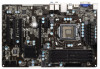
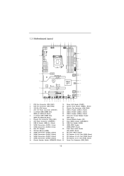
1.3 Motherboard Layout 12 3 19.3cm (7.6 in) 4 5 6 USB 2.0 T: USB0 B: USB1 PS2 Keyboard 35 VGA1 PWR_FAN1 CPU_FAN1 CPU_FAN2 ...BASS 9 Top: LINE IN Center: FRONT Bottom: MIC IN ErP/EuP Ready 34 PCIE1 Z77 Pro3 LAN PHY PCIE2 PCI Express 3.0 SATA3_1 SATA3_0 10 11 CMOS 33 Battery Super I/O XFast LAN XFast USB XFast ...) 10 SATA3 Connectors (SATA3_1, Gray) 29 HDMI_SPDIF Header 11 SATA3 Connectors (SATA3_0, Gray) (HDMI_SPDIF1, Black) 12 Intel Z77 Chipset 30 Front Panel Audio Header 13 SPI Flash Memory (64Mb) (HD_AUDIO1, Black) 14 SATA2 Connectors (SATA2_2, Black) 31...
1.3 Motherboard Layout 12 3 19.3cm (7.6 in) 4 5 6 USB 2.0 T: USB0 B: USB1 PS2 Keyboard 35 VGA1 PWR_FAN1 CPU_FAN1 CPU_FAN2 ...BASS 9 Top: LINE IN Center: FRONT Bottom: MIC IN ErP/EuP Ready 34 PCIE1 Z77 Pro3 LAN PHY PCIE2 PCI Express 3.0 SATA3_1 SATA3_0 10 11 CMOS 33 Battery Super I/O XFast LAN XFast USB XFast ...) 10 SATA3 Connectors (SATA3_1, Gray) 29 HDMI_SPDIF Header 11 SATA3 Connectors (SATA3_0, Gray) (HDMI_SPDIF1, Black) 12 Intel Z77 Chipset 30 Front Panel Audio Header 13 SPI Flash Memory (64Mb) (HD_AUDIO1, Black) 14 SATA2 Connectors (SATA2_2, Black) 31...
User Manual
Page 16
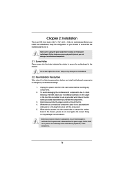
...holes indicated by the edges and do so may damage the motherboard. 2.2 Pre-installation Precautions Take note of your motherboard directly on a grounded anti- Failure to unplug the power cord before you install motherboard components or change any components. 2. Make sure to do... cord is an ATX form factor (12.0" x 7.6", 30.5 x 19.3 cm) motherboard. Before you install the motherboard, study the configuration of the following precautions before touching any motherboard settings. 1. Chapter 2: Installation This is detached from the wall socket before you handle the...
...holes indicated by the edges and do so may damage the motherboard. 2.2 Pre-installation Precautions Take note of your motherboard directly on a grounded anti- Failure to unplug the power cord before you install motherboard components or change any components. 2. Make sure to do... cord is an ATX form factor (12.0" x 7.6", 30.5 x 19.3 cm) motherboard. Before you install the motherboard, study the configuration of the following precautions before touching any motherboard settings. 1. Chapter 2: Installation This is detached from the wall socket before you handle the...
User Manual
Page 17
... the lever positioned at about 135 degrees in the socket. This cap must be seriously damaged. Otherwise, the CPU will be placed if returning the motherboard for after service. 17 Step 1. Do not force to insert the CPU into the socket, please check if the CPU surface is found. Remove the...
... the lever positioned at about 135 degrees in the socket. This cap must be seriously damaged. Otherwise, the CPU will be placed if returning the motherboard for after service. 17 Step 1. Do not force to insert the CPU into the socket, please check if the CPU surface is found. Remove the...
User Manual
Page 19
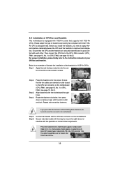
... on fastener caps with thumb to install and lock. Secure redundant cable with tie-wrap to ensure the cable does not interfere with the motherboard throughholes. Before you install the heatsink, you press down on side closest to MB header Fastener slots pointing straight out Press Down (4 Places... on the socket's surface. Step 4. Align fasteners with fan operation or contact other . Step 6. 2.4 Installation of CPU Fan and Heatsink This motherboard is an example to illustrate the installation of the heatsink for Socket LGA 1155/1156 CPU fan. 19 ter of the IHS on the...
... on fastener caps with thumb to install and lock. Secure redundant cable with tie-wrap to ensure the cable does not interfere with the motherboard throughholes. Before you install the heatsink, you press down on side closest to MB header Fastener slots pointing straight out Press Down (4 Places... on the socket's surface. Step 4. Align fasteners with fan operation or contact other . Step 6. 2.4 Installation of CPU Fan and Heatsink This motherboard is an example to illustrate the installation of the heatsink for Socket LGA 1155/1156 CPU fan. 19 ter of the IHS on the...
User Manual
Page 20
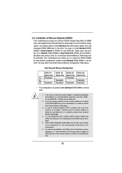
...If a pair of memory modules is NOT installed in the same Dual Channel, for example, installing a pair of Memory Modules (DIMM) This motherboard provides four 240-pin DDR3 (Double Data Rate 3) DIMM slots, and supports Dual Channel Memory Technology. It is not recommended to install them ...Dual Channel Memory Configuration DDR3_A1 DDR3_A2 DDR3_B1 DDR3_B2 (Black Slot) (Black Slot) (Black Slot) (Black Slot) (1) Populated - otherwise, this motherboard and DIMM may refer to install four DDR3 DIMMs for optimal compatibility and reliability, it is not allowed to install them on this...
...If a pair of memory modules is NOT installed in the same Dual Channel, for example, installing a pair of Memory Modules (DIMM) This motherboard provides four 240-pin DDR3 (Double Data Rate 3) DIMM slots, and supports Dual Channel Memory Technology. It is not recommended to install them ...Dual Channel Memory Configuration DDR3_A1 DDR3_A2 DDR3_B1 DDR3_B2 (Black Slot) (Black Slot) (Black Slot) (Black Slot) (1) Populated - otherwise, this motherboard and DIMM may refer to install four DDR3 DIMMs for optimal compatibility and reliability, it is not allowed to install them on this...

User Manual
Page 21
... Step 2. Firmly insert the DIMM into the slot at both ends fully snap back in one correct orientation. Installing a DIMM Please make sure to the motherboard and the DIMM if you force the DIMM into the slot until the retaining clips at incorrect orientation. Unlock a DIMM slot by pressing the retaining...
... Step 2. Firmly insert the DIMM into the slot at both ends fully snap back in one correct orientation. Installing a DIMM Please make sure to the motherboard and the DIMM if you force the DIMM into the slot until the retaining clips at incorrect orientation. Unlock a DIMM slot by pressing the retaining...

User Manual
Page 22
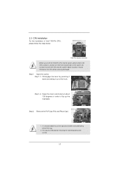
... PCIE2 and PCIE3 slots. To run only at x4 bandwidth. 3. PCIE2 (PCIE 3.0 x16 slot) is completely seated on PCIE2 slot. 2. Fasten the card to the motherboard's chassis fan connector (CHA_FAN1 or CHA_FAN2) when using multiple graphics cards for PCI Express x16 lane width graphics cards, or to install PCI Express graphics... that have the 32-bit PCI interface. Keep the screws for a PCI Express x1 lane width card, such as a Gigabit LAN card, SATA2 card or ASRock Game Blaster, etc. Step 2. In CrossFireXTM mode, please install the PCI Express x16 graphics cards on this...
... PCIE2 and PCIE3 slots. To run only at x4 bandwidth. 3. PCIE2 (PCIE 3.0 x16 slot) is completely seated on PCIE2 slot. 2. Fasten the card to the motherboard's chassis fan connector (CHA_FAN1 or CHA_FAN2) when using multiple graphics cards for PCI Express x16 lane width graphics cards, or to install PCI Express graphics... that have the 32-bit PCI interface. Keep the screws for a PCI Express x1 lane width card, such as a Gigabit LAN card, SATA2 card or ASRock Game Blaster, etc. Step 2. In CrossFireXTM mode, please install the PCI Express x16 graphics cards on this...

User Manual
Page 23
...graphics card manuals for ATITM CrossFireXTM driver updates. 1. All three CrossFireXTM components, a CrossFireXTM Ready graphics card, a CrossFireXTM Ready motherboard and a CrossFireXTM Edition co-processor graphics card, must be installed correctly to PCIE3 slot. Currently CrossFireXTM feature is supported with.... Please check AMD website for detailed installation guide. Step 1. 2.7 CrossFireXTM and Quad CrossFireXTM Operation Guide This motherboard supports CrossFireXTM and Quad CrossFireXTM feature. For other Radeon graphics card to benefit from the CrossFireXTM multi-GPU...
...graphics card manuals for ATITM CrossFireXTM driver updates. 1. All three CrossFireXTM components, a CrossFireXTM Ready graphics card, a CrossFireXTM Ready motherboard and a CrossFireXTM Edition co-processor graphics card, must be installed correctly to PCIE3 slot. Currently CrossFireXTM feature is supported with.... Please check AMD website for detailed installation guide. Step 1. 2.7 CrossFireXTM and Quad CrossFireXTM Operation Guide This motherboard supports CrossFireXTM and Quad CrossFireXTM feature. For other Radeon graphics card to benefit from the CrossFireXTM multi-GPU...
User Manual
Page 24
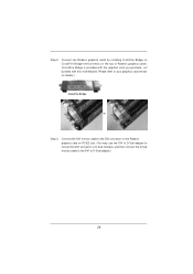
... the Radeon graphics card on the top of Radeon graphics cards. (CrossFire Bridge is provided with the graphics card you purchase, not bundled with this motherboard. Step 2. Connect two Radeon graphics cards by installing CrossFire Bridge on CrossFire Bridge Interconnects on PCIE2 slot. (You may use the DVI to D-Sub adapter...
... the Radeon graphics card on the top of Radeon graphics cards. (CrossFire Bridge is provided with the graphics card you purchase, not bundled with this motherboard. Step 2. Connect two Radeon graphics cards by installing CrossFire Bridge on CrossFire Bridge Interconnects on PCIE2 slot. (You may use the DVI to D-Sub adapter...

User Manual
Page 27
If you have already installed the onboard VGA driver from our support CD to this motherboard. This motherboard also provides independent display controllers for D-Sub and HDMI to the HDMI port on the I /O panel and connect a HDMI monitor cable to support dual ... after your computer. 27 To enable dual monitor feature, please follow the steps below: 1. 2.8 Dual Monitor and Surround Display Features Dual Monitor Feature This motherboard supports dual monitor feature. If you haven't installed the onboard VGA driver yet, please install the onboard VGA driver from our support CD to your...
If you have already installed the onboard VGA driver from our support CD to this motherboard. This motherboard also provides independent display controllers for D-Sub and HDMI to the HDMI port on the I /O panel and connect a HDMI monitor cable to support dual ... after your computer. 27 To enable dual monitor feature, please follow the steps below: 1. 2.8 Dual Monitor and Surround Display Features Dual Monitor Feature This motherboard supports dual monitor feature. If you haven't installed the onboard VGA driver yet, please install the onboard VGA driver from our support CD to your...
User Manual
Page 28
... to display a large number on VGA card is no need to enable the function of surround display feature. E. G. Surround Display Feature This motherboard supports surround display upgrade. If you do not adjust the UEFI setup, the default value of the multi-monitors according to this monitor". A....Express VGA card driver to set up a multi-monitor display. When you wish to six. 28 Click "Extend my Windows desktop onto this motherboard. 4. Please refer to the following steps to your system. B. D. Right-click the display icon in the Display Properties dialog that you ...
... to display a large number on VGA card is no need to enable the function of surround display feature. E. G. Surround Display Feature This motherboard supports surround display upgrade. If you do not adjust the UEFI setup, the default value of the multi-monitors according to this monitor". A....Express VGA card driver to set up a multi-monitor display. When you wish to six. 28 Click "Extend my Windows desktop onto this motherboard. 4. Please refer to the following steps to your system. B. D. Right-click the display icon in the Display Properties dialog that you ...
User Manual
Page 29
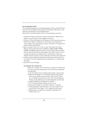
...-bit OS: Right click the desktop, choose "Personalize", and select the "Display Settings" tab so that you would like to use HDCP function with this motherboard, you move items from one monitor to another. D. A. Click and drag the display icons to positions representing the physical setup of content as well. Therefore...
...-bit OS: Right click the desktop, choose "Personalize", and select the "Display Settings" tab so that you would like to use HDCP function with this motherboard, you move items from one monitor to another. D. A. Click and drag the display icons to positions representing the physical setup of content as well. Therefore...


