User Manual
Page 5
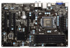
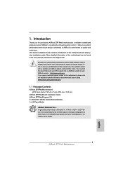
... cards and CPU support lists on ASRock website without notice. www.asrock.com/support/index.asp 1.1 Package Contents ASRock Z77 Pro3 Motherboard (ATX Form Factor: 12.0-in x 7.6-in, 30.5 cm x 19.3 cm) ASRock Z77 Pro3 Quick Installation Guide ASRock Z77 Pro3 Support CD 2 x Serial ATA (SATA) Data Cables (Optional) 1 x I/O Panel Shield ASRock Reminds You... ASRock website http://www.asrock.com If you are using. For...
... cards and CPU support lists on ASRock website without notice. www.asrock.com/support/index.asp 1.1 Package Contents ASRock Z77 Pro3 Motherboard (ATX Form Factor: 12.0-in x 7.6-in, 30.5 cm x 19.3 cm) ASRock Z77 Pro3 Quick Installation Guide ASRock Z77 Pro3 Support CD 2 x Serial ATA (SATA) Data Cables (Optional) 1 x I/O Panel Shield ASRock Reminds You... ASRock website http://www.asrock.com If you are using. For...
User Manual
Page 6
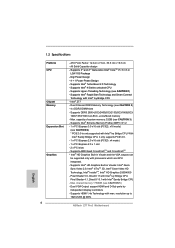
...4.1, DirectX 10.1 with Intel® Ivy Bridge CPU - Dual VGA Output: support HDMI and D-Sub ports by independent display controllers - ATX Form Factor: 12.0-in x 7.6-in LGA1155 Package - Supports DDR3 2800+(OC)/2400(OC)/2133(OC)/1866(OC)/ 1600/1333/1066 non-... 3) - resolution up to 1920x1200 @ 60Hz 6 Supports Intel® Rapid Start Technology and Smart Connect Technology with Intel® Sandy Bridge CPU - Intel® Z77 - capacity of system memory: 32GB (see CAUTION 5) - Supports Intel® Extreme Memory Profile (XMP)1.3/1.2 - 1 x PCI Express 3.0 x16 slot ...
...4.1, DirectX 10.1 with Intel® Ivy Bridge CPU - Dual VGA Output: support HDMI and D-Sub ports by independent display controllers - ATX Form Factor: 12.0-in x 7.6-in LGA1155 Package - Supports DDR3 2800+(OC)/2400(OC)/2133(OC)/1866(OC)/ 1600/1333/1066 non-... 3) - resolution up to 1920x1200 @ 60Hz 6 Supports Intel® Rapid Start Technology and Smart Connect Technology with Intel® Sandy Bridge CPU - Intel® Z77 - capacity of system memory: 32GB (see CAUTION 5) - Supports Intel® Extreme Memory Profile (XMP)1.3/1.2 - 1 x PCI Express 3.0 x16 slot ...
User Manual
Page 8
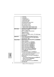
... - 1 x CIR header - 1 x COM port header - 1 x HDMI_SPDIF header - 1 x Power LED header - CPU/Chassis/Power FAN connector - 24 pin ATX power connector - 8 pin 12V power connector - ASRock Instant Boot - CPU Frequency Stepless Control (see CAUTION 10) - ASRock APP Charger (see CAUTION 19) - Lucid Virtu Universal MVP (see CAUTION 21) - Supports jumperfree - Combo Cooler Option (C.C.O.) (see...
... - 1 x CIR header - 1 x COM port header - 1 x HDMI_SPDIF header - 1 x Power LED header - CPU/Chassis/Power FAN connector - 24 pin ATX power connector - 8 pin 12V power connector - ASRock Instant Boot - CPU Frequency Stepless Control (see CAUTION 10) - ASRock APP Charger (see CAUTION 19) - Lucid Virtu Universal MVP (see CAUTION 21) - Supports jumperfree - Combo Cooler Option (C.C.O.) (see...
User Manual
Page 13
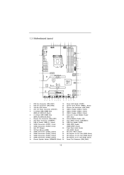
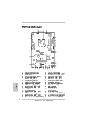
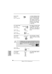
...: SIDE SPK Center: REAR SPK Bottom: CTR BASS 9 Top: LINE IN Center: FRONT Bottom: MIC IN ErP/EuP Ready 34 PCIE1 Z77 Pro3 LAN PHY PCIE2 PCI Express 3.0 SATA3_1 SATA3_0 10 11 CMOS 33 Battery Super I/O XFast LAN XFast USB XFast RAM 12 Intel...240-pin DDR3 DIMM Slots 25 Consumer Infrared Module Header (DDR3_A2, DDR3_B2, Black) (CIR1, Gray) 7 Chassis Fan Connector (CHA_FAN1) 26 Infrared Module Header (IR1) 8 ATX Power Connector (ATXPWR1) 27 Clear CMOS Jumper (CLRCMOS1) 9 USB 3.0 Header (USB3_0_1, Black) 28 COM Port Header (COM1) 10 SATA3 Connectors (SATA3_1, Gray) 29 ...
...: SIDE SPK Center: REAR SPK Bottom: CTR BASS 9 Top: LINE IN Center: FRONT Bottom: MIC IN ErP/EuP Ready 34 PCIE1 Z77 Pro3 LAN PHY PCIE2 PCI Express 3.0 SATA3_1 SATA3_0 10 11 CMOS 33 Battery Super I/O XFast LAN XFast USB XFast RAM 12 Intel...240-pin DDR3 DIMM Slots 25 Consumer Infrared Module Header (DDR3_A2, DDR3_B2, Black) (CIR1, Gray) 7 Chassis Fan Connector (CHA_FAN1) 26 Infrared Module Header (IR1) 8 ATX Power Connector (ATXPWR1) 27 Clear CMOS Jumper (CLRCMOS1) 9 USB 3.0 Header (USB3_0_1, Black) 28 COM Port Header (COM1) 10 SATA3 Connectors (SATA3_1, Gray) 29 ...
User Manual
Page 16
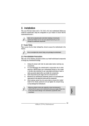
... the wall socket before you install motherboard components or change any component, ensure that the power is switched off or the power cord is an ATX form factor (12.0" x 7.6", 30.5 x 19.3 cm) motherboard. Before you uninstall any components. 2. Whenever you install the motherboard, study the configuration of the following...
... the wall socket before you install motherboard components or change any component, ensure that the power is switched off or the power cord is an ATX form factor (12.0" x 7.6", 30.5 x 19.3 cm) motherboard. Before you uninstall any components. 2. Whenever you install the motherboard, study the configuration of the following...
User Manual
Page 30
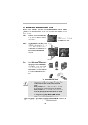
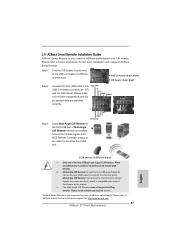
...to the other port will remain USB function. 2. Please install it on ASRock motherboard. GND IRTX IRRX ATX+5VSB Install Multi-Angle CIR Receiver to ASRock website for the motherboard support list: http://www.asrock.com 30 When the CIR function is only supported by some of the ... USB port can receive the multi-direction infrared signals (top, down and front), which is used for ASRock motherboard with most of ASRock motherboards. Step1. 2.9 ASRock Smart Remote Installation Guide ASRock Smart Remote is only used for front USB only. Connect the front USB cable to below , pin ...
...to the other port will remain USB function. 2. Please install it on ASRock motherboard. GND IRTX IRRX ATX+5VSB Install Multi-Angle CIR Receiver to ASRock website for the motherboard support list: http://www.asrock.com 30 When the CIR function is only supported by some of the ... USB port can receive the multi-direction infrared signals (top, down and front), which is used for ASRock motherboard with most of ASRock motherboards. Step1. 2.9 ASRock Smart Remote Installation Guide ASRock Smart Remote is only used for front USB only. Connect the front USB cable to below , pin ...
User Manual
Page 33
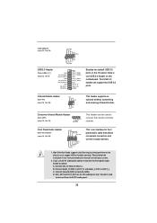
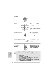
... chassis must support HDA to MIC2_L. Connect Mic_IN (MIC) to function correctly. B. Consumer Infrared Module Header (4-pin CIR1) (see p.13, No. 25) 1 GND IRTX IRRX ATX+5VSB This header can support two USB 3.0 ports. 1 Infrared Module Header (5-pin IR1) (see p.13, No. 26) IRTX +5VSB DUMMY 1 GND IRRX This header supports...
... chassis must support HDA to MIC2_L. Connect Mic_IN (MIC) to function correctly. B. Consumer Infrared Module Header (4-pin CIR1) (see p.13, No. 25) 1 GND IRTX IRRX ATX+5VSB This header can support two USB 3.0 ports. 1 Infrared Module Header (5-pin IR1) (see p.13, No. 26) IRTX +5VSB DUMMY 1 GND IRRX This header supports...
User Manual
Page 35
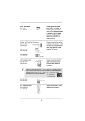
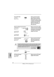
Pin 1-3 Connected 3-Pin Fan Installation (3-pin CPU_FAN2) (see p.13, No. 2) GND +12V CPU_FAN_SPEED ATX Power Connector (24-pin ATXPWR1) (see p.13, No. 8) 12 24 1 13 Please connect an ATX power supply to this motherboard provides 4-Pin CPU fan (Quiet Fan) support, the 3-Pin CPU fan still can work successfully even without the fan...
Pin 1-3 Connected 3-Pin Fan Installation (3-pin CPU_FAN2) (see p.13, No. 2) GND +12V CPU_FAN_SPEED ATX Power Connector (24-pin ATXPWR1) (see p.13, No. 8) 12 24 1 13 Please connect an ATX power supply to this motherboard provides 4-Pin CPU fan (Quiet Fan) support, the 3-Pin CPU fan still can work successfully even without the fan...
User Manual
Page 36
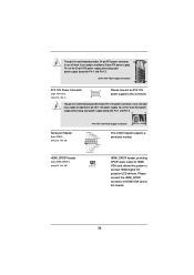
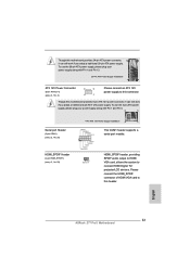
...supply along with Pin 1 and Pin 13. 20-Pin ATX Power Supply Installation 1 13 ATX 12V Power Connector (8-pin ATX12V1) (see p.13, No. 4) 8 5 4 1 Please connect an ATX 12V power supply to this connector. To use the 20-pin ATX power supply, please plug your power supply along with Pin... output to HDMI VGA card, allows the system to this header. 36 HDMI_SPDIF Header (2-pin HDMI_SPDIF1) (see p.13, No. 28) 4-Pin ATX 12V Power Supply Installation 4 1 This COM1 header supports a serial port module. Please connect the HDMI_SPDIF connector of HDMI VGA card to connect HDMI...
...supply along with Pin 1 and Pin 13. 20-Pin ATX Power Supply Installation 1 13 ATX 12V Power Connector (8-pin ATX12V1) (see p.13, No. 4) 8 5 4 1 Please connect an ATX 12V power supply to this connector. To use the 20-pin ATX power supply, please plug your power supply along with Pin... output to HDMI VGA card, allows the system to this header. 36 HDMI_SPDIF Header (2-pin HDMI_SPDIF1) (see p.13, No. 28) 4-Pin ATX 12V Power Supply Installation 4 1 This COM1 header supports a serial port module. Please connect the HDMI_SPDIF connector of HDMI VGA card to connect HDMI...
Quick Installation Guide
Page 2
... Fan Connector (CPU_FAN2) 20 System Panel Header (PANEL1, Black) 3 1155-Pin CPU Socket 21 Chassis Fan Connector (CHA_FAN2) 4 ATX 12V Power Connector (ATX12V1) 22 USB 2.0 Header (USB4_5, Black) 5 2 x 240-pin DDR3 DIMM Slots 23 USB 2.0 Header...Module Header (DDR3_A2, DDR3_B2, Black) (CIR1, Gray) 7 Chassis Fan Connector (CHA_FAN1) 26 Infrared Module Header (IR1) 8 ATX Power Connector (ATXPWR1) 27 Clear CMOS Jumper (CLRCMOS1) 9 USB 3.0 Header (USB3_0_1, Black) 28 COM Port Header (COM1) ... Header (SPEAKER1, Black) 35 Power Fan Connector (PWR_FAN1) 2 ASRock Z77 Pro3 Motherboard English
... Fan Connector (CPU_FAN2) 20 System Panel Header (PANEL1, Black) 3 1155-Pin CPU Socket 21 Chassis Fan Connector (CHA_FAN2) 4 ATX 12V Power Connector (ATX12V1) 22 USB 2.0 Header (USB4_5, Black) 5 2 x 240-pin DDR3 DIMM Slots 23 USB 2.0 Header...Module Header (DDR3_A2, DDR3_B2, Black) (CIR1, Gray) 7 Chassis Fan Connector (CHA_FAN1) 26 Infrared Module Header (IR1) 8 ATX Power Connector (ATXPWR1) 27 Clear CMOS Jumper (CLRCMOS1) 9 USB 3.0 Header (USB3_0_1, Black) 28 COM Port Header (COM1) ... Header (SPEAKER1, Black) 35 Power Fan Connector (PWR_FAN1) 2 ASRock Z77 Pro3 Motherboard English
Quick Installation Guide
Page 5
... it is recommended to set the BIOS option in , 30.5 cm x 19.3 cm) ASRock Z77 Pro3 Quick Installation Guide ASRock Z77 Pro3 Support CD 2 x Serial ATA (SATA) Data Cables (Optional) 1 x I/O Panel Shield ASRock Reminds You... Introduction Thank you are using. Because the motherboard specifications and the BIOS ...CD. 1. In case any modifications of the motherboard and step-bystep installation guide. www.asrock.com/support/index.asp 1.1 Package Contents ASRock Z77 Pro3 Motherboard (ATX Form Factor: 12.0-in x 7.6-in Storage Configuration to quality and endurance. For the ...
... it is recommended to set the BIOS option in , 30.5 cm x 19.3 cm) ASRock Z77 Pro3 Quick Installation Guide ASRock Z77 Pro3 Support CD 2 x Serial ATA (SATA) Data Cables (Optional) 1 x I/O Panel Shield ASRock Reminds You... Introduction Thank you are using. Because the motherboard specifications and the BIOS ...CD. 1. In case any modifications of the motherboard and step-bystep installation guide. www.asrock.com/support/index.asp 1.1 Package Contents ASRock Z77 Pro3 Motherboard (ATX Form Factor: 12.0-in x 7.6-in Storage Configuration to quality and endurance. For the ...
Quick Installation Guide
Page 6
...Intel® InsiderTM, Intel® HD Graphics 2500/4000 - shared memory 1760MB (see CAUTION 3) - resolution up to 1920x1200 @ 60Hz ASRock Z77 Pro3 Motherboard English Supports Intel® Rapid Start Technology and Smart Connect Technology with Intel® Ivy Bridge CPU. capacity of system memory: 32GB...® Ivy Bridge CPU - Supports 3rd and 2nd Generation Intel® CoreTM i7 / i5 / i3 in , 30.5 cm x 19.3 cm - ATX Form Factor: 12.0-in x 7.6-in LGA1155 Package - Max. Supports Intel® Turbo Boost 2.0 Technology - Supports Intel® K-Series unlocked CPU - ...
...Intel® InsiderTM, Intel® HD Graphics 2500/4000 - shared memory 1760MB (see CAUTION 3) - resolution up to 1920x1200 @ 60Hz ASRock Z77 Pro3 Motherboard English Supports Intel® Rapid Start Technology and Smart Connect Technology with Intel® Ivy Bridge CPU. capacity of system memory: 32GB...® Ivy Bridge CPU - Supports 3rd and 2nd Generation Intel® CoreTM i7 / i5 / i3 in , 30.5 cm x 19.3 cm - ATX Form Factor: 12.0-in x 7.6-in LGA1155 Package - Max. Supports Intel® Turbo Boost 2.0 Technology - Supports Intel® K-Series unlocked CPU - ...
Quick Installation Guide
Page 8
.../Chassis/Power FAN connector - 24 pin ATX power connector - 8 pin 12V power connector - CPU Frequency Stepless Control (see CAUTION 17) * Lucid Virtu Universal MVP can be supported only with GUI support - SMBIOS 2.3.1 Support - Boot Failure Guard (B.F.G.) - Lucid Virtu Universal MVP (see CAUTION 19) - Good Night LED ASRock Z77 Pro3 Motherboard Supports "Plug and Play...
.../Chassis/Power FAN connector - 24 pin ATX power connector - 8 pin 12V power connector - CPU Frequency Stepless Control (see CAUTION 17) * Lucid Virtu Universal MVP can be supported only with GUI support - SMBIOS 2.3.1 Support - Boot Failure Guard (B.F.G.) - Lucid Virtu Universal MVP (see CAUTION 19) - Good Night LED ASRock Z77 Pro3 Motherboard Supports "Plug and Play...
Quick Installation Guide
Page 13
... or the like. Before you install motherboard components or change any component, ensure that the power is switched off or the power cord is an ATX form factor (12.0" x 7.6", 30.5 x 19.3 cm) motherboard. To avoid damaging the motherboard's components due to static electricity, NEVER place ... Pre-installation Precautions Take note of your motherboard directly on a grounded anti- Failure to the motherboard, peripherals, and/or components. 13 ASRock Z77 Pro3 Motherboard English Doing so may cause severe damage to do not touch the ICs. 4. Whenever you handle the components. 3.
... or the like. Before you install motherboard components or change any component, ensure that the power is switched off or the power cord is an ATX form factor (12.0" x 7.6", 30.5 x 19.3 cm) motherboard. To avoid damaging the motherboard's components due to static electricity, NEVER place ... Pre-installation Precautions Take note of your motherboard directly on a grounded anti- Failure to the motherboard, peripherals, and/or components. 13 ASRock Z77 Pro3 Motherboard English Doing so may cause severe damage to do not touch the ICs. 4. Whenever you handle the components. 3.
Quick Installation Guide
Page 27
... 2.0 header on the rear panel. GND IRTX IRRX ATX+5VSB Install Multi-Angle CIR Receiver to ASRock website for the motherboard support list: http://www.asrock.com 27 ASRock Z77 Pro3 Motherboard Only one of ASRock motherboards. Multi-Angle CIR Receiver is used for ASRock motherboard with most of ASRock Smart Remote. Step1. Please make sure the wire assignments...
... 2.0 header on the rear panel. GND IRTX IRRX ATX+5VSB Install Multi-Angle CIR Receiver to ASRock website for the motherboard support list: http://www.asrock.com 27 ASRock Z77 Pro3 Motherboard Only one of ASRock motherboards. Multi-Angle CIR Receiver is used for ASRock motherboard with most of ASRock Smart Remote. Step1. Please make sure the wire assignments...
Quick Installation Guide
Page 30
... 3.0 header on this motherboard. Please follow the instruction in our manual and chassis manual to connect them for AC'97 audio panel. 30 ASRock Z77 Pro3 Motherboard English If you use AC'97 audio panel, please install it to connect the remote controller receiver. MIC_RET and OUT_RET are for HD... header can be used to the front panel audio header as below: A. Consumer Infrared Module Header (4-pin CIR1) (see p.2, No. 25) 1 GND IRTX IRRX ATX+5VSB This header can support two USB 3.0 ports. 1 Infrared Module Header (5-pin IR1) (see p.2, No. 26) IRTX +5VSB DUMMY 1 GND IRRX This header ...
... 3.0 header on this motherboard. Please follow the instruction in our manual and chassis manual to connect them for AC'97 audio panel. 30 ASRock Z77 Pro3 Motherboard English If you use AC'97 audio panel, please install it to connect the remote controller receiver. MIC_RET and OUT_RET are for HD... header can be used to the front panel audio header as below: A. Consumer Infrared Module Header (4-pin CIR1) (see p.2, No. 25) 1 GND IRTX IRRX ATX+5VSB This header can support two USB 3.0 ports. 1 Infrared Module Header (5-pin IR1) (see p.2, No. 26) IRTX +5VSB DUMMY 1 GND IRRX This header ...
Quick Installation Guide
Page 32
Please connect the fan cables to the fan connectors and match the black wire to the ground pin. English 32 ASRock Z77 Pro3 Motherboard The LED keeps blinking in S4 state or S5 state (power off). CHA_FAN1 and CHA_FAN2 supports Fan Control. (3-pin PWR_FAN1) (...still can work successfully even without the fan speed control function. Pin 1-3 Connected 3-Pin Fan Installation (3-pin CPU_FAN2) (see p.2, No. 2) GND +12V CPU_FAN_SPEED ATX Power Connector (24-pin ATXPWR1) (see p.2, No. 1) FAN_SPEED_CONTROL CPU_FAN_SPEED +12V GND 1 2 3 4 Please connect the CPU fan cable to the connector and...
Please connect the fan cables to the fan connectors and match the black wire to the ground pin. English 32 ASRock Z77 Pro3 Motherboard The LED keeps blinking in S4 state or S5 state (power off). CHA_FAN1 and CHA_FAN2 supports Fan Control. (3-pin PWR_FAN1) (...still can work successfully even without the fan speed control function. Pin 1-3 Connected 3-Pin Fan Installation (3-pin CPU_FAN2) (see p.2, No. 2) GND +12V CPU_FAN_SPEED ATX Power Connector (24-pin ATXPWR1) (see p.2, No. 1) FAN_SPEED_CONTROL CPU_FAN_SPEED +12V GND 1 2 3 4 Please connect the CPU fan cable to the connector and...
Quick Installation Guide
Page 33
English 33 ASRock Z77 Pro3 Motherboard HDMI_SPDIF Header (2-pin HDMI_SPDIF1) (see p.2, No. 28) 4-Pin ATX 12V Power Supply Installation 4 1 This COM1 header supports a serial port module. Please connect the HDMI_SPDIF connector of HDMI VGA card to this connector. To use the 20-pin ATX power supply, please... TV/ projector/LCD devices. Though this motherboard provides 8-pin ATX 12V power connector, it can still work if you adopt a traditional 4-pin ATX 12V power supply. Though this motherboard provides 24-pin ATX power connector, 12 24 it can still work if you ...
English 33 ASRock Z77 Pro3 Motherboard HDMI_SPDIF Header (2-pin HDMI_SPDIF1) (see p.2, No. 28) 4-Pin ATX 12V Power Supply Installation 4 1 This COM1 header supports a serial port module. Please connect the HDMI_SPDIF connector of HDMI VGA card to this connector. To use the 20-pin ATX power supply, please... TV/ projector/LCD devices. Though this motherboard provides 8-pin ATX 12V power connector, it can still work if you adopt a traditional 4-pin ATX 12V power supply. Though this motherboard provides 24-pin ATX power connector, 12 24 it can still work if you ...

Quick Installation Guide
Page 136
...) 을 OUT2_R Audio_L (LIN) 을 OUT2_L C. MIC_RET 및 OUT_RET 는 HD 이들을 AC'97 한 국 어 136 ASRock Z77 Pro3 Motherboard (9 핀 USB8_9) (2 24 USB_PWR P-9 P+9 GND DUMMY 1 GND P+8 P-8 USB_PWR USB 3.0 헤더 (19 핀 USB3_0_1) (2 9 Vbus ... 의 USB 3.0 1 (5 핀 IR1) (2 26 (4 핀 CIR1) (2 25 IRTX +5VSB DUMMY 1 GND IRRX 1 GND IRTX IRRX ATX+5VSB (9 핀 HD_AUDIO1) (2 30 GND PRESENCE# MIC_RET OUT_RET 1 OUT2_L J_SENSE OUT2_R MIC2_R MIC2_L 1.
...) 을 OUT2_R Audio_L (LIN) 을 OUT2_L C. MIC_RET 및 OUT_RET 는 HD 이들을 AC'97 한 국 어 136 ASRock Z77 Pro3 Motherboard (9 핀 USB8_9) (2 24 USB_PWR P-9 P+9 GND DUMMY 1 GND P+8 P-8 USB_PWR USB 3.0 헤더 (19 핀 USB3_0_1) (2 9 Vbus ... 의 USB 3.0 1 (5 핀 IR1) (2 26 (4 핀 CIR1) (2 25 IRTX +5VSB DUMMY 1 GND IRRX 1 GND IRTX IRRX ATX+5VSB (9 핀 HD_AUDIO1) (2 30 GND PRESENCE# MIC_RET OUT_RET 1 OUT2_L J_SENSE OUT2_R MIC2_R MIC2_L 1.
Quick Installation Guide
Page 138
..., 및 CHA_FAN2 GND +12V PWR_FAN_SPEED CPU (4 핀 CPU_FAN1) (2 1 FAN_SPEED_CONTROL CPU_FAN_SPEED +12V GND CPU 1 2 3 4 4 핀 CPU 3 핀 CPU CPU 3 핀 CPU 1-3 1-3 3 (3 핀 CPU_FAN2) (2 2 GND +12V CPU_FAN_SPEED ATX (24 핀 ATXPWR1) (2 8 12 24 1 13 ATX 한 국 어 138 ASRock Z77 Pro3 Motherboard
..., 및 CHA_FAN2 GND +12V PWR_FAN_SPEED CPU (4 핀 CPU_FAN1) (2 1 FAN_SPEED_CONTROL CPU_FAN_SPEED +12V GND CPU 1 2 3 4 4 핀 CPU 3 핀 CPU CPU 3 핀 CPU 1-3 1-3 3 (3 핀 CPU_FAN2) (2 2 GND +12V CPU_FAN_SPEED ATX (24 핀 ATXPWR1) (2 8 12 24 1 13 ATX 한 국 어 138 ASRock Z77 Pro3 Motherboard