User Manual
Page 12
... is not recommended to adopt three different CPU cooler types, Socket LGA 775, LGA 1155 and LGA 1156. To improve heat dissipation, remember to define the power consumption for the completed system. ASRock XFast RAM is not supported by the European Union to spray thermal grease between the ... automatically shutdown. EuP stands for more details. 12 For EuP ready power supply selection, we recommend you install the PC system. 21. ASRock On/Off Play Technology allows users to enjoy the great audio experience from portable audio devices, such as MP3 players or mobile phones to check...
... is not recommended to adopt three different CPU cooler types, Socket LGA 775, LGA 1155 and LGA 1156. To improve heat dissipation, remember to define the power consumption for the completed system. ASRock XFast RAM is not supported by the European Union to spray thermal grease between the ... automatically shutdown. EuP stands for more details. 12 For EuP ready power supply selection, we recommend you install the PC system. 21. ASRock On/Off Play Technology allows users to enjoy the great audio experience from portable audio devices, such as MP3 players or mobile phones to check...
User Manual
Page 13
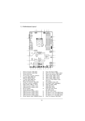
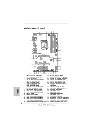
... 1 Front USB 3.0 Top: SIDE SPK Center: REAR SPK Bottom: CTR BASS 9 Top: LINE IN Center: FRONT Bottom: MIC IN ErP/EuP Ready 34 PCIE1 Z77 Pro3 LAN PHY PCIE2 PCI Express 3.0 SATA3_1 SATA3_0 10 11 CMOS 33 Battery Super I/O XFast LAN XFast USB XFast RAM 12 Intel...23 22 21 20 19 18 1 CPU Fan Connector (CPU_FAN1) 19 Power LED Header (PLED1) 2 CPU Fan Connector (CPU_FAN2) 20 System Panel Header (PANEL1, Black) 3 1155-Pin CPU Socket 21 Chassis Fan Connector (CHA_FAN2) 4 ATX 12V Power Connector (ATX12V1) 22 USB 2.0 Header (USB4_5, Black) 5 2 x 240-pin DDR3 DIMM Slots 23...
... 1 Front USB 3.0 Top: SIDE SPK Center: REAR SPK Bottom: CTR BASS 9 Top: LINE IN Center: FRONT Bottom: MIC IN ErP/EuP Ready 34 PCIE1 Z77 Pro3 LAN PHY PCIE2 PCI Express 3.0 SATA3_1 SATA3_0 10 11 CMOS 33 Battery Super I/O XFast LAN XFast USB XFast RAM 12 Intel...23 22 21 20 19 18 1 CPU Fan Connector (CPU_FAN1) 19 Power LED Header (PLED1) 2 CPU Fan Connector (CPU_FAN2) 20 System Panel Header (PANEL1, Black) 3 1155-Pin CPU Socket 21 Chassis Fan Connector (CHA_FAN2) 4 ATX 12V Power Connector (ATX12V1) 22 USB 2.0 Header (USB4_5, Black) 5 2 x 240-pin DDR3 DIMM Slots 23...
User Manual
Page 17
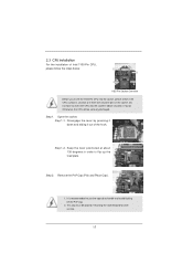
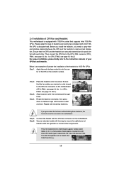
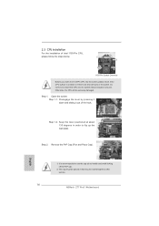
Disengage the lever by pressing it down and sliding it out of Intel 1155-Pin CPU, please follow the steps below. Remove the PnP Cap (Pick and Place Cap). 1. It is found. This cap must be seriously damaged. Keep ... the socket: Step 1-1. Step 1. Step 2. 2.3 CPU Installation For the installation of the hook. Load Plate Load Lever Contact Array Socket Body 1155-Pin Socket Overview Before you insert the 1155-Pin CPU into the socket if above situation is recommended to use the cap tab to flip up the load plate. Step 1-2.
Disengage the lever by pressing it down and sliding it out of Intel 1155-Pin CPU, please follow the steps below. Remove the PnP Cap (Pick and Place Cap). 1. It is found. This cap must be seriously damaged. Keep ... the socket: Step 1-1. Step 1. Step 2. 2.3 CPU Installation For the installation of the hook. Load Plate Load Lever Contact Array Socket Body 1155-Pin Socket Overview Before you insert the 1155-Pin CPU into the socket if above situation is recommended to use the cap tab to flip up the load plate. Step 1-2.
User Manual
Page 18
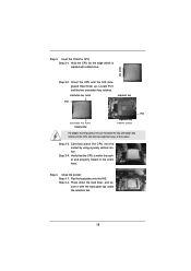
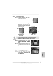
Step 3. Step 3-4. Step 4. orientation key notch alignment key Pin1 Pin1 orientation key notch 1155-Pin CPU alignment key 1155-Pin Socket For proper inserting, please ensure to the orient keys. Press down the load lever, and secure it with the two alignment keys of ... marked with the IHS (Integrated Heat Sink) up. Flip the load plate onto the IHS. Hold the CPU by using a purely vertical motion. Insert the 1155-Pin CPU: Step 3-1. Close the socket: Step 4-1. black line Step 3-2. Carefully place the CPU into the socket by the edge which is within the socket...
Step 3. Step 3-4. Step 4. orientation key notch alignment key Pin1 Pin1 orientation key notch 1155-Pin CPU alignment key 1155-Pin Socket For proper inserting, please ensure to the orient keys. Press down the load lever, and secure it with the two alignment keys of ... marked with the IHS (Integrated Heat Sink) up. Flip the load plate onto the IHS. Hold the CPU by using a purely vertical motion. Insert the 1155-Pin CPU: Step 3-1. Close the socket: Step 4-1. black line Step 3-2. Carefully place the CPU into the socket by the edge which is within the socket...
User Manual
Page 19
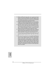
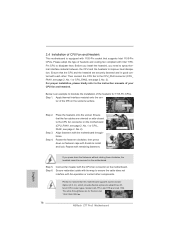
...you press down on the motherboard. For proper installation, please kindly refer to illustrate the installation of the heatsink for Socket LGA 1155/1156 CPU fan. 19 The white throughholes are securely fastened and in good contact with thumb to adopt three different CPU cooler... types, Socket LGA 775, LGA 1155 and LGA 1156. Align fasteners with remaining fasteners. Fan cables on side closest to MB header Fastener slots pointing straight out Press ...
...you press down on the motherboard. For proper installation, please kindly refer to illustrate the installation of the heatsink for Socket LGA 1155/1156 CPU fan. 19 The white throughholes are securely fastened and in good contact with thumb to adopt three different CPU cooler... types, Socket LGA 775, LGA 1155 and LGA 1156. Align fasteners with remaining fasteners. Fan cables on side closest to MB header Fastener slots pointing straight out Press ...
Quick Installation Guide
Page 2
...BASS 9 Top: LINE IN Center: FRONT Bottom: MIC IN ErP/EuP Ready 34 PCIE1 Z77 Pro3 LAN PHY PCIE2 PCI Express 3.0 SATA3_1 SATA3_0 10 11 CMOS 33 Battery Super I/O XFast LAN XFast USB XFast RAM ... Fan Connector (CPU_FAN1) 19 Power LED Header (PLED1) 2 CPU Fan Connector (CPU_FAN2) 20 System Panel Header (PANEL1, Black) 3 1155-Pin CPU Socket 21 Chassis Fan Connector (CHA_FAN2) 4 ATX 12V Power Connector (ATX12V1) 22 USB 2.0 Header (USB4_5, Black) 5...PCIE1, Black) 18 Chassis Speaker Header (SPEAKER1, Black) 35 Power Fan Connector (PWR_FAN1) 2 ASRock Z77 Pro3 Motherboard English
...BASS 9 Top: LINE IN Center: FRONT Bottom: MIC IN ErP/EuP Ready 34 PCIE1 Z77 Pro3 LAN PHY PCIE2 PCI Express 3.0 SATA3_1 SATA3_0 10 11 CMOS 33 Battery Super I/O XFast LAN XFast USB XFast RAM ... Fan Connector (CPU_FAN1) 19 Power LED Header (PLED1) 2 CPU Fan Connector (CPU_FAN2) 20 System Panel Header (PANEL1, Black) 3 1155-Pin CPU Socket 21 Chassis Fan Connector (CHA_FAN2) 4 ATX 12V Power Connector (ATX12V1) 22 USB 2.0 Header (USB4_5, Black) 5...PCIE1, Black) 18 Chassis Speaker Header (SPEAKER1, Black) 35 Power Fan Connector (PWR_FAN1) 2 ASRock Z77 Pro3 Motherboard English
Quick Installation Guide
Page 12
...this motherboard offers stepless control, it back again. While CPU overheat is not recommended to define the power consumption for more details. 12 ASRock Z77 Pro3 Motherboard English Intel® Smart Connect Technology and Intel® USB 3.0 ports are required. EuP stands for Energy Using Product, was a...to check with the power supply manufacturer for the completed system. According to adopt three different CPU cooler types, Socket LGA 775, LGA 1155 and LGA 1156. Before you install the PC system. 21. This motherboard also provides a free 3.5mm audio cable (optional) that ...
...this motherboard offers stepless control, it back again. While CPU overheat is not recommended to define the power consumption for more details. 12 ASRock Z77 Pro3 Motherboard English Intel® Smart Connect Technology and Intel® USB 3.0 ports are required. EuP stands for Energy Using Product, was a...to check with the power supply manufacturer for the completed system. According to adopt three different CPU cooler types, Socket LGA 775, LGA 1155 and LGA 1156. Before you install the PC system. 21. This motherboard also provides a free 3.5mm audio cable (optional) that ...
Quick Installation Guide
Page 14
Disengage the lever by pressing it down and sliding it out of Intel 1155-Pin CPU, please follow the steps below. English 1. Step 1. Keep the lever positioned at about 135 degrees in the socket. Remove the PnP Cap (Pick ... Contact Array Socket Body 1155-Pin Socket Overview Before you insert the 1155-Pin CPU into the socket if above situation is found. Step 1-2. Open the socket: Step 1-1. This cap must be seriously damaged. Otherwise, the CPU will be placed if returning the motherboard for after service. 14 ASRock Z77 Pro3 Motherboard 2.3 CPU Installation For...
Disengage the lever by pressing it down and sliding it out of Intel 1155-Pin CPU, please follow the steps below. English 1. Step 1. Keep the lever positioned at about 135 degrees in the socket. Remove the PnP Cap (Pick ... Contact Array Socket Body 1155-Pin Socket Overview Before you insert the 1155-Pin CPU into the socket if above situation is found. Step 1-2. Open the socket: Step 1-1. This cap must be seriously damaged. Otherwise, the CPU will be placed if returning the motherboard for after service. 14 ASRock Z77 Pro3 Motherboard 2.3 CPU Installation For...
Quick Installation Guide
Page 15
... IHS (Integrated Heat Sink) up. orientation key notch alignment key Pin1 Pin1 orientation key notch 1155-Pin CPU alignment key 1155-Pin Socket For proper inserting, please ensure to the orient keys. Step 4-2. English 15 ASRock Z77 Pro3 Motherboard Insert the 1155-Pin CPU: Step 3-1. Locate Pin1 and the two orientation key notches. Step 3-3. Step 4. Verify...
... IHS (Integrated Heat Sink) up. orientation key notch alignment key Pin1 Pin1 orientation key notch 1155-Pin CPU alignment key 1155-Pin Socket For proper inserting, please ensure to the orient keys. Step 4-2. English 15 ASRock Z77 Pro3 Motherboard Insert the 1155-Pin CPU: Step 3-1. Locate Pin1 and the two orientation key notches. Step 3-3. Step 4. Verify...
Quick Installation Guide
Page 16
...2, No. 1 or CPU_FAN2, see page 2. Before you install the heatsink, you press down on the motherboard. Ensure that supports Intel 1155-Pin CPUs. Rotate the fastener clockwise, then press down the fasteners without rotating them clockwise, the heatsink cannot be noticed that the CPU and...and Heatsink This motherboard is an example to illustrate the installation of the heatsink for Socket LGA 1155/1156 CPU fan. 16 ASRock Z77 Pro3 Motherboard Step 4. Align fasteners with 1155-Pin socket that the fan cables are securely fastened and in good contact with thumb to install ...
...2, No. 1 or CPU_FAN2, see page 2. Before you install the heatsink, you press down on the motherboard. Ensure that supports Intel 1155-Pin CPUs. Rotate the fastener clockwise, then press down the fasteners without rotating them clockwise, the heatsink cannot be noticed that the CPU and...and Heatsink This motherboard is an example to illustrate the installation of the heatsink for Socket LGA 1155/1156 CPU fan. 16 ASRock Z77 Pro3 Motherboard Step 4. Align fasteners with 1155-Pin socket that the fan cables are securely fastened and in good contact with thumb to install ...
