User Manual
Page 14
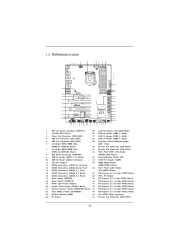
... LAN PCIE2 LAN PHY PCIE3 USB3_11_12 USB3_9_10 Super I/O PCIE4 Z77 Extreme9 XFast RAM PCIE5 MINI_PCIE1 PCIE6 WiFi+BT Module CMOS Battery AUDIO CODEC RoHS HDMI_SPDIF1 1 1 HD_AUDIO1 IR1 COM1 1 1 PCIE7 FRONT_1394 CHA_FAN1 CHA_FAN2 1 USB6_7 1 1 CIR1 USB4_5 1 Intel Z77 RSTBTN Front USB 3.0 USB2_3 1 Dr. Debug CLRCMOS1 PLED1... 30 29 28 27 26 25 24 23 22 21 1 ATX 12V Power Connector (ATX12V1) 25 mini-PCI Express Slot (MINI_PCIE1) 2 1155-Pin CPU Socket 26 USB 2.0 Header (USB2_3, Black) 3 Power Fan Connector (PWR_FAN1) 27 USB 2.0 Header (USB4_5, Black) 4 CPU Fan Connector ...
... LAN PCIE2 LAN PHY PCIE3 USB3_11_12 USB3_9_10 Super I/O PCIE4 Z77 Extreme9 XFast RAM PCIE5 MINI_PCIE1 PCIE6 WiFi+BT Module CMOS Battery AUDIO CODEC RoHS HDMI_SPDIF1 1 1 HD_AUDIO1 IR1 COM1 1 1 PCIE7 FRONT_1394 CHA_FAN1 CHA_FAN2 1 USB6_7 1 1 CIR1 USB4_5 1 Intel Z77 RSTBTN Front USB 3.0 USB2_3 1 Dr. Debug CLRCMOS1 PLED1... 30 29 28 27 26 25 24 23 22 21 1 ATX 12V Power Connector (ATX12V1) 25 mini-PCI Express Slot (MINI_PCIE1) 2 1155-Pin CPU Socket 26 USB 2.0 Header (USB2_3, Black) 3 Power Fan Connector (PWR_FAN1) 27 USB 2.0 Header (USB4_5, Black) 4 CPU Fan Connector ...
User Manual
Page 20
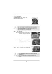
... 1. Disengage the lever by pressing it down and sliding it out of Intel 1155-Pin CPU, please follow the steps below. This cap must be seriously damaged. It is recommended to use the cap tab to insert the CPU into the socket, please check if the CPU surface is found. Step 2. Step 1-2....handle and avoid kicking off the PnP cap. 2. Open the socket: Step 1-1. Remove the PnP Cap (Pick and Place Cap). 1. Load Plate Load Lever Contact Array Socket Body 1155-Pin Socket Overview Before you insert the 1155-Pin CPU into the socket if above situation is unclean or if there are any bent pins...
... 1. Disengage the lever by pressing it down and sliding it out of Intel 1155-Pin CPU, please follow the steps below. This cap must be seriously damaged. It is recommended to use the cap tab to insert the CPU into the socket, please check if the CPU surface is found. Step 2. Step 1-2....handle and avoid kicking off the PnP cap. 2. Open the socket: Step 1-1. Remove the PnP Cap (Pick and Place Cap). 1. Load Plate Load Lever Contact Array Socket Body 1155-Pin Socket Overview Before you insert the 1155-Pin CPU into the socket if above situation is unclean or if there are any bent pins...
User Manual
Page 22
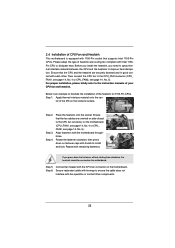
... Step 1. ter of heatsink and cooling fan compliant with tie-wrap to illustrate the installation of the heatsink for 1155-Pin CPUs. Step 3. Repeat with 1155-Pin socket that supports Intel 1155-Pin CPUs. Step 6. Please adopt the type of the IHS on side closest to dissipate heat. Then connect ...the CPU fan to install and lock. Ensure that the CPU and the heatsink are oriented on the socket's surface. Rotate the ...
... Step 1. ter of heatsink and cooling fan compliant with tie-wrap to illustrate the installation of the heatsink for 1155-Pin CPUs. Step 3. Repeat with 1155-Pin socket that supports Intel 1155-Pin CPUs. Step 6. Please adopt the type of the IHS on side closest to dissipate heat. Then connect ...the CPU fan to install and lock. Ensure that the CPU and the heatsink are oriented on the socket's surface. Rotate the ...
Quick Installation Guide
Page 2
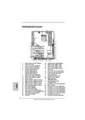
... 27 26 25 24 23 22 21 1 ATX 12V Power Connector (ATX12V1) 25 mini-PCI Express Slot (MINI_PCIE1) 2 1155-Pin CPU Socket 26 USB 2.0 Header (USB2_3, Black) 3 Power Fan Connector (PWR_FAN1) 27 USB 2.0 Header (USB4_5, Black) 4 ..., Black) 33 Infrared Module Header (IR1) 10 USB 3.0 Header (USB3_9_10, Black) 34 COM Port Header (COM1) 11 Intel Z77 Chipset 35 HDMI_SPDIF Header 12 SATA3 Connectors (SATA3_A1_A2, Gray) (HDMI_SPDIF1, Black) 13 SATA3 Connectors (SATA3_A3_A4, Gray) 36 Front ... Connector 24 Dr. Debug 46 Chassis Fan Connector (CHA_FAN3) English 2 ASRock Z77 Extreme9 Motherboard
... 27 26 25 24 23 22 21 1 ATX 12V Power Connector (ATX12V1) 25 mini-PCI Express Slot (MINI_PCIE1) 2 1155-Pin CPU Socket 26 USB 2.0 Header (USB2_3, Black) 3 Power Fan Connector (PWR_FAN1) 27 USB 2.0 Header (USB4_5, Black) 4 ..., Black) 33 Infrared Module Header (IR1) 10 USB 3.0 Header (USB3_9_10, Black) 34 COM Port Header (COM1) 11 Intel Z77 Chipset 35 HDMI_SPDIF Header 12 SATA3 Connectors (SATA3_A1_A2, Gray) (HDMI_SPDIF1, Black) 13 SATA3 Connectors (SATA3_A3_A4, Gray) 36 Front ... Connector 24 Dr. Debug 46 Chassis Fan Connector (CHA_FAN3) English 2 ASRock Z77 Extreme9 Motherboard
Quick Installation Guide
Page 17
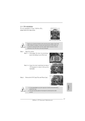
... for after service. 17 ASRock Z77 Extreme9 Motherboard Open the socket: Step 1-1. Keep the lever positioned at about 135 degrees in the socket. Step 1-2. Load Plate Load Lever Contact Array Socket Body 1155-Pin Socket Overview Before you insert the 1155-Pin CPU into the socket, please check if the ...socket if above situation is recommended to use the cap tab to handle and avoid kicking off the PnP cap. 2. Do not force to flip up the load plate. 2.3 CPU Installation For the installation of the hook. Disengage the lever by pressing it down and sliding it out of Intel 1155...
... for after service. 17 ASRock Z77 Extreme9 Motherboard Open the socket: Step 1-1. Keep the lever positioned at about 135 degrees in the socket. Step 1-2. Load Plate Load Lever Contact Array Socket Body 1155-Pin Socket Overview Before you insert the 1155-Pin CPU into the socket, please check if the ...socket if above situation is recommended to use the cap tab to handle and avoid kicking off the PnP cap. 2. Do not force to flip up the load plate. 2.3 CPU Installation For the installation of the hook. Disengage the lever by pressing it down and sliding it out of Intel 1155...
Quick Installation Guide
Page 19
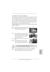
... heatsink and cooling fan compliant with fan operation or contact other . Ensure that supports Intel 1155-Pin CPUs. Step 4. Step 3. Place the heatsink onto the socket. Align fasteners with each other components. Fan cables on the motherboard. English 19 ASRock Z77 Extreme9 Motherboard Below is equipped with thumb to install and lock. Apply Thermal Interface Material...
... heatsink and cooling fan compliant with fan operation or contact other . Ensure that supports Intel 1155-Pin CPUs. Step 4. Step 3. Place the heatsink onto the socket. Align fasteners with each other components. Fan cables on the motherboard. English 19 ASRock Z77 Extreme9 Motherboard Below is equipped with thumb to install and lock. Apply Thermal Interface Material...


