
Intel Rapid Storage Guide
Page 12
..., press Ctrl and i at the same time to enter the option ROM user interface. 2. Enable RAID in System BIOS Use the instructions included with your motherboard to enable RAID in the system BIOS, a RAID volume must be created, and the F6 installation method must be enabled in the system BIOS. 1. Switch...
..., press Ctrl and i at the same time to enter the option ROM user interface. 2. Enable RAID in System BIOS Use the instructions included with your motherboard to enable RAID in the system BIOS, a RAID volume must be created, and the F6 installation method must be enabled in the system BIOS. 1. Switch...

Intel Smart Response Installation Guide
Page 1
... point! 3. Boot system to [RAID Mode]. For the new version RST driver, please check our website for the latest information: http://www.asrock.com * Before you intend to show the newly accelerated system configuration. * Intel® will refresh to accelerate AND the SSD in the near...Maximized" mode. 7. Once open RST GUI from either Start Menu or by step instructions below. Intel Smart Response Technology Installation Guide This motherboard supports Intel Smart Response Technology. You can find the UI setup instruction and the step by double-clicking RST Storage icon in RAID ROM....
... point! 3. Boot system to [RAID Mode]. For the new version RST driver, please check our website for the latest information: http://www.asrock.com * Before you intend to show the newly accelerated system configuration. * Intel® will refresh to accelerate AND the SSD in the near...Maximized" mode. 7. Once open RST GUI from either Start Menu or by step instructions below. Intel Smart Response Technology Installation Guide This motherboard supports Intel Smart Response Technology. You can find the UI setup instruction and the step by double-clicking RST Storage icon in RAID ROM....
User Manual
Page 2
...documentation by the California Legislature. Products and corporate names appearing in this manual may or may be constructed as a commitment by ASRock. In no responsibility for backup purpose, without intent to the following two conditions: (1) this device may not cause harmful interference..., and (2) this device must accept any defect or error in advance. "Perchlorate Material-special handling may appear in this motherboard contains Perchlorate, a toxic substance controlled in Perchlorate Best Management Practices (BMP) regulations passed by the purchaser for any errors ...
...documentation by the California Legislature. Products and corporate names appearing in this manual may or may be constructed as a commitment by ASRock. In no responsibility for backup purpose, without intent to the following two conditions: (1) this device may not cause harmful interference..., and (2) this device must accept any defect or error in advance. "Perchlorate Material-special handling may appear in this motherboard contains Perchlorate, a toxic substance controlled in Perchlorate Best Management Practices (BMP) regulations passed by the purchaser for any errors ...
User Manual
Page 3
Contents 1 Introduction 7 1.1 Package Contents 7 1.2 Specifications 8 1.3 Unique Features 10 1.4 Motherboard Layout 15 1.5 I/O Panel 16 2 Installation 18 2.1 Screw Holes 18 2.2 Pre-installation Precautions 18 2.3 CPU Installation 19 2.4 Installation of Heatsink ...SLITM and Quad SLITM Operation Guide 26 2.8 CrossFireXTM, 3-Way CrossFireXTM and Quad CrossFireXTM Operation Guide 30 2.9 Dual Monitor and Surround Display Features 35 2.10 ASRock Smart Remote Installation Guide 38 2.11 Jumpers Setup 40 2.12 Onboard Headers and Connectors 41 2.13 Serial ATA (SATA) / Serial ATA2 (SATA2) ...
Contents 1 Introduction 7 1.1 Package Contents 7 1.2 Specifications 8 1.3 Unique Features 10 1.4 Motherboard Layout 15 1.5 I/O Panel 16 2 Installation 18 2.1 Screw Holes 18 2.2 Pre-installation Precautions 18 2.3 CPU Installation 19 2.4 Installation of Heatsink ...SLITM and Quad SLITM Operation Guide 26 2.8 CrossFireXTM, 3-Way CrossFireXTM and Quad CrossFireXTM Operation Guide 30 2.9 Dual Monitor and Surround Display Features 35 2.10 ASRock Smart Remote Installation Guide 38 2.11 Jumpers Setup 40 2.12 Onboard Headers and Connectors 41 2.13 Serial ATA (SATA) / Serial ATA2 (SATA2) ...

User Manual
Page 5
You may find the latest VGA cards and CPU support lists on ASRock website without notice. www.asrock.com/support/index.asp 1.1 Package Contents ASRock Z77 Extreme3 Motherboard (ATX Form Factor: 12.0-in x 8.6-in Storage Configuration to AHCI mode. 5 To get better ... setup and information of the Support CD. In this motherboard, please visit our website for purchasing ASRock Z77 Extreme3 motherboard, a reliable motherboard produced under ASRock's consistently stringent quality control. Because the motherboard specifications and the BIOS software might be updated, the content...
You may find the latest VGA cards and CPU support lists on ASRock website without notice. www.asrock.com/support/index.asp 1.1 Package Contents ASRock Z77 Extreme3 Motherboard (ATX Form Factor: 12.0-in x 8.6-in Storage Configuration to AHCI mode. 5 To get better ... setup and information of the Support CD. In this motherboard, please visit our website for purchasing ASRock Z77 Extreme3 motherboard, a reliable motherboard produced under ASRock's consistently stringent quality control. Because the motherboard specifications and the BIOS software might be updated, the content...
User Manual
Page 11
...keep in games. Traffic Shaping: You can boost USB storage device performance. ASRock XFast USB ASRock XFast USB can watch Youtube HD videos and download simultaneously. The performance may depend on -the-go. ASRock APP Charger If you desire a faster, less restricted way of charging your ... window, you can configure your real-time newsfeed into Standby mode (S1), Suspend to 40% faster than before. ASRock motherboards are transferring currently. 11 ASRock XFast LAN ASRock XFast LAN provides a faster internet access, which data streams you can lower the latency in touch with the...
...keep in games. Traffic Shaping: You can boost USB storage device performance. ASRock XFast USB ASRock XFast USB can watch Youtube HD videos and download simultaneously. The performance may depend on -the-go. ASRock APP Charger If you desire a faster, less restricted way of charging your ... window, you can configure your real-time newsfeed into Standby mode (S1), Suspend to 40% faster than before. ASRock motherboards are transferring currently. 11 ASRock XFast LAN ASRock XFast LAN provides a faster internet access, which data streams you can lower the latency in touch with the...

User Manual
Page 13
... Fan can be supported only with processors which virtualizes integrated GPU and discrete GPU for no-compromise visual quality. Please be used. 13 ASRock Dehumidifier Function Users may prevent motherboard damages due to dampness by intelligently reducing redundant rendering tasks in ACPI S5 mode)! The unprecedented UEFI provides a more attractive interface and...
... Fan can be supported only with processors which virtualizes integrated GPU and discrete GPU for no-compromise visual quality. Please be used. 13 ASRock Dehumidifier Function Users may prevent motherboard damages due to dampness by intelligently reducing redundant rendering tasks in ACPI S5 mode)! The unprecedented UEFI provides a more attractive interface and...
User Manual
Page 15
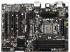
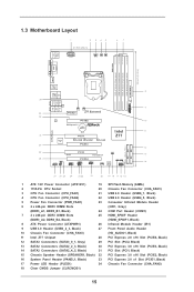
1.3 Motherboard Layout 1 2 3 45 21.8cm (8.6 in) ATX12V1 CPU_FAN1 CPU_FAN2 PWR_FAN1 6 7 USB 2.0 T: USB0 B:...Top: LINE IN Center: Bottom: MIC IN CHA_FAN2 CHA_FAN3 33 PCIE1 Z77 Extreme3 32 AUDIO CODEC PCIE2 10 PCI Express 3.0 CMOS Battery Intel 11 ErP/EuP Ready 31 PCI1 Z77 Super I/O X X X Fast USB Fast RAM Fast LAN 30 ...9 USB 3.0 Header (USB3_2_3, Black) 27 Front Panel Audio Header 10 Chassis Fan Connector (CHA_FAN3) (HD_AUDIO1, Black) 11 Intel Z77 Chipset 28 PCI Express 2.0 x16 Slot (PCIE4, Black) 12 SATA3 Connectors (SATA3_0_1, Gray) 29 PCI Slot (PCI2, Black)...
1.3 Motherboard Layout 1 2 3 45 21.8cm (8.6 in) ATX12V1 CPU_FAN1 CPU_FAN2 PWR_FAN1 6 7 USB 2.0 T: USB0 B:...Top: LINE IN Center: Bottom: MIC IN CHA_FAN2 CHA_FAN3 33 PCIE1 Z77 Extreme3 32 AUDIO CODEC PCIE2 10 PCI Express 3.0 CMOS Battery Intel 11 ErP/EuP Ready 31 PCI1 Z77 Super I/O X X X Fast USB Fast RAM Fast LAN 30 ...9 USB 3.0 Header (USB3_2_3, Black) 27 Front Panel Audio Header 10 Chassis Fan Connector (CHA_FAN3) (HD_AUDIO1, Black) 11 Intel Z77 Chipset 28 PCI Express 2.0 x16 Slot (PCIE4, Black) 12 SATA3 Connectors (SATA3_0_1, Gray) 29 PCI Slot (PCI2, Black)...
User Manual
Page 18
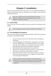
... so may cause severe damage to use a grounded wrist strap or touch a safety grounded object before installing or removing the motherboard. To avoid damaging the motherboard's components due to static electricity, NEVER place your chassis to ensure that the power is switched off or the power cord ...is an ATX form factor (12.0" x 8.6", 30.5 x 21.8 cm) motherboard. Before you uninstall any component, ensure that the motherboard fits into the screw holes to the chassis. When placing screws into it on the carpet or the like. static pad...
... so may cause severe damage to use a grounded wrist strap or touch a safety grounded object before installing or removing the motherboard. To avoid damaging the motherboard's components due to static electricity, NEVER place your chassis to ensure that the power is switched off or the power cord ...is an ATX form factor (12.0" x 8.6", 30.5 x 21.8 cm) motherboard. Before you uninstall any component, ensure that the motherboard fits into the screw holes to the chassis. When placing screws into it on the carpet or the like. static pad...
User Manual
Page 20
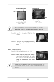
Step 3-2. Please save and replace the cover if the processor is within the socket and properly mated to return the motherboard for after service. 20 The cover must be placed if you wish to the orient keys. Step 2-3. Step 2-4. The protection cover will automatically come off ...
Step 3-2. Please save and replace the cover if the processor is within the socket and properly mated to return the motherboard for after service. 20 The cover must be placed if you wish to the orient keys. Step 2-3. Step 2-4. The protection cover will automatically come off ...

User Manual
Page 21
... see page 15, No. 3 or CPU_FAN2, see page 15. No. 4). Repeat with fan operation or contact other . Please be secured on the motherboard (CPU_FAN1, see page 15, No. 3 or CPU_ FAN2, see page 15. Please adopt the type of heatsink and cooling fan compliant with thumb to ... fan and heatsink. Fan cables on fastener caps with Intel 1155Pin CPU to dissipate heat. Below is equipped with 1155-Pin socket that this motherboard supports Combo Cooler Option (C.C.O.), which provides flexible options to adopt three different CPU cooler types, Socket LGA 775, LGA 1155 and LGA 1156....
... see page 15, No. 3 or CPU_FAN2, see page 15. No. 4). Repeat with fan operation or contact other . Please be secured on the motherboard (CPU_FAN1, see page 15, No. 3 or CPU_ FAN2, see page 15. Please adopt the type of heatsink and cooling fan compliant with thumb to ... fan and heatsink. Fan cables on fastener caps with Intel 1155Pin CPU to dissipate heat. Below is equipped with 1155-Pin socket that this motherboard supports Combo Cooler Option (C.C.O.), which provides flexible options to adopt three different CPU cooler types, Socket LGA 775, LGA 1155 and LGA 1156....
User Manual
Page 22
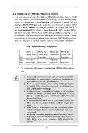
... Configuration Table below. Black slots; see p.15 No. 6) or identical DDR3 DIMMs in all four slots. Populated - otherwise, this motherboard and DIMM may refer to activate Dual Channel Memory Technology. 4. For dual channel configuration, you to install four DDR3 DIMMs for dual ..., please install identical DDR3 DIMMs in the same Dual Channel, for optimal compatibility and reliability, it is unable to install them on this motherboard. Black slots; Dual Channel Memory Configuration DDR3_A1 DDR3_A2 DDR3_B1 DDR3_B2 (Black Slot) (Black Slot) (Black Slot) (Black Slot) (1) -...
... Configuration Table below. Black slots; see p.15 No. 6) or identical DDR3 DIMMs in all four slots. Populated - otherwise, this motherboard and DIMM may refer to activate Dual Channel Memory Technology. 4. For dual channel configuration, you to install four DDR3 DIMMs for dual ..., please install identical DDR3 DIMMs in the same Dual Channel, for optimal compatibility and reliability, it is unable to install them on this motherboard. Black slots; Dual Channel Memory Configuration DDR3_A1 DDR3_A2 DDR3_B1 DDR3_B2 (Black Slot) (Black Slot) (Black Slot) (Black Slot) (1) -...

User Manual
Page 23
... adding or removing DIMMs or the system components. Step 3. Unlock a DIMM slot by pressing the retaining clips outward. Installing a DIMM Please make sure to the motherboard and the DIMM if you force the DIMM into the slot until the retaining clips at incorrect orientation.
... adding or removing DIMMs or the system components. Step 3. Unlock a DIMM slot by pressing the retaining clips outward. Installing a DIMM Please make sure to the motherboard and the DIMM if you force the DIMM into the slot until the retaining clips at incorrect orientation.
User Manual
Page 24
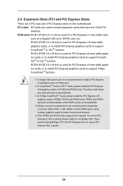
...:PCIE1 (PCIE 2.0 x1 slot) is recommended to install expansion cards that have the 32-bit PCI interface. Please connect a chassis fan to the motherboard's chassis fan connector (CHA_FAN1, CHA_FAN2 or CHA_FAN3) when using multiple graphics cards for PCI Express x16 lane width graphics cards, or to install PCI ... a PCI Express x16 graphics card on PCIE2 slot. 2. In CrossFireXTM mode or SLITM mode, please install the PCI Express x16 graphics cards on this motherboard. Only PCIE2 and PCIE3 slots support Gen 3 speed. To run only at PCI Express Gen 2 speed. 24 In single VGA card mode, it...
...:PCIE1 (PCIE 2.0 x1 slot) is recommended to install expansion cards that have the 32-bit PCI interface. Please connect a chassis fan to the motherboard's chassis fan connector (CHA_FAN1, CHA_FAN2 or CHA_FAN3) when using multiple graphics cards for PCI Express x16 lane width graphics cards, or to install PCI ... a PCI Express x16 graphics card on PCIE2 slot. 2. In CrossFireXTM mode or SLITM mode, please install the PCI Express x16 graphics cards on this motherboard. Only PCIE2 and PCIE3 slots support Gen 3 speed. To run only at PCI Express Gen 2 speed. 24 In single VGA card mode, it...

User Manual
Page 25
... installing an expansion card, please make necessary hardware settings for later use . Step 4. Replace the system cover. 25 Remove the system unit cover (if your motherboard is unplugged. Step 2. Keep the screws for the card before you intend to the chassis with the slot and press firmly until the card is...
... installing an expansion card, please make necessary hardware settings for later use . Step 4. Replace the system cover. 25 Remove the system unit cover (if your motherboard is unplugged. Step 2. Keep the screws for the card before you intend to the chassis with the slot and press firmly until the card is...

User Manual
Page 26
... two identical PCI Express x16 graphics cards. Download the driver from NVIDIA® website (www.nvidia.com). 3. Step2. 2.7 SLITM and Quad SLITM Operation Guide This motherboard supports NVIDIA® SLITM and Quad SLITM (Scalable Link Interface) technology that your system. Make sure that allows you should have two identical SLITM-ready...
... two identical PCI Express x16 graphics cards. Download the driver from NVIDIA® website (www.nvidia.com). 3. Step2. 2.7 SLITM and Quad SLITM Operation Guide This motherboard supports NVIDIA® SLITM and Quad SLITM (Scalable Link Interface) technology that your system. Make sure that allows you should have two identical SLITM-ready...

User Manual
Page 30
...and image quality in the future, please refer to PCIE3 slot. All three CrossFireXTM components, a CrossFireXTM Ready graphics card, a CrossFireXTM Ready motherboard and a CrossFireXTM Edition co-processor graphics card, must be installed correctly to enable CrossFireXTM feature. Insert one Radeon graphics card into PCIE2 ...technology offers the most advantageous means available of CrossFireXTM. Step 1. 2.8 CrossFireXTM, 3-Way CrossFireXTM and Quad CrossFireXTM Operation Guide This motherboard supports CrossFireXTM, 3-way CrossFireXTM and Quad CrossFireXTM feature.
...and image quality in the future, please refer to PCIE3 slot. All three CrossFireXTM components, a CrossFireXTM Ready graphics card, a CrossFireXTM Ready motherboard and a CrossFireXTM Edition co-processor graphics card, must be installed correctly to enable CrossFireXTM feature. Insert one Radeon graphics card into PCIE2 ...technology offers the most advantageous means available of CrossFireXTM. Step 1. 2.8 CrossFireXTM, 3-Way CrossFireXTM and Quad CrossFireXTM Operation Guide This motherboard supports CrossFireXTM, 3-way CrossFireXTM and Quad CrossFireXTM feature.

User Manual
Page 31
... the Radeon graphics card on the top of Radeon graphics cards. (CrossFire Bridge is provided with the graphics card you purchase, not bundled with this motherboard. Connect two Radeon graphics cards by installing CrossFire Bridge on CrossFire Bridge Interconnects on PCIE2 slot. (You may use the DVI to D-Sub adapter to...
... the Radeon graphics card on the top of Radeon graphics cards. (CrossFire Bridge is provided with the graphics card you purchase, not bundled with this motherboard. Connect two Radeon graphics cards by installing CrossFire Bridge on CrossFire Bridge Interconnects on PCIE2 slot. (You may use the DVI to D-Sub adapter to...

User Manual
Page 32
.... Make sure that are properly seated on PCIE3 and PCIE4 slots. (CrossFireTM Bridge is provided with the graphics card you purchase, not bundled with this motherboard. Use one graphics card into PCIE2 slot, another graphics card to PCIE3 slot, and the other CrossFireTM Bridge to D-Sub adapter.) 32 Step 2. 2.8.1.2 Installing Three...
.... Make sure that are properly seated on PCIE3 and PCIE4 slots. (CrossFireTM Bridge is provided with the graphics card you purchase, not bundled with this motherboard. Use one graphics card into PCIE2 slot, another graphics card to PCIE3 slot, and the other CrossFireTM Bridge to D-Sub adapter.) 32 Step 2. 2.8.1.2 Installing Three...
User Manual
Page 35
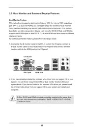
2.9 Dual Monitor and Surround Display Features Dual Monitor Feature This motherboard supports dual monitor feature. Connect a DVI-D monitor cable to the DVI-D port on the I/O panel, connect a D-Sub monitor cable to the D-Sub port on the I/O ...-D and HDMI monitors cannot be enabled at the same time. You can drive same or different display contents. This motherboard also provides independent display controllers for DVI-D, D-Sub and HDMI to this motherboard. If you haven't installed the onboard VGA driver yet, please install the onboard VGA driver from our support CD...
2.9 Dual Monitor and Surround Display Features Dual Monitor Feature This motherboard supports dual monitor feature. Connect a DVI-D monitor cable to the DVI-D port on the I/O panel, connect a D-Sub monitor cable to the D-Sub port on the I/O ...-D and HDMI monitors cannot be enabled at the same time. You can drive same or different display contents. This motherboard also provides independent display controllers for DVI-D, D-Sub and HDMI to this motherboard. If you haven't installed the onboard VGA driver yet, please install the onboard VGA driver from our support CD...

