User Manual
Page 5
... option in , 30.5 cm x 24.4 cm) ASRock Z68 Extreme7 Gen3 Quick Installation Guide ASRock Z68 Extreme7 Gen3 Support CD 6 x Serial ATA (SATA) Data Cables (Optional) 2 x Serial ATA (SATA) HDD Power Cables (Optional) 1 x 3.5mm Audio Cable (Optional) 1 x I/O Panel Shield 1 x Front USB 3.0 Panel 4 x HDD Screws 6 x Chassis Screws 1 x Rear USB 3.0 Bracket 1 x ASRock SLI_Bridge_2S Card 1 x ASRock 3-Way SLI-2S2S Bridge Card 1 x PS/2 Mouse/Keyboard + USB...
... option in , 30.5 cm x 24.4 cm) ASRock Z68 Extreme7 Gen3 Quick Installation Guide ASRock Z68 Extreme7 Gen3 Support CD 6 x Serial ATA (SATA) Data Cables (Optional) 2 x Serial ATA (SATA) HDD Power Cables (Optional) 1 x 3.5mm Audio Cable (Optional) 1 x I/O Panel Shield 1 x Front USB 3.0 Panel 4 x HDD Screws 6 x Chassis Screws 1 x Rear USB 3.0 Bracket 1 x ASRock SLI_Bridge_2S Card 1 x ASRock 3-Way SLI-2S2S Bridge Card 1 x PS/2 Mouse/Keyboard + USB...
User Manual
Page 8
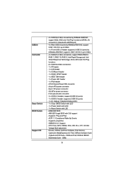
SLI/XFire power connector - AMI UEFI Legal BIOS with eSATA3 port) - 4 x Rear USB 3.0 ports by ASMedia ASM1042, support USB 1.0/2.0/3.0 up to 5Gb/s - 1 x ... - 1 x CIR header - 1 x COM port header - 1 x HDMI_SPDIF header - 1 x IEEE 1394 header - 1 x Power LED header - 1 x PS2 header - ASRock MAGIX Multimedia Suite - Supports jumperfree - Drivers, Utilities, AntiVirus Software (Trial Version), CyberLink MediaEspresso 6.5 Trial, ASRock Software Suite (CyberLink DVD Suite - ACPI 1.1 Compliance Wake Up Events - SMBIOS 2.3.1 Support - USB3.0 Connector Smart Switch BIOS Feature...
SLI/XFire power connector - AMI UEFI Legal BIOS with eSATA3 port) - 4 x Rear USB 3.0 ports by ASMedia ASM1042, support USB 1.0/2.0/3.0 up to 5Gb/s - 1 x ... - 1 x CIR header - 1 x COM port header - 1 x HDMI_SPDIF header - 1 x IEEE 1394 header - 1 x Power LED header - 1 x PS2 header - ASRock MAGIX Multimedia Suite - Supports jumperfree - Drivers, Utilities, AntiVirus Software (Trial Version), CyberLink MediaEspresso 6.5 Trial, ASRock Software Suite (CyberLink DVD Suite - ACPI 1.1 Compliance Wake Up Events - SMBIOS 2.3.1 Support - USB3.0 Connector Smart Switch BIOS Feature...
User Manual
Page 13
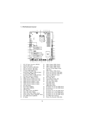
... USB 3.0 T: USB3 Top: B: USB4 RJ-45 Top: Central/Bass LINE IN Center: REAR SPK Top: Center: FRONT LAN PHY RoHS Super I/O SLI/XFIRE_PWR1 CHA_FAN3 PCIE1 Z68 Extreme7 Gen3 PCIE2 PCIE3 XFast USB PCIE4 3-Way SLI PCI1 SATA3 6Gb/s ErP/EuP Ready Front USB 3.0 PCIE5 AUDIO CODEC PCI Express 3.0 HD_AUDIO1 1 1 IR1 HDMI_SPDIF1 1 1 COM1 PS2_1 1 PCIE6 FRONT_1394...
... USB 3.0 T: USB3 Top: B: USB4 RJ-45 Top: Central/Bass LINE IN Center: REAR SPK Top: Center: FRONT LAN PHY RoHS Super I/O SLI/XFIRE_PWR1 CHA_FAN3 PCIE1 Z68 Extreme7 Gen3 PCIE2 PCIE3 XFast USB PCIE4 3-Way SLI PCI1 SATA3 6Gb/s ErP/EuP Ready Front USB 3.0 PCIE5 AUDIO CODEC PCI Express 3.0 HD_AUDIO1 1 1 IR1 HDMI_SPDIF1 1 1 COM1 PS2_1 1 PCIE6 FRONT_1394...

User Manual
Page 26
... on the PCI Express graphics card are connected. Step3. Make sure that are properly seated on the three graphics cards. Make sure ASRock 3-Way SLI-2S2S Bridge Card is inserted to PCIE1 slot. 26 Please make sure that is firmly in place. Align and insert...Bridge Card to the PCI Express graphics card. Connect a VGA cable or a DVI cable to PCIE6 slot. Repeat this step on the slots. ASRock 3-Way SLI-2S2S Bridge Card Step4. 2.7.1.2 Installing Three SLITM-Ready Graphics Cards Step 1. Insert one graphics card into PCIE1 slot, another graphics card to PCIE4 slot...
... on the PCI Express graphics card are connected. Step3. Make sure that are properly seated on the three graphics cards. Make sure ASRock 3-Way SLI-2S2S Bridge Card is inserted to PCIE1 slot. 26 Please make sure that is firmly in place. Align and insert...Bridge Card to the PCI Express graphics card. Connect a VGA cable or a DVI cable to PCIE6 slot. Repeat this step on the slots. ASRock 3-Way SLI-2S2S Bridge Card Step4. 2.7.1.2 Installing Three SLITM-Ready Graphics Cards Step 1. Insert one graphics card into PCIE1 slot, another graphics card to PCIE4 slot...
User Manual
Page 27
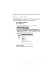
... follow the below procedures to your system. And click Apply. D. Double-click NVIDIA Settings icon on your system. B. From the pop-up menu, select Set SLI and PhysX configuration. Reboot your Windows® taskbar. You can enable the MultiGraphics Processing Unit (GPU) feature in the NVIDIA® nView system...
... follow the below procedures to your system. And click Apply. D. Double-click NVIDIA Settings icon on your system. B. From the pop-up menu, select Set SLI and PhysX configuration. Reboot your Windows® taskbar. You can enable the MultiGraphics Processing Unit (GPU) feature in the NVIDIA® nView system...

User Manual
Page 28
... PhysX configuration. Select Control Panel tab. In Select an SLI configuration item, please select Enable SLI. Reboot your Windows taskbar. You can freely enjoy the benefit of SLITM or Quad SLITM feature. 28 D. B. E. G. From the pop-up menu, select All ...
... PhysX configuration. Select Control Panel tab. In Select an SLI configuration item, please select Enable SLI. Reboot your Windows taskbar. You can freely enjoy the benefit of SLITM or Quad SLITM feature. 28 D. B. E. G. From the pop-up menu, select All ...

User Manual
Page 29
... / VistaTM 64-bit / 7 / 7 64-bit OS: (For 3-Way SLITM mode) A. C. From the pop-up menu, select Set SLI and PhysX configuration. B. In Select an SLI configuration item, please select Enable 3-way SLI. D. In Select a hardware acceleration setting for identification or explanation and to the owners' benefi...
... / VistaTM 64-bit / 7 / 7 64-bit OS: (For 3-Way SLITM mode) A. C. From the pop-up menu, select Set SLI and PhysX configuration. B. In Select an SLI configuration item, please select Enable 3-way SLI. D. In Select a hardware acceleration setting for identification or explanation and to the owners' benefi...

User Manual
Page 46
...-pin ATX power supply, please plug your power supply along with Pin 1 and Pin 5. 8 5 4-Pin ATX 12V Power Supply Installation 4 1 SLI/XFIRE Power Connector (4-pin SLI/XFIRE_PWR1) (see p.13 No. 45) SLI/XFIRE_POWER1 It is not necessary to use the 4-pin ATX power supply, please plug your power supply along with a hard disk...
...-pin ATX power supply, please plug your power supply along with Pin 1 and Pin 5. 8 5 4-Pin ATX 12V Power Supply Installation 4 1 SLI/XFIRE Power Connector (4-pin SLI/XFIRE_PWR1) (see p.13 No. 45) SLI/XFIRE_POWER1 It is not necessary to use the 4-pin ATX power supply, please plug your power supply along with a hard disk...
Quick Installation Guide
Page 2
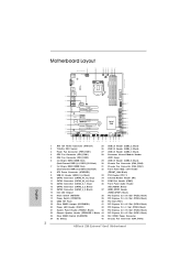
...USB3 Top: B: USB4 RJ-45 Top: Central/Bass LINE IN Center: REAR SPK Top: Center: FRONT LAN PHY RoHS Super I/O SLI/XFIRE_PWR1 CHA_FAN3 PCIE1 Z68 Extreme7 Gen3 PCIE2 PCIE3 XFast USB PCIE4 3-Way SLI PCI1 SATA3 6Gb/s ErP/EuP Ready Front USB 3.0 PCIE5 AUDIO CODEC PCI Express 3.0 HD_AUDIO1 1 1 IR1 HDMI_SPDIF1 1 1 COM1 ..., Black) 22 Chassis Speaker Header (SPEAKER 1, Black) 44 PCI Express 2.0 x16 Slot (PCIE1, Black) 23 Clear CMOS Switch (CLRCBTN) 45 SLI / XFIRE Power Connector 24 Dr. Debug 46 Chassis Fan Connector (CHA_FAN3) 2 ASRock Z68 Extreme7 Gen3 Motherboard English
...USB3 Top: B: USB4 RJ-45 Top: Central/Bass LINE IN Center: REAR SPK Top: Center: FRONT LAN PHY RoHS Super I/O SLI/XFIRE_PWR1 CHA_FAN3 PCIE1 Z68 Extreme7 Gen3 PCIE2 PCIE3 XFast USB PCIE4 3-Way SLI PCI1 SATA3 6Gb/s ErP/EuP Ready Front USB 3.0 PCIE5 AUDIO CODEC PCI Express 3.0 HD_AUDIO1 1 1 IR1 HDMI_SPDIF1 1 1 COM1 ..., Black) 22 Chassis Speaker Header (SPEAKER 1, Black) 44 PCI Express 2.0 x16 Slot (PCIE1, Black) 23 Clear CMOS Switch (CLRCBTN) 45 SLI / XFIRE Power Connector 24 Dr. Debug 46 Chassis Fan Connector (CHA_FAN3) 2 ASRock Z68 Extreme7 Gen3 Motherboard English
Quick Installation Guide
Page 5
... Manual" in , 30.5 cm x 24.4 cm) ASRock Z68 Extreme7 Gen3 Quick Installation Guide ASRock Z68 Extreme7 Gen3 Support CD 6 x Serial ATA (SATA) Data Cables (Optional) 2 x Serial ATA (SATA) HDD Power Cables (Optional) 1 x 3.5mm Audio Cable (Optional) 1 x I/O Panel Shield 1 x Front USB 3.0 Panel 4 x HDD Screws 6 x Chassis Screws 1 x Rear USB 3.0 Bracket 1 x ASRock SLI_Bridge_2S Card 1 x ASRock 3-Way SLI-2S2S Bridge Card 1 x PS/2 Mouse/Keyboard + USB...
... Manual" in , 30.5 cm x 24.4 cm) ASRock Z68 Extreme7 Gen3 Quick Installation Guide ASRock Z68 Extreme7 Gen3 Support CD 6 x Serial ATA (SATA) Data Cables (Optional) 2 x Serial ATA (SATA) HDD Power Cables (Optional) 1 x 3.5mm Audio Cable (Optional) 1 x I/O Panel Shield 1 x Front USB 3.0 Panel 4 x HDD Screws 6 x Chassis Screws 1 x Rear USB 3.0 Bracket 1 x ASRock SLI_Bridge_2S Card 1 x ASRock 3-Way SLI-2S2S Bridge Card 1 x PS/2 Mouse/Keyboard + USB...
Quick Installation Guide
Page 8
SLI/XFire power connector - AMI UEFI Legal BIOS with LED - 64Mb AMI BIOS - Supports "Plug and Play" - SMBIOS 2.3.1 Support - Supports jumperfree - CPU Core, IGPU, DRAM, PCH, CPU PLL, VTT, VCCSA Voltage Multi-adjustment - ASRock MAGIX Multimedia Suite - CPU/Chassis/Power FAN connector - 24 pin ATX power connector - 8 pin 12V power connector - Front panel... header - 1 x CIR header - 1 x COM port header - 1 x HDMI_SPDIF header - 1 x IEEE 1394 header - 1 x Power LED header - 1 x PS2 header - ACPI 1.1 Compliance Wake Up Events - OEM and Trial; OEM) ASRock Z68 Extreme7 Gen3 Motherboard
SLI/XFire power connector - AMI UEFI Legal BIOS with LED - 64Mb AMI BIOS - Supports "Plug and Play" - SMBIOS 2.3.1 Support - Supports jumperfree - CPU Core, IGPU, DRAM, PCH, CPU PLL, VTT, VCCSA Voltage Multi-adjustment - ASRock MAGIX Multimedia Suite - CPU/Chassis/Power FAN connector - 24 pin ATX power connector - 8 pin 12V power connector - Front panel... header - 1 x CIR header - 1 x COM port header - 1 x HDMI_SPDIF header - 1 x IEEE 1394 header - 1 x Power LED header - 1 x PS2 header - ACPI 1.1 Compliance Wake Up Events - OEM and Trial; OEM) ASRock Z68 Extreme7 Gen3 Motherboard

Quick Installation Guide
Page 22
... power source to PCIE6 slot. Make sure that is firmly in place. Step3. Align and insert ASRock 3-Way SLI-2S2S Bridge Card to PCIE1 slot. 22 ASRock Z68 Extreme7 Gen3 Motherboard Make sure ASRock 3-Way SLI-2S2S Bridge Card is inserted to the goldfingers on the three graphics cards. Two Goldfingers...the identical 3-Way SLITM-ready graphics cards that both power connectors on the PCI Express graphics card are properly seated on the slots. English ASRock 3-Way SLI-2S2S Bridge Card Step4. 2.5.1.2 Installing Three SLITM-Ready Graphics Cards Step 1.
... power source to PCIE6 slot. Make sure that is firmly in place. Step3. Align and insert ASRock 3-Way SLI-2S2S Bridge Card to PCIE1 slot. 22 ASRock Z68 Extreme7 Gen3 Motherboard Make sure ASRock 3-Way SLI-2S2S Bridge Card is inserted to the goldfingers on the three graphics cards. Two Goldfingers...the identical 3-Way SLITM-ready graphics cards that both power connectors on the PCI Express graphics card are properly seated on the slots. English ASRock 3-Way SLI-2S2S Bridge Card Step4. 2.5.1.2 Installing Three SLITM-Ready Graphics Cards Step 1.

Quick Installation Guide
Page 23
C. After that, you can freely enjoy the benefit of SLITM feature. 23 ASRock Z68 Extreme7 Gen3 Motherboard English From the pop-up menu, select Set SLI and PhysX configuration. Reboot your Windows® taskbar. Double-click NVIDIA Settings icon on your system. D. ... can enable the MultiGraphics Processing Unit (GPU) feature in the NVIDIA® nView system tray utility. In Select an SLI configuration item, please select Enable SLI. B. And click Apply. In Set PhysX GPU acceleration item, please select Enabled. Please follow the below procedures to ...
C. After that, you can freely enjoy the benefit of SLITM feature. 23 ASRock Z68 Extreme7 Gen3 Motherboard English From the pop-up menu, select Set SLI and PhysX configuration. Reboot your Windows® taskbar. Double-click NVIDIA Settings icon on your system. D. ... can enable the MultiGraphics Processing Unit (GPU) feature in the NVIDIA® nView system tray utility. In Select an SLI configuration item, please select Enable SLI. B. And click Apply. In Set PhysX GPU acceleration item, please select Enabled. Please follow the below procedures to ...

Quick Installation Guide
Page 24
... configuration. E. F. C. In Select an SLI configuration item, please select Enable SLI. And click Apply. From the pop-up menu, select All Programs, and then click NVIDIA Corporation. You can freely enjoy the benefit of SLITM or Quad SLITM feature. 24 ASRock Z68 Extreme7 Gen3 Motherboard English B. Select NVIDIA Control Panel tab...
... configuration. E. F. C. In Select an SLI configuration item, please select Enable SLI. And click Apply. From the pop-up menu, select All Programs, and then click NVIDIA Corporation. You can freely enjoy the benefit of SLITM or Quad SLITM feature. 24 ASRock Z68 Extreme7 Gen3 Motherboard English B. Select NVIDIA Control Panel tab...

Quick Installation Guide
Page 25
.... Follow step A to infringe. 25 ASRock Z68 Extreme7 Gen3 Motherboard English C. Reboot your system. You can freely enjoy the benefit of 3-Way SLITM feature. * SLITM appearing here is a registered trademark of NVIDIA® Technologies Inc., and is used only for PhysX item, please select Enabled. In Select an SLI configuration item, please...
.... Follow step A to infringe. 25 ASRock Z68 Extreme7 Gen3 Motherboard English C. Reboot your system. You can freely enjoy the benefit of 3-Way SLITM feature. * SLITM appearing here is a registered trademark of NVIDIA® Technologies Inc., and is used only for PhysX item, please select Enabled. In Select an SLI configuration item, please...

Quick Installation Guide
Page 42
...to this connector. 1 13 Though this (4-pin SLI/XFIRE_PWR1) connector, but please connect it can still work if you adopt a traditional 20-pin ATX power supply. Though this connector. Though this motherboard. 42 ASRock Z68 Extreme7 Gen3 Motherboard To use the 20-pin ATX power supply..., please plug your power supply along with Pin 1 and Pin 5. 8 5 4-Pin ATX 12V Power Supply Installation 4 1 SLI/XFIRE Power Connector It is not necessary to ...
...to this connector. 1 13 Though this (4-pin SLI/XFIRE_PWR1) connector, but please connect it can still work if you adopt a traditional 20-pin ATX power supply. Though this connector. Though this motherboard. 42 ASRock Z68 Extreme7 Gen3 Motherboard To use the 20-pin ATX power supply..., please plug your power supply along with Pin 1 and Pin 5. 8 5 4-Pin ATX 12V Power Supply Installation 4 1 SLI/XFIRE Power Connector It is not necessary to ...

Quick Installation Guide
Page 191
ASRock Z68 Extreme7 Gen3 CD BIOS VGA CPU サ ASRock http://www.asrock.com Web サイト い。 www.asrock.com/support/index.asp 1.1 ASRock Z68 Extreme7 Gen3 ATX 12.0-in x 9.6-in, 30.5 cm x 24.4 cm) ASRock Z68 Extreme7 Gen3 ASRock Z68 Extreme7 Gen3 CD 6 x ATA (SATA 2 x l ATA (SATA) HDD 1 x 3.5mm 1 x I/O 1 x USB 3.0 4 x HDD ねじ 6 x 1 x 背面USB 3.0 1 x ASRock SLI_Bridge_2S カード 1 x ASRock 3-Way SLI-2S2S Bridge カード...
ASRock Z68 Extreme7 Gen3 CD BIOS VGA CPU サ ASRock http://www.asrock.com Web サイト い。 www.asrock.com/support/index.asp 1.1 ASRock Z68 Extreme7 Gen3 ATX 12.0-in x 9.6-in, 30.5 cm x 24.4 cm) ASRock Z68 Extreme7 Gen3 ASRock Z68 Extreme7 Gen3 CD 6 x ATA (SATA 2 x l ATA (SATA) HDD 1 x 3.5mm 1 x I/O 1 x USB 3.0 4 x HDD ねじ 6 x 1 x 背面USB 3.0 1 x ASRock SLI_Bridge_2S カード 1 x ASRock 3-Way SLI-2S2S Bridge カード...
Quick Installation Guide
Page 209
...; X 9.6 英吋 , 30.5 厘米 X 24.4 厘米 ) 華擎 Z68 Extreme7 Gen3 Z68 Extreme7 Gen3 Serial ATA(SATA Serial ATA(SATA 3.5mm I/O USB 3.0 USB 3.0 SLI_Bridge_2S 3-Way SLI-2S2S PS/2 USB 2.0 ASRock 為了在 Windows® 7 / 7 64-bit / VistaTM / VistaTM 64-bit BIOS中將Storage Configuration AHCI BIOS User Manual 209 ASRock Z68 Extreme7 Gen3 Motherboard 簡體中文
...; X 9.6 英吋 , 30.5 厘米 X 24.4 厘米 ) 華擎 Z68 Extreme7 Gen3 Z68 Extreme7 Gen3 Serial ATA(SATA Serial ATA(SATA 3.5mm I/O USB 3.0 USB 3.0 SLI_Bridge_2S 3-Way SLI-2S2S PS/2 USB 2.0 ASRock 為了在 Windows® 7 / 7 64-bit / VistaTM / VistaTM 64-bit BIOS中將Storage Configuration AHCI BIOS User Manual 209 ASRock Z68 Extreme7 Gen3 Motherboard 簡體中文

Lucid Virtu Installation Guide
Page 3
... power saving i-Mode. If you use d-Mode for demanding 3D gamers to achieve uncompromised 3D performance of IPG DVI output. 3.2 d-Mode d-Mode is equipped with SLI / Crossfire feature, please select d-Mode. 3 Hardware installation 3.1 i-Mode i-Mode provides user with Intel Sandy special features and power saving options when no 3D gaming is...
... power saving i-Mode. If you use d-Mode for demanding 3D gamers to achieve uncompromised 3D performance of IPG DVI output. 3.2 d-Mode d-Mode is equipped with SLI / Crossfire feature, please select d-Mode. 3 Hardware installation 3.1 i-Mode i-Mode provides user with Intel Sandy special features and power saving options when no 3D gaming is...