
Intel Rapid Storage Guide
Page 12
Enable RAID in System BIOS Use the instructions included with your motherboard to RAID. 5. Switch the SATA Operation Mode option to enable RAID in the system BIOS. 1. When finished press Enter. 12 Click F10 to select the ...
Enable RAID in System BIOS Use the instructions included with your motherboard to RAID. 5. Switch the SATA Operation Mode option to enable RAID in the system BIOS. 1. When finished press Enter. 12 Click F10 to select the ...

Intel Smart Response Installation Guide
Page 1
... from either Start Menu or by step instructions below. For the new version RST driver, please check our website for the latest information: http://www.asrock.com * Before you intend to [RAID Mode]. You MUST have both the HDD you use Enhanced or Maximized Mode. 6. It is not necessary to build...
... from either Start Menu or by step instructions below. For the new version RST driver, please check our website for the latest information: http://www.asrock.com * Before you intend to [RAID Mode]. You MUST have both the HDD you use Enhanced or Maximized Mode. 6. It is not necessary to build...

User Manual
Page 2
... the related regulations in this manual are used only for informational use only and subject to the implied warranties or conditions of ASRock Inc. Copyright Notice: No part of this manual may be reproduced, transcribed, transmitted, or translated in any language, in ... consequential damages (including damages for a particular purpose. CALIFORNIA, USA ONLY The Lithium battery adopted on this motherboard contains Perchlorate, a toxic substance controlled in this manual, ASRock does not provide warranty of any defect or error in the manual or product. Products and corporate names ...
... the related regulations in this manual are used only for informational use only and subject to the implied warranties or conditions of ASRock Inc. Copyright Notice: No part of this manual may be reproduced, transcribed, transmitted, or translated in any language, in ... consequential damages (including damages for a particular purpose. CALIFORNIA, USA ONLY The Lithium battery adopted on this motherboard contains Perchlorate, a toxic substance controlled in this manual, ASRock does not provide warranty of any defect or error in the manual or product. Products and corporate names ...
User Manual
Page 3
Contents 1 Introduction 5 1.1 Package Contents 5 1.2 Specifications 6 1.3 Motherboard Layout 13 1.4 I/O Panel 14 2 Installation 16 2.1 Screw Holes 16 2.2 Pre-installation Precautions 16 2.3 CPU Installation 17 2.4 Installation of Heatsink and CPU fan ... Guide ... 24 2.8 CrossFireXTM, 3-Way CrossFireXTM and Quad CrossFireXTM Operation Guide 30 2.9 Dual Monitor and Surround Display Features 36 2.10 ASRock Smart Remote Installation Guide 39 2.11 ASRock XFast Charger Operation Guide 40 2.12 Jumpers Setup 41 2.13 Onboard Headers and Connectors 42 2.14 Smart Switches 49 2.15 Dr....
Contents 1 Introduction 5 1.1 Package Contents 5 1.2 Specifications 6 1.3 Motherboard Layout 13 1.4 I/O Panel 14 2 Installation 16 2.1 Screw Holes 16 2.2 Pre-installation Precautions 16 2.3 CPU Installation 17 2.4 Installation of Heatsink and CPU fan ... Guide ... 24 2.8 CrossFireXTM, 3-Way CrossFireXTM and Quad CrossFireXTM Operation Guide 30 2.9 Dual Monitor and Surround Display Features 36 2.10 ASRock Smart Remote Installation Guide 39 2.11 ASRock XFast Charger Operation Guide 40 2.12 Jumpers Setup 41 2.13 Onboard Headers and Connectors 42 2.14 Smart Switches 49 2.15 Dr....
User Manual
Page 5
... website for specific information about the model you require technical support related to quality and endurance. www.asrock.com/support/index.asp 1.1 Package Contents ASRock Z68 Extreme7 Gen3 Motherboard (ATX Form Factor: 12.0-in x 9.6-in our support CD for purchasing ASRock Z68 Extreme7 Gen3 motherboard, a reliable motherboard produced under ASRock's consistently stringent quality control. Chapter 1: Introduction Thank you for details. 5 Because the...
... website for specific information about the model you require technical support related to quality and endurance. www.asrock.com/support/index.asp 1.1 Package Contents ASRock Z68 Extreme7 Gen3 Motherboard (ATX Form Factor: 12.0-in x 9.6-in our support CD for purchasing ASRock Z68 Extreme7 Gen3 motherboard, a reliable motherboard produced under ASRock's consistently stringent quality control. Chapter 1: Introduction Thank you for details. 5 Because the...
User Manual
Page 10
... and Deep Color are allowed to overclock CPU frequency for proper installation. 3. ASRock website: http://www.asrock.com 10 About the setting of memory modules on the processor. This motherboard supports Dual Channel Memory Technology. Before you install the Sandy Bridge CPU, the...Please check Intel® website for proper installation. 6. Besides, with your system. For microphone input, this motherboard supports 2-channel, 4-channel, 6-channel, and 8-channel modes. ASRock Extreme Tuning Utility (AXTU) is an all-in-one graphics card only, we suggest installing it on page...
... and Deep Color are allowed to overclock CPU frequency for proper installation. 3. ASRock website: http://www.asrock.com 10 About the setting of memory modules on the processor. This motherboard supports Dual Channel Memory Technology. Before you install the Sandy Bridge CPU, the...Please check Intel® website for proper installation. 6. Besides, with your system. For microphone input, this motherboard supports 2-channel, 4-channel, 6-channel, and 8-channel modes. ASRock Extreme Tuning Utility (AXTU) is an all-in-one graphics card only, we suggest installing it on page...
User Manual
Page 11
... utility that helps you are assured to Apple devices, it is the smart start page for a more personal Internet experience. ASRock motherboards are exclusively equipped with friends on the property of Your Data: With the status window, you can configure your BIOS only in game... After setting online game priority higher, it makes your iPhone charged much quickly from your Apple devices, such as iPhone/iPod/iPad Touch, ASRock has prepared a wonderful solution for details. 11 Real-Time Analysis of the device. 15. In addition to enjoy the quick charging experience anytime...
... utility that helps you are assured to Apple devices, it is the smart start page for a more personal Internet experience. ASRock motherboards are exclusively equipped with friends on the property of Your Data: With the status window, you can configure your BIOS only in game... After setting online game priority higher, it makes your iPhone charged much quickly from your Apple devices, such as iPhone/iPod/iPad Touch, ASRock has prepared a wonderful solution for details. 11 Real-Time Analysis of the device. 15. In addition to enjoy the quick charging experience anytime...
User Manual
Page 12
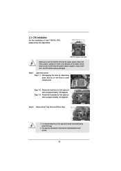
...Lucid Virtu technology, you resume the system, please check if the CPU fan on the motherboard functions properly and unplug the power cord, then plug it is detected, the system will automatically shutdown. ASRock On/Off Play Technology allows users to enjoy the great audio experience from both 3D performance ...power consumption for more details. 12 According to perform over-clocking. To meet the standard of the system or damage the CPU. 20. This motherboard also provides a free 3.5mm audio cable (optional) that not all the 775 and 1156 CPU Fan can enjoy benefits from the ...
...Lucid Virtu technology, you resume the system, please check if the CPU fan on the motherboard functions properly and unplug the power cord, then plug it is detected, the system will automatically shutdown. ASRock On/Off Play Technology allows users to enjoy the great audio experience from both 3D performance ...power consumption for more details. 12 According to perform over-clocking. To meet the standard of the system or damage the CPU. 20. This motherboard also provides a free 3.5mm audio cable (optional) that not all the 775 and 1156 CPU Fan can enjoy benefits from the ...
User Manual
Page 13
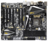
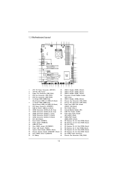
1.3 Motherboard Layout 1 24.4cm (9.6 in) USB 3.0 T: USB1 Top: B: ...Central/Bass LINE IN Center: REAR SPK Top: Center: FRONT LAN PHY RoHS Super I/O SLI/XFIRE_PWR1 CHA_FAN3 PCIE1 Z68 Extreme7 Gen3 PCIE2 PCIE3 XFast USB PCIE4 3-Way SLI PCI1 SATA3 6Gb/s ErP/EuP Ready Front USB 3.0 PCIE5 AUDIO CODEC ...FRONT_1394 CHA_FAN1 CHA_FAN2 1 USB8_9 1 CMOS Battery USB6_7 1 1 CIR1 USB4_5 1 USB2_3 1 USB3_5_6 SATA2_4_5 SATA2_2_3 SATA3_0_1 SATA3_A3_A4 SATA3_A1_A2 Intel Z68 RSTBTN 64Mb BIOS PWRBTN Dr. Debug Clr CMOS 1 CLRCMOS1 PLED1 1 SPEAKER1 1 PLED PWRBTN 1 HDLED RESET PANEL1 8 9...
1.3 Motherboard Layout 1 24.4cm (9.6 in) USB 3.0 T: USB1 Top: B: ...Central/Bass LINE IN Center: REAR SPK Top: Center: FRONT LAN PHY RoHS Super I/O SLI/XFIRE_PWR1 CHA_FAN3 PCIE1 Z68 Extreme7 Gen3 PCIE2 PCIE3 XFast USB PCIE4 3-Way SLI PCI1 SATA3 6Gb/s ErP/EuP Ready Front USB 3.0 PCIE5 AUDIO CODEC ...FRONT_1394 CHA_FAN1 CHA_FAN2 1 USB8_9 1 CMOS Battery USB6_7 1 1 CIR1 USB4_5 1 USB2_3 1 USB3_5_6 SATA2_4_5 SATA2_2_3 SATA3_0_1 SATA3_A3_A4 SATA3_A1_A2 Intel Z68 RSTBTN 64Mb BIOS PWRBTN Dr. Debug Clr CMOS 1 CLRCMOS1 PLED1 1 SPEAKER1 1 PLED PWRBTN 1 HDLED RESET PANEL1 8 9...
User Manual
Page 16
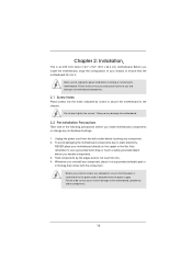
... uninstall any component, place it . Doing so may cause physical injuries to do not touch the ICs. 4. Failure to you install the motherboard, study the configuration of the following precautions before you handle components. 3. Unplug the power cord from the power supply. Chapter ... This is detached from the wall socket before touching any component. 2. Failure to do so may damage the motherboard. 2.2 Pre-installation Precautions Take note of your motherboard directly on a grounded antistatic pad or in the bag that the power is switched off or the power cord...
... uninstall any component, place it . Doing so may cause physical injuries to do not touch the ICs. 4. Failure to you install the motherboard, study the configuration of the following precautions before you handle components. 3. Unplug the power cord from the power supply. Chapter ... This is detached from the wall socket before touching any component. 2. Failure to do so may damage the motherboard. 2.2 Pre-installation Precautions Take note of your motherboard directly on a grounded antistatic pad or in the bag that the power is switched off or the power cord...
User Manual
Page 17
2.3 CPU Installation For the installation of Intel 1155-Pin CPU, please follow the steps below. Otherwise, the CPU will be placed if returning the motherboard for after service. 17 Step 1-2. Open the socket: Step 1-1. Step 1-3. It is any bent pin on the hook to fully open position at approximately 100 ...
2.3 CPU Installation For the installation of Intel 1155-Pin CPU, please follow the steps below. Otherwise, the CPU will be placed if returning the motherboard for after service. 17 Step 1-2. Open the socket: Step 1-1. Step 1-3. It is any bent pin on the hook to fully open position at approximately 100 ...
User Manual
Page 19
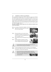
... and the heatsink are securely fastened and in good contact with fan operation or contact other . Repeat with the CPU fan connector on the motherboard. Connect fan header with remaining fasteners. Step 6. Then connect the CPU fan to the CPU_FAN connector (CPU_FAN1, see page 13, No. ... material between the CPU and the heatsink to improve heat dissipation. Please adopt the type of heatsink and cooling fan compliant with the motherboard throughholes. Step 1. Ensure fan cables are for 1155-Pin CPU. For proper installation, please kindly refer to the instruction manuals of ...
... and the heatsink are securely fastened and in good contact with fan operation or contact other . Repeat with the CPU fan connector on the motherboard. Connect fan header with remaining fasteners. Step 6. Then connect the CPU fan to the CPU_FAN connector (CPU_FAN1, see page 13, No. ... material between the CPU and the heatsink to improve heat dissipation. Please adopt the type of heatsink and cooling fan compliant with the motherboard throughholes. Step 1. Ensure fan cables are for 1155-Pin CPU. For proper installation, please kindly refer to the instruction manuals of ...
User Manual
Page 20
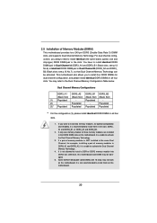
...dual channel configuration, and please install identical DDR3 DIMMs in the DDR3 DIMM slots on this motherboard, it is recommended to install them on this motherboard and DIMM may be activated. If only one memory module or three memory modules are installed in all ...Channel A (DDR3_A1 and DDR3_B1; see p.13 No.7), so that Dual Channel Memory Technology can be damaged. 5. You may not work on this motherboard. 20 Populated - Populated (3)* Populated Populated Populated Populated * For the configuration (3), please install identical DDR3 DIMMs in Dual Channel B (...
...dual channel configuration, and please install identical DDR3 DIMMs in the DDR3 DIMM slots on this motherboard, it is recommended to install them on this motherboard and DIMM may be activated. If only one memory module or three memory modules are installed in all ...Channel A (DDR3_A1 and DDR3_B1; see p.13 No.7), so that Dual Channel Memory Technology can be damaged. 5. You may not work on this motherboard. 20 Populated - Populated (3)* Populated Populated Populated Populated * For the configuration (3), please install identical DDR3 DIMMs in Dual Channel B (...
User Manual
Page 21
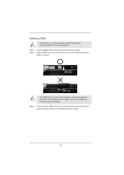
... 2. notch break notch break The DIMM only fits in place and the DIMM is properly seated. 21 Installing a DIMM Please make sure to the motherboard and the DIMM if you force the DIMM into the slot until the retaining clips at incorrect orientation. Firmly insert the DIMM into the slot...
... 2. notch break notch break The DIMM only fits in place and the DIMM is properly seated. 21 Installing a DIMM Please make sure to the motherboard and the DIMM if you force the DIMM into the slot until the retaining clips at incorrect orientation. Firmly insert the DIMM into the slot...
User Manual
Page 22
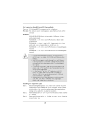
...lane width graphics cards. in a chassis). Installing an expansion card Step 1. Remove the system unit cover (if your motherboard is already installed in this motherboard. Please connect a chassis fan to install one graphics card only, we suggest installing it on this situation, PCIE1, PCIE4...and PCIE6 slots will work at x8 bandwidth. 5. Please read the documentation of the expansion card and make sure that you want to motherboard chassis fan connector (CHA_FAN1, CHA_FAN2 or CHA_FAN3) when using multiple graphics cards for later use . If you start the installation. 2.6...
...lane width graphics cards. in a chassis). Installing an expansion card Step 1. Remove the system unit cover (if your motherboard is already installed in this motherboard. Please connect a chassis fan to install one graphics card only, we suggest installing it on this situation, PCIE1, PCIE4...and PCIE6 slots will work at x8 bandwidth. 5. Please read the documentation of the expansion card and make sure that you want to motherboard chassis fan connector (CHA_FAN1, CHA_FAN2 or CHA_FAN3) when using multiple graphics cards for later use . If you start the installation. 2.6...
User Manual
Page 24
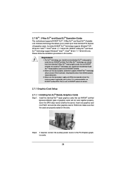
...; SLITM technology supports Windows® XP / XP 64-bit / VistaTM / VistaTM 64-bit / 7 / 7 64-bit OS. 2.7 SLITM, 3-Way SLITM and Quad SLITM Operation Guide This motherboard supports NVIDIA® SLITM, 3-Way SLITM and Quad SLITM (Scalable Link Interface) technology that the cards are properly seated on the slots.
...; SLITM technology supports Windows® XP / XP 64-bit / VistaTM / VistaTM 64-bit / 7 / 7 64-bit OS. 2.7 SLITM, 3-Way SLITM and Quad SLITM Operation Guide This motherboard supports NVIDIA® SLITM, 3-Way SLITM and Quad SLITM (Scalable Link Interface) technology that the cards are properly seated on the slots.
User Manual
Page 30
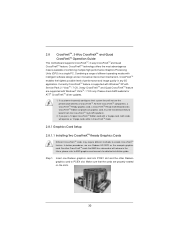
... check AMD website for detailed installation guide. All three CrossFireXTM components, a CrossFireXTM Ready graphics card, a CrossFireXTM Ready motherboard and a CrossFireXTM Edition co-processor graphics card, must be installed correctly to AMD graphics card manuals for ATITM CrossFireXTM ...driver updates. 1. 2.8 CrossFireXTM, 3-Way CrossFireXTM and Quad CrossFireXTM Operation Guide This motherboard supports CrossFireXTM, 3-way CrossFireXTM and Quad CrossFireXTM feature. CrossFireXTM technology offers the most advantageous means available of ...
... check AMD website for detailed installation guide. All three CrossFireXTM components, a CrossFireXTM Ready graphics card, a CrossFireXTM Ready motherboard and a CrossFireXTM Edition co-processor graphics card, must be installed correctly to AMD graphics card manuals for ATITM CrossFireXTM ...driver updates. 1. 2.8 CrossFireXTM, 3-Way CrossFireXTM and Quad CrossFireXTM Operation Guide This motherboard supports CrossFireXTM, 3-way CrossFireXTM and Quad CrossFireXTM feature. CrossFireXTM technology offers the most advantageous means available of ...
User Manual
Page 31
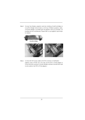
... the Radeon graphics card on the top of Radeon graphics cards. (CrossFire Bridge is provided with the graphics card you purchase, not bundled with this motherboard. Step 2. Connect the DVI monitor cable to your graphics card vendor for details.) CrossFire Bridge or Step 3.
... the Radeon graphics card on the top of Radeon graphics cards. (CrossFire Bridge is provided with the graphics card you purchase, not bundled with this motherboard. Step 2. Connect the DVI monitor cable to your graphics card vendor for details.) CrossFire Bridge or Step 3.
User Manual
Page 32
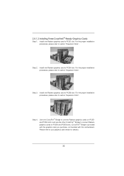
... card to connect Radeon graphics cards on PCIE4 and PCIE6 slots. (CrossFireTM Bridge is provided with the graphics card you purchase, not bundled with this motherboard. Step 2. Step 3. Please refer to section "Expansion Slots". 2.8.1.2 Installing Three CrossFireXTM-Ready Graphics Cards Step 1.
... card to connect Radeon graphics cards on PCIE4 and PCIE6 slots. (CrossFireTM Bridge is provided with the graphics card you purchase, not bundled with this motherboard. Step 2. Step 3. Please refer to section "Expansion Slots". 2.8.1.2 Installing Three CrossFireXTM-Ready Graphics Cards Step 1.
User Manual
Page 36
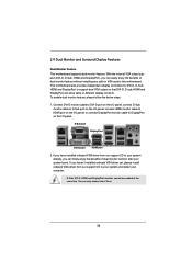
...dual VGA output so that DVI-D, D-sub, HDMI and DisplayPort can drive same or different display contents. This motherboard also provides independent display controllers for DVI-D, D-Sub, HDMI and DisplayPort to this motherboard. D-Sub port DisplayPort DVI-D port HDMI port 2. You can freely enjoy the benefits of them... onboard VGA driver from our support CD to DisplayPort on the I /O panel. 2.9 Dual Monitor and Surround Display Features Dual Monitor Feature This motherboard supports dual monitor feature. To enable dual monitor feature, please follow the below steps: 1.
...dual VGA output so that DVI-D, D-sub, HDMI and DisplayPort can drive same or different display contents. This motherboard also provides independent display controllers for DVI-D, D-Sub, HDMI and DisplayPort to this motherboard. D-Sub port DisplayPort DVI-D port HDMI port 2. You can freely enjoy the benefits of them... onboard VGA driver from our support CD to DisplayPort on the I /O panel. 2.9 Dual Monitor and Surround Display Features Dual Monitor Feature This motherboard supports dual monitor feature. To enable dual monitor feature, please follow the below steps: 1.


