
User Manual
Page 13
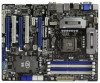
...43 42 41 40 39 38 37 HDMI 1.4a CHA_FAN3 CHA_FAN2 USB 3.0 PCIE1 Z68 Extreme4 PCIE2 DX10.1 LAN PHY PCIE3 PCI Express 2.0 Super I/O PCI1 ErP/EuP Ready PCIE4 CMOS Battery 1 CLRCMOS1 Intel Z68 64Mb BIOS SATA2_4_5 SATA2_2_3 AUDIO CODEC RoHS HD_AUDIO1 1 HDMI_SPDIF1 COM1 1 1 PCI2...27 26 25 24 1 ATX 12V Power Connector (ATX12V1) 26 USB 3.0 Header (USB3_12_13, Light Blue) 2 Power Fan Connector (PWR_FAN1) 27 Dr. Debug 3 1155-Pin CPU Socket 28 USB 2.0 Header (USB10_11, Blue) 4 CPU Fan Connector (CPU_FAN1) 29 USB 2.0 Header (USB8_9, Blue) 5 CPU Fan Connector (CPU_FAN2) 30 USB 2.0...
...43 42 41 40 39 38 37 HDMI 1.4a CHA_FAN3 CHA_FAN2 USB 3.0 PCIE1 Z68 Extreme4 PCIE2 DX10.1 LAN PHY PCIE3 PCI Express 2.0 Super I/O PCI1 ErP/EuP Ready PCIE4 CMOS Battery 1 CLRCMOS1 Intel Z68 64Mb BIOS SATA2_4_5 SATA2_2_3 AUDIO CODEC RoHS HD_AUDIO1 1 HDMI_SPDIF1 COM1 1 1 PCI2...27 26 25 24 1 ATX 12V Power Connector (ATX12V1) 26 USB 3.0 Header (USB3_12_13, Light Blue) 2 Power Fan Connector (PWR_FAN1) 27 Dr. Debug 3 1155-Pin CPU Socket 28 USB 2.0 Header (USB10_11, Blue) 4 CPU Fan Connector (CPU_FAN1) 29 USB 2.0 Header (USB8_9, Blue) 5 CPU Fan Connector (CPU_FAN2) 30 USB 2.0...

Quick Installation Guide
Page 2
... 29 28 27 26 25 24 1 ATX 12V Power Connector (ATX12V1) 26 USB 3.0 Header (USB3_12_13, Light Blue) 2 Power Fan Connector (PWR_FAN1) 27 Dr. Debug 3 1155-Pin CPU Socket 28 USB 2.0 Header (USB10_11, Blue) 4 CPU Fan Connector (CPU_FAN1) 29 USB 2.0 Header (USB8_9, Blue) 5 CPU Fan Connector (CPU_FAN2) 30 USB 2.0 Header (USB6_7, Blue) 6 2 x 240... LED Header (PLED1) 46 Chassis Fan Connector (CHA_FAN3) 24 System Panel Header (PANEL1, White) 47 Chassis Fan Connector (CHA_FAN2) 25 Chassis Speaker Header (SPEAKER 1, White) 2 ASRock Z68 Extreme4 Motherboard English
... 29 28 27 26 25 24 1 ATX 12V Power Connector (ATX12V1) 26 USB 3.0 Header (USB3_12_13, Light Blue) 2 Power Fan Connector (PWR_FAN1) 27 Dr. Debug 3 1155-Pin CPU Socket 28 USB 2.0 Header (USB10_11, Blue) 4 CPU Fan Connector (CPU_FAN1) 29 USB 2.0 Header (USB8_9, Blue) 5 CPU Fan Connector (CPU_FAN2) 30 USB 2.0 Header (USB6_7, Blue) 6 2 x 240... LED Header (PLED1) 46 Chassis Fan Connector (CHA_FAN3) 24 System Panel Header (PANEL1, White) 47 Chassis Fan Connector (CHA_FAN2) 25 Chassis Speaker Header (SPEAKER 1, White) 2 ASRock Z68 Extreme4 Motherboard English
Quick Installation Guide
Page 12
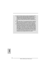
... power efficiency is detected, the system will automatically shutdown. According to define the power consumption for more details. 12 ASRock Z68 Extreme4 Motherboard English EuP, stands for Energy Using Product, was a provision regulated by European Union to Intel's suggestion, the EuP ready power supply... unplug the power cord, then plug it back again. To improve heat dissipation, remember to adopt three different CPU cooler types, Socket LGA 775, LGA 1155 and LGA 1156. Before you install the PC system. 18. While CPU overheat is higher than 50% under 1.00W in off...
... power efficiency is detected, the system will automatically shutdown. According to define the power consumption for more details. 12 ASRock Z68 Extreme4 Motherboard English EuP, stands for Energy Using Product, was a provision regulated by European Union to Intel's suggestion, the EuP ready power supply... unplug the power cord, then plug it back again. To improve heat dissipation, remember to adopt three different CPU cooler types, Socket LGA 775, LGA 1155 and LGA 1156. Before you install the PC system. 18. While CPU overheat is higher than 50% under 1.00W in off...
Quick Installation Guide
Page 13
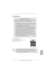
... holes to the motherboard, peripherals, and/or components. 2. Failure to do not touch the ICs. 4. English 13 ASRock Z68 Extreme4 Motherboard Unplug the power cord from the wall socket before you insert the 1155-Pin CPU into the socket if above situation is any motherboard settings. 1. Doing so may cause severe damage to secure the moth...
... holes to the motherboard, peripherals, and/or components. 2. Failure to do not touch the ICs. 4. English 13 ASRock Z68 Extreme4 Motherboard Unplug the power cord from the wall socket before you insert the 1155-Pin CPU into the socket if above situation is any motherboard settings. 1. Doing so may cause severe damage to secure the moth...
Quick Installation Guide
Page 14
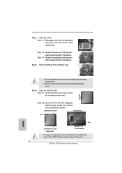
... to match the two orientation key notches of the CPU with the two alignment keys of the socket. 14 ASRock Z68 Extreme4 Motherboard orientation key notch alignment key Pin1 Pin1 orientation key notch 1155-Pin CPU alignment key 1155-Pin Socket For proper inserting, please ensure to handle and avoid kicking off the PnP cap. 2. Step 1-2. Insert...
... to match the two orientation key notches of the CPU with the two alignment keys of the socket. 14 ASRock Z68 Extreme4 Motherboard orientation key notch alignment key Pin1 Pin1 orientation key notch 1155-Pin CPU alignment key 1155-Pin Socket For proper inserting, please ensure to handle and avoid kicking off the PnP cap. 2. Step 1-2. Insert...
Quick Installation Guide
Page 15
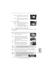
... material onto center of IHS on the motherboard. Fan cables on side closest to the instruction manuals of the heatsink for Socket LGA 1155/1156 CPU fan. 15 ASRock Z68 Extreme4 Motherboard Step 3. Align fasteners with load plate tab under retention tab of load lever. 2.2 Installation of CPU Fan and... rotating them clockwise, the heatsink cannot be noticed that the CPU is an example to adopt three different CPU cooler types, Socket LGA 775, LGA 1155 and LGA 1156. Repeat with fan operation or contact other components. Step 6. Secure excess cable with tie-wrap to the ...
... material onto center of IHS on the motherboard. Fan cables on side closest to the instruction manuals of the heatsink for Socket LGA 1155/1156 CPU fan. 15 ASRock Z68 Extreme4 Motherboard Step 3. Align fasteners with load plate tab under retention tab of load lever. 2.2 Installation of CPU Fan and... rotating them clockwise, the heatsink cannot be noticed that the CPU is an example to adopt three different CPU cooler types, Socket LGA 775, LGA 1155 and LGA 1156. Repeat with fan operation or contact other components. Step 6. Secure excess cable with tie-wrap to the ...

Quick Installation Guide
Page 225
2 1 2 3 IC 4 5 2.1 CPU 설치 Intel 1155 핀 CPU 장착판 Load Plate Load Lever Contact Array Socket Body 1155 1155 핀 CPU CPU CPU CPU 한국어 225 ASRock Z68 Extreme4 Motherboard
2 1 2 3 IC 4 5 2.1 CPU 설치 Intel 1155 핀 CPU 장착판 Load Plate Load Lever Contact Array Socket Body 1155 1155 핀 CPU CPU CPU CPU 한국어 225 ASRock Z68 Extreme4 Motherboard

Quick Installation Guide
Page 252
IC 4. 2.1 CPU Intel 1155-LAND CPU Load Plate Load Lever Contact Array Socket Body 1155 1155-LAND CPU CPU CPU CPU 1 1-1 日本語 252 ASRock Z68 Extreme4 Motherboard 1. 2. 3.
IC 4. 2.1 CPU Intel 1155-LAND CPU Load Plate Load Lever Contact Array Socket Body 1155 1155-LAND CPU CPU CPU CPU 1 1-1 日本語 252 ASRock Z68 Extreme4 Motherboard 1. 2. 3.

Quick Installation Guide
Page 254
4 4-1 HIS 4-2 4-3 2.2 CPU CPU 以下は、1155-LAND CPU 1 HIS Apply Thermal Interface Material 2 CPU_FAN1、2 No. 4 CPU 3 4 Fan cables on side closest to MB header Fastener slots pointing straight out Press Down (4 Places) 5 CPU 6 C.C.O Socket LGA 775、LGA 1155 と LGA 1156 の 3 CPU Socket LGA 1155/1156 CPU 日本語 254 ASRock Z68 Extreme4 Motherboard
4 4-1 HIS 4-2 4-3 2.2 CPU CPU 以下は、1155-LAND CPU 1 HIS Apply Thermal Interface Material 2 CPU_FAN1、2 No. 4 CPU 3 4 Fan cables on side closest to MB header Fastener slots pointing straight out Press Down (4 Places) 5 CPU 6 C.C.O Socket LGA 775、LGA 1155 と LGA 1156 の 3 CPU Socket LGA 1155/1156 CPU 日本語 254 ASRock Z68 Extreme4 Motherboard

Quick Installation Guide
Page 277
2 安全防范 1 2 3 4 5 2.1 CPU 安裝 要安裝 Intel 1155 針 CPU Load Plate Load Lever Contact Array Socket Body 1155 在您將 1155 針 CPU CPU CPU CPU 步驟 1. 1-1 簡體中文 277 ASRock Z68 Extreme4 Motherboard
2 安全防范 1 2 3 4 5 2.1 CPU 安裝 要安裝 Intel 1155 針 CPU Load Plate Load Lever Contact Array Socket Body 1155 在您將 1155 針 CPU CPU CPU CPU 步驟 1. 1-1 簡體中文 277 ASRock Z68 Extreme4 Motherboard

Quick Installation Guide
Page 303
2 安全防範 1 2 3 4 5 2.1 CPU 安裝 要安裝 Intel 1155 針 CPU Load Plate Load Lever Contact Array Socket Body ( 插槽 ) 1155 在您將 1155 針 CPU CPU CPU CPU 步驟 1. 1-1 繁體中文 303 ASRock Z68 Extreme4 Motherboard
2 安全防範 1 2 3 4 5 2.1 CPU 安裝 要安裝 Intel 1155 針 CPU Load Plate Load Lever Contact Array Socket Body ( 插槽 ) 1155 在您將 1155 針 CPU CPU CPU CPU 步驟 1. 1-1 繁體中文 303 ASRock Z68 Extreme4 Motherboard
