
Intel Rapid Storage Guide
Page 1
... drives in the event of data on data-intensive applications. AHCI also delivers longer battery life with RAID 1 can reduce the power consumption of faster boot times and data reads. By seamlessly storing copies of a hard drive failure. By combining from two to drive load balancing, even systems with Link Power...
... drives in the event of data on data-intensive applications. AHCI also delivers longer battery life with RAID 1 can reduce the power consumption of faster boot times and data reads. By seamlessly storing copies of a hard drive failure. By combining from two to drive load balancing, even systems with Link Power...
Intel Rapid Storage Guide
Page 15
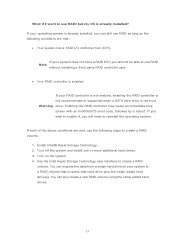
... create a RAID volume. If your RAID controller is not enabled, enabling the RAID controller is not recommended or supported when a SATA hard drive is the boot Warning drive. If your operating system is already installed, you will need to reinstall the operating system. Install Intel® Rapid Storage Technology. 2. What if...
... create a RAID volume. If your RAID controller is not enabled, enabling the RAID controller is not recommended or supported when a SATA hard drive is the boot Warning drive. If your operating system is already installed, you will need to reinstall the operating system. Install Intel® Rapid Storage Technology. 2. What if...

Intel Smart Response Installation Guide
Page 1
... to desktop, open , click on the "Enable Acceleration" button on the GUI panel. 5. For all required drivers, including RST storage driver version 10.5 or later. 2. Boot system to use RST function, you intend to a RAID mode system, then install all performance testing, chose "Maximized" mode. 7. You MUST have both the HDD... Icon tray, lower right-hand corner of the screen. 4. For the new version RST driver, please check our website for the latest information: http://www.asrock.com * Before you use Enhanced or Maximized Mode. 6.
... to desktop, open , click on the "Enable Acceleration" button on the GUI panel. 5. For all required drivers, including RST storage driver version 10.5 or later. 2. Boot system to use RST function, you intend to a RAID mode system, then install all performance testing, chose "Maximized" mode. 7. You MUST have both the HDD... Icon tray, lower right-hand corner of the screen. 4. For the new version RST driver, please check our website for the latest information: http://www.asrock.com * Before you use Enhanced or Maximized Mode. 6.

User Manual
Page 4
...figuration 66 3.4.5 Super IO Configuration 67 3.4.6 ACPI Configuration 68 3.4.7 USB Configuration 69 3.5 Hardware Health Event Monitoring Screen 70 3.6 Boot Screen 71 3.7 Security Screen 72 3.8 Exit Screen 73 4 Software Support 74 4.1 Install Operating System 74 4.2 Support CD Information 74 4.2.1 Running Support CD 74 4.2.2 Drivers Menu...
...figuration 66 3.4.5 Super IO Configuration 67 3.4.6 ACPI Configuration 68 3.4.7 USB Configuration 69 3.5 Hardware Health Event Monitoring Screen 70 3.6 Boot Screen 71 3.7 Security Screen 72 3.8 Exit Screen 73 4 Software Support 74 4.1 Install Operating System 74 4.2 Support CD Information 74 4.2.1 Running Support CD 74 4.2.2 Drivers Menu...

User Manual
Page 8
...PLL, VTT, VCCSA Voltage Multi-adjustment - OEM) - ASRock SmartView (see CAUTION 15) - Boot Failure Guard (B.F.G.) - CPU/Chassis/Power FAN connector - 24 pin ATX power connector - 8 pin 12V power connector - Lucid Virtu (see CAUTION 12) - ASRock U-COP (see CAUTION 19) - Combo Cooler Option ... - 64Mb AMI BIOS - Drivers, Utilities, AntiVirus Software (Trial Version), CyberLink MediaEspresso 6.5 Trial, ASRock Software Suite (CyberLink DVD Suite - ASRock Extreme Tuning Utility (AXTU) (see CAUTION 9) - Hybrid Booster: - ASRock Instant Boot - OEM and Trial;
...PLL, VTT, VCCSA Voltage Multi-adjustment - OEM) - ASRock SmartView (see CAUTION 15) - Boot Failure Guard (B.F.G.) - CPU/Chassis/Power FAN connector - 24 pin ATX power connector - 8 pin 12V power connector - Lucid Virtu (see CAUTION 12) - ASRock U-COP (see CAUTION 19) - Combo Cooler Option ... - 64Mb AMI BIOS - Drivers, Utilities, AntiVirus Software (Trial Version), CyberLink MediaEspresso 6.5 Trial, ASRock Software Suite (CyberLink DVD Suite - ASRock Extreme Tuning Utility (AXTU) (see CAUTION 9) - Hybrid Booster: - ASRock Instant Boot - OEM and Trial;

User Manual
Page 29
... system, there is an optional download. Step 2. You must have Windows® XP Service Pack 2 or higher installed in your system. Restart your computer and boot into OS. Please check AMD website for details. Step 4. Please check Microsoft website for details. Install the VGA card drivers to downloading and installing the...
... system, there is an optional download. Step 2. You must have Windows® XP Service Pack 2 or higher installed in your system. Restart your computer and boot into OS. Please check AMD website for details. Step 4. Please check Microsoft website for details. Install the VGA card drivers to downloading and installing the...

User Manual
Page 31
... feature without installing any add-on the I /O panel, connect HDMI monitor cable to HDMI port on VGA card to your system and restart your system boots. To enable dual monitor feature, please follow the below steps: 1. 2.9 Dual Monitor and Surround Display Features Dual Monitor Feature This motherboard supports dual monitor feature...
... feature without installing any add-on the I /O panel, connect HDMI monitor cable to HDMI port on VGA card to your system and restart your system boots. To enable dual monitor feature, please follow the below steps: 1. 2.9 Dual Monitor and Surround Display Features Dual Monitor Feature This motherboard supports dual monitor feature...

User Manual
Page 32
... my Windows desktop onto this motherboard. 4. Click "Apply" or "OK" to enter UEFI setup. Repeat steps C through E for details. 2. Please refer to the steps below. Boot your system. Please make sure that you do not adjust the UEFI setup, the default value of "Onboard VGA Share Memory", [Auto], will be designated...
... my Windows desktop onto this motherboard. 4. Click "Apply" or "OK" to enter UEFI setup. Repeat steps C through E for details. 2. Please refer to the steps below. Boot your system. Please make sure that you do not adjust the UEFI setup, the default value of "Onboard VGA Share Memory", [Auto], will be designated...

User Manual
Page 34
.... Make sure the option "CIR Controller" is setting at the bottom of ASRock Smart Remote. Step4. Boot up your system and install Multi-Angle CIR Receiver to the USB 2.0 header (as below procedures for ASRock motherboard with CIR header. Find the CIR header located next to below ,... and the USB_PWR PP+ GND DUMMY pin assignments are matched correctly. 2.10 ASRock Smart Remote Installation Guide ASRock Smart Remote is only used for the quick installation and usage of driver list.) 34 Execute ASRock support CD and install CIR Driver. (It is listed at [Enabled]. (...
.... Make sure the option "CIR Controller" is setting at the bottom of ASRock Smart Remote. Step4. Boot up your system and install Multi-Angle CIR Receiver to the USB 2.0 header (as below procedures for ASRock motherboard with CIR header. Find the CIR header located next to below ,... and the USB_PWR PP+ GND DUMMY pin assignments are matched correctly. 2.10 ASRock Smart Remote Installation Guide ASRock Smart Remote is only used for the quick installation and usage of driver list.) 34 Execute ASRock support CD and install CIR Driver. (It is listed at [Enabled]. (...

User Manual
Page 35
Please install it on the market. 3. Only one of ASRock motherboards. Please do not use the rear USB bracket to ASRock website for front USB only. Multi-Angle CIR Receiver can receive the multi-direction infrared signals (top, down and front), which is only supported by ... does not support Hot-Plug function. When the CIR function is used for the motherboard support list: http://www.asrock.com 35 Please refer to connect it before you boot the system. * ASRock Smart Remote is compatible with most of the chassis on the rear panel. Multi-Angle CIR Receiver is enabled, the...
Please install it on the market. 3. Only one of ASRock motherboards. Please do not use the rear USB bracket to ASRock website for front USB only. Multi-Angle CIR Receiver can receive the multi-direction infrared signals (top, down and front), which is only supported by ... does not support Hot-Plug function. When the CIR function is used for the motherboard support list: http://www.asrock.com 35 Please refer to connect it before you boot the system. * ASRock Smart Remote is compatible with most of the chassis on the rear panel. Multi-Angle CIR Receiver is enabled, the...

User Manual
Page 36
... Description Note: CLRCMOS1 allows you update the BIOS. If you need to clear the CMOS when you just finish updating the BIOS, you must boot up the system first, and then shut it down before you do not clear the CMOS right after you to clear the data in...
... Description Note: CLRCMOS1 allows you update the BIOS. If you need to clear the CMOS when you just finish updating the BIOS, you must boot up the system first, and then shut it down before you do not clear the CMOS right after you to clear the data in...

User Manual
Page 43
... after microcode loading OEM initialization after microcode loading Cache initialization Reserved for reading the Dr. Debug codes. Serial Presence Detect (SPD) data reading Memory initialization. Boot Strap Processor (BSP) selection CPU post-memory initialization. Programming memory timing information Memory initialization. Status Code 0x00 0x01 0x02 0x03 0x04 0x05 0x06 0x07 0x08...
... after microcode loading OEM initialization after microcode loading Cache initialization Reserved for reading the Dr. Debug codes. Serial Presence Detect (SPD) data reading Memory initialization. Boot Strap Processor (BSP) selection CPU post-memory initialization. Programming memory timing information Memory initialization. Status Code 0x00 0x01 0x02 0x03 0x04 0x05 0x06 0x07 0x08...

User Manual
Page 44
... reset PPI is not available Reserved for future AMI error codes S3 Resume is stared (S3 Resume PPI is called by the DXE IPL) S3 Boot Script execution Video repost OS S3 wake vector call Reserved for future AMI progress codes S3 Resume Failed S3 Resume PPI not Found S3 Resume... Boot Script Error S3 OS Wake Error Reserved for future AMI error codes Recovery condition triggered by firmware (Auto recovery) Recovery condition triggered by user (...
... reset PPI is not available Reserved for future AMI error codes S3 Resume is stared (S3 Resume PPI is called by the DXE IPL) S3 Boot Script execution Video repost OS S3 wake vector call Reserved for future AMI progress codes S3 Resume Failed S3 Resume PPI not Found S3 Resume... Boot Script Error S3 OS Wake Error Reserved for future AMI error codes Recovery condition triggered by firmware (Auto recovery) Recovery condition triggered by user (...

User Manual
Page 45
...fic) South Bridge DXE Initialization (South Bridge module specific) ACPI module initialization CSM initialization Reserved for future AMI DXE codes OEM DXE initialization codes Boot Device Selection (BDS) phase is started Driver connecting is started PCI Bus initialization is started PCI Bus Hot Plug Controller Initialization PCI Bus Enumeration PCI...
...fic) South Bridge DXE Initialization (South Bridge module specific) ACPI module initialization CSM initialization Reserved for future AMI DXE codes OEM DXE initialization codes Boot Device Selection (BDS) phase is started Driver connecting is started PCI Bus initialization is started PCI Bus Hot Plug Controller Initialization PCI Bus Enumeration PCI...

User Manual
Page 46
... ASL (see ASL Status Codes section below) Setup Input Wait Reserved for ASL (see ASL Status Codes section below) Ready To Boot event Legacy Boot event Exit Boot Services event Runtime Set Virtual Address MAP Begin Runtime Set Virtual Address MAP End Legacy Option ROM Initialization System Reset USB hot plug... PCI bus hot plug Clean-up of NVRAM Configuration Reset (reset of the Architectural Protocols are found Invalid password Error loading Boot Option (LoadImage returned error) Boot Option is failed (StartImage returned error) Flash update is failed Reset protocol is not available 46
... ASL (see ASL Status Codes section below) Setup Input Wait Reserved for ASL (see ASL Status Codes section below) Ready To Boot event Legacy Boot event Exit Boot Services event Runtime Set Virtual Address MAP Begin Runtime Set Virtual Address MAP End Legacy Option ROM Initialization System Reset USB hot plug... PCI bus hot plug Clean-up of NVRAM Configuration Reset (reset of the Architectural Protocols are found Invalid password Error loading Boot Option (LoadImage returned error) Boot Option is failed (StartImage returned error) Flash update is failed Reset protocol is not available 46

User Manual
Page 53
... system time/date information OC Tweaker To set up overclocking features Advanced To set up the advanced UEFI features H/W Monitor To display current hardware status Boot To set up the default system device to configure your screen. 3.1.1 UEFI Menu Bar The top of the screen has a menu bar with...
... system time/date information OC Tweaker To set up overclocking features Advanced To set up the advanced UEFI features H/W Monitor To display current hardware status Boot To set up the default system device to configure your screen. 3.1.1 UEFI Menu Bar The top of the screen has a menu bar with...

User Manual
Page 57
... [Auto]. RAS to RAS Delay (tRRD) Use this item to change Row Precharge Time (tRP) Auto/Manual setting. The default is [Auto]. 57 Memory Fast Boot Use this item to adjust DDR power down mode. The default is [Auto]. Read to Precharge (tRTP) Use this item to change RAS# Active Time... item to change Refresh Cyle Time (tRFC) Auto/Manual setting. The default is [Auto]. Memory Power Down Mode Use this item to adjust DDR fast boot mode. ODT WR (CHA) Use this item to change Command Rate (CR) Auto/Manual setting. The default is [Auto]. The default is [Auto]. The default...
... [Auto]. RAS to RAS Delay (tRRD) Use this item to change Row Precharge Time (tRP) Auto/Manual setting. The default is [Auto]. 57 Memory Fast Boot Use this item to adjust DDR power down mode. The default is [Auto]. Read to Precharge (tRTP) Use this item to change RAS# Active Time... item to change Refresh Cyle Time (tRFC) Auto/Manual setting. The default is [Auto]. Memory Power Down Mode Use this item to adjust DDR fast boot mode. ODT WR (CHA) Use this item to change Command Rate (CR) Auto/Manual setting. The default is [Auto]. The default is [Auto]. The default...

User Manual
Page 62
... is [1024M]. For Windows® XP / XP 64-bit / VistaTM / VistaTM 64-bit users, if you to select [Onboard], [PCI] or [PCI Express] as the boot graphic adapter priority. VT-d Use this to disable the onboard VGA in advance. 62 The default value is [Disabled]. Render Standby Use this feature is...
... is [1024M]. For Windows® XP / XP 64-bit / VistaTM / VistaTM 64-bit users, if you to select [Onboard], [PCI] or [PCI Express] as the boot graphic adapter priority. VT-d Use this to disable the onboard VGA in advance. 62 The default value is [Disabled]. Render Standby Use this feature is...

User Manual
Page 64
... The default value is [Enabled]. If you to enable or disable the "Onboard HDMI HD Audio" feature. If you plan to use this item to boot up when the power recovers. On/Off Play Use this option to [Enabled] if you want to enable Deep Sx, please disable On/Off Play...
... The default value is [Enabled]. If you to enable or disable the "Onboard HDMI HD Audio" feature. If you plan to use this item to boot up when the power recovers. On/Off Play Use this option to [Enabled] if you want to enable Deep Sx, please disable On/Off Play...

User Manual
Page 71
...64257;guration options: [Legacy ROM] and [EFI Compatible ROM]. The default value is [Legacy ROM]. Configuration options: [Enabled] and [Disabled]. Boot Failure Guard Enable or disable the feature of multiple Option ROMs (Legacy and EFI Compatible), specifies what PCI Option ROM to launch. Setup ...Prompt Timeout This shows the number of Boot Failure Guard Count. 71 The default vale is [Enabled]. If you enable the option "Full Screen Logo" but you to see the AddOn ...
...64257;guration options: [Legacy ROM] and [EFI Compatible ROM]. The default value is [Legacy ROM]. Configuration options: [Enabled] and [Disabled]. Boot Failure Guard Enable or disable the feature of multiple Option ROMs (Legacy and EFI Compatible), specifies what PCI Option ROM to launch. Setup ...Prompt Timeout This shows the number of Boot Failure Guard Count. 71 The default vale is [Enabled]. If you enable the option "Full Screen Logo" but you to see the AddOn ...

