
Intel Rapid Storage Guide
Page 1
... provides new levels of protection, performance, and expandability for any one or more than one or multiple hard drives, users can take advantage of faster boot times and data reads. Intel Rapid Storage Technology can also improve the performance of a single drive as editing home video. Intel Rapid Storage Technology provides...
... provides new levels of protection, performance, and expandability for any one or more than one or multiple hard drives, users can take advantage of faster boot times and data reads. Intel Rapid Storage Technology can also improve the performance of a single drive as editing home video. Intel Rapid Storage Technology provides...
Intel Rapid Storage Guide
Page 15
... be able to use the following conditions are met, use RAID Note without installing a third-party RAID controller card. • Your RAID controller is the boot Warning drive. If your RAID controller is not enabled, enabling the RAID controller is not recommended or supported when a SATA hard drive is enabled. Turn...
... be able to use the following conditions are met, use RAID Note without installing a third-party RAID controller card. • Your RAID controller is the boot Warning drive. If your RAID controller is not enabled, enabling the RAID controller is not recommended or supported when a SATA hard drive is enabled. Turn...

Intel Smart Response Installation Guide
Page 1
... lower right-hand corner of the screen. 4. For the new version RST driver, please check our website for the latest information: http://www.asrock.com * Before you use RST function, you intend to [RAID Mode]. You can find the UI setup instruction and the step by double-...clicking RST Storage icon in system at this point! 3. Boot system to a RAID mode system, then install all performance testing, chose "Maximized" mode. 7. For all required drivers, including RST storage driver version...
... lower right-hand corner of the screen. 4. For the new version RST driver, please check our website for the latest information: http://www.asrock.com * Before you use RST function, you intend to [RAID Mode]. You can find the UI setup instruction and the step by double-...clicking RST Storage icon in system at this point! 3. Boot system to a RAID mode system, then install all performance testing, chose "Maximized" mode. 7. For all required drivers, including RST storage driver version...

User Manual
Page 4
...figuration 66 3.4.5 Super IO Configuration 67 3.4.6 ACPI Configuration 68 3.4.7 USB Configuration 69 3.5 Hardware Health Event Monitoring Screen 70 3.6 Boot Screen 71 3.7 Security Screen 72 3.8 Exit Screen 73 4 Software Support 74 4.1 Install Operating System 74 4.2 Support CD Information 74 4.2.1 Running Support CD 74 4.2.2 Drivers Menu...
...figuration 66 3.4.5 Super IO Configuration 67 3.4.6 ACPI Configuration 68 3.4.7 USB Configuration 69 3.5 Hardware Health Event Monitoring Screen 70 3.6 Boot Screen 71 3.7 Security Screen 72 3.8 Exit Screen 73 4 Software Support 74 4.1 Install Operating System 74 4.2 Support CD Information 74 4.2.1 Running Support CD 74 4.2.2 Drivers Menu...

User Manual
Page 8
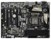
... (see CAUTION 11) - Hybrid Booster: - Good Night LED 8 Supports "Plug and Play" - OEM and Trial; ASRock MAGIX Multimedia Suite - ASRock APP Charger (see CAUTION 14) - ASRock XFast USB (see CAUTION 17) - Boot Failure Guard (B.F.G.) - ACPI 1.1 Compliance Wake Up Events - ASRock Instant Boot - Front panel audio connector - 4 x USB 2.0 headers (support 8 USB 2.0 ports) - 1 x Dr. Debug (7-Segment Debug LED...
... (see CAUTION 11) - Hybrid Booster: - Good Night LED 8 Supports "Plug and Play" - OEM and Trial; ASRock MAGIX Multimedia Suite - ASRock APP Charger (see CAUTION 14) - ASRock XFast USB (see CAUTION 17) - Boot Failure Guard (B.F.G.) - ACPI 1.1 Compliance Wake Up Events - ASRock Instant Boot - Front panel audio connector - 4 x USB 2.0 headers (support 8 USB 2.0 ports) - 1 x Dr. Debug (7-Segment Debug LED...

User Manual
Page 29
... 2 or higher installed in your Windows® taskbar. AMD recommends Windows® XP Service Pack 2 or higher to your system, and restart your computer and boot into OS. Install the VGA card drivers to be installed (If you will find "ATI Catalyst Control Center" on your computer. Power on your...
... 2 or higher installed in your Windows® taskbar. AMD recommends Windows® XP Service Pack 2 or higher to your system, and restart your computer and boot into OS. Install the VGA card drivers to be installed (If you will find "ATI Catalyst Control Center" on your computer. Power on your...

User Manual
Page 31
... feature without installing any add-on the I /O panel, connect HDMI monitor cable to HDMI port on VGA card to your system and restart your system boots. If you can drive same or different display contents. If you can only choose two of dual monitor function after your computer. With the internal...
... feature without installing any add-on the I /O panel, connect HDMI monitor cable to HDMI port on VGA card to your system and restart your system boots. If you can drive same or different display contents. If you can only choose two of dual monitor function after your computer. With the internal...

User Manual
Page 32
... Secondary. Repeat steps C through E for details. 2. Please make sure that you have installed the drivers already, there is no need to apply these new values. A. G. Boot your card, one to the steps below. Click "Extend my Windows desktop onto this motherboard. 4. F. Click "Apply" or "OK" to install them again. 5. Please refer...
... Secondary. Repeat steps C through E for details. 2. Please make sure that you have installed the drivers already, there is no need to apply these new values. A. G. Boot your card, one to the steps below. Click "Extend my Windows desktop onto this motherboard. 4. F. Click "Apply" or "OK" to install them again. 5. Please refer...

User Manual
Page 34
...gray) Step2. Connect the front USB cable to the other front USB port then try again. Boot up your system and install Multi-Angle CIR Receiver to the USB 2.0 header (as below procedures for ASRock motherboard with CIR header. Step5. Enter Windows. GND IRTX IRRX ATX+5VSB Step3. Make sure... the option "CIR Controller" is setting at the bottom of ASRock Smart Remote. Step1. Press or to the USB 2.0 header on ASRock motherboard. Execute ASRock support CD and install CIR Driver. (It is only used for the quick installation and usage of driver...
...gray) Step2. Connect the front USB cable to the other front USB port then try again. Boot up your system and install Multi-Angle CIR Receiver to the USB 2.0 header (as below procedures for ASRock motherboard with CIR header. Step5. Enter Windows. GND IRTX IRRX ATX+5VSB Step3. Make sure... the option "CIR Controller" is setting at the bottom of ASRock Smart Remote. Step1. Press or to the USB 2.0 header on ASRock motherboard. Execute ASRock support CD and install CIR Driver. (It is only used for the quick installation and usage of driver...

User Manual
Page 35
... port will remain USB function. 2. Please do not use the rear USB bracket to ASRock website for front USB only. Please refer to connect it before you boot the system. * ASRock Smart Remote is compatible with most of ASRock motherboards. The Multi-Angle CIR Receiver does not support Hot-Plug function. Multi-Angle CIR...
... port will remain USB function. 2. Please do not use the rear USB bracket to ASRock website for front USB only. Please refer to connect it before you boot the system. * ASRock Smart Remote is compatible with most of ASRock motherboards. The Multi-Angle CIR Receiver does not support Hot-Plug function. Multi-Angle CIR...

User Manual
Page 36
... the data in CMOS. To clear and reset the system parameters to clear the CMOS when you just finish updating the BIOS, you must boot up the system first, and then shut it down before you do not clear the CMOS right after you need to default setup, please...
... the data in CMOS. To clear and reset the system parameters to clear the CMOS when you just finish updating the BIOS, you must boot up the system first, and then shut it down before you do not clear the CMOS right after you need to default setup, please...

User Manual
Page 43
... initialization (North Bridge module specific) Pre-memory South Bridge initialization is started CPU post-memory initialization. Serial Presence Detect (SPD) data reading Memory initialization. Boot Strap Processor (BSP) selection CPU post-memory initialization. Please see ASL Status Codes section below for ASL (see the diagrams below ) Memory Installed CPU post...
... initialization (North Bridge module specific) Pre-memory South Bridge initialization is started CPU post-memory initialization. Serial Presence Detect (SPD) data reading Memory initialization. Boot Strap Processor (BSP) selection CPU post-memory initialization. Please see ASL Status Codes section below for ASL (see the diagrams below ) Memory Installed CPU post...

User Manual
Page 44
... reset PPI is not available Reserved for future AMI error codes S3 Resume is stared (S3 Resume PPI is called by the DXE IPL) S3 Boot Script execution Video repost OS S3 wake vector call Reserved for future AMI progress codes S3 Resume Failed S3 Resume PPI not Found S3 Resume... Boot Script Error S3 OS Wake Error Reserved for future AMI error codes Recovery condition triggered by firmware (Auto recovery) Recovery condition triggered by user (...
... reset PPI is not available Reserved for future AMI error codes S3 Resume is stared (S3 Resume PPI is called by the DXE IPL) S3 Boot Script execution Video repost OS S3 wake vector call Reserved for future AMI progress codes S3 Resume Failed S3 Resume PPI not Found S3 Resume... Boot Script Error S3 OS Wake Error Reserved for future AMI error codes Recovery condition triggered by firmware (Auto recovery) Recovery condition triggered by user (...

User Manual
Page 45
...fic) South Bridge DXE Initialization (South Bridge module specific) ACPI module initialization CSM initialization Reserved for future AMI DXE codes OEM DXE initialization codes Boot Device Selection (BDS) phase is started Driver connecting is started PCI Bus initialization is started PCI Bus Hot Plug Controller Initialization PCI Bus Enumeration PCI...
...fic) South Bridge DXE Initialization (South Bridge module specific) ACPI module initialization CSM initialization Reserved for future AMI DXE codes OEM DXE initialization codes Boot Device Selection (BDS) phase is started Driver connecting is started PCI Bus initialization is started PCI Bus Hot Plug Controller Initialization PCI Bus Enumeration PCI...

User Manual
Page 46
... ASL (see ASL Status Codes section below) Setup Input Wait Reserved for ASL (see ASL Status Codes section below) Ready To Boot event Legacy Boot event Exit Boot Services event Runtime Set Virtual Address MAP Begin Runtime Set Virtual Address MAP End Legacy Option ROM Initialization System Reset USB hot plug... PCI bus hot plug Clean-up of NVRAM Configuration Reset (reset of the Architectural Protocols are found Invalid password Error loading Boot Option (LoadImage returned error) Boot Option is failed (StartImage returned error) Flash update is failed Reset protocol is not available 46
... ASL (see ASL Status Codes section below) Setup Input Wait Reserved for ASL (see ASL Status Codes section below) Ready To Boot event Legacy Boot event Exit Boot Services event Runtime Set Virtual Address MAP Begin Runtime Set Virtual Address MAP End Legacy Option ROM Initialization System Reset USB hot plug... PCI bus hot plug Clean-up of NVRAM Configuration Reset (reset of the Architectural Protocols are found Invalid password Error loading Boot Option (LoadImage returned error) Boot Option is failed (StartImage returned error) Flash update is failed Reset protocol is not available 46

User Manual
Page 53
... system time/date information OC Tweaker To set up overclocking features Advanced To set up the advanced UEFI features H/W Monitor To display current hardware status Boot To set up the default system device to locate and load the Operating System Security To set up the computer. The UEFI chip on the...
... system time/date information OC Tweaker To set up overclocking features Advanced To set up the advanced UEFI features H/W Monitor To display current hardware status Boot To set up the default system device to locate and load the Operating System Security To set up the computer. The UEFI chip on the...

User Manual
Page 57
... change Command Rate (CR) Auto/Manual setting. The default is [Auto]. Memory Power Down Mode Use this item to adjust DDR fast boot mode. The default is [Auto]. Memory Fast Boot Use this item to adjust DDR power down mode. Configuration options: [Auto], [Slow] and [Fast]. Row Precharge Time (tRP) Use this...
... change Command Rate (CR) Auto/Manual setting. The default is [Auto]. Memory Power Down Mode Use this item to adjust DDR fast boot mode. The default is [Auto]. Memory Fast Boot Use this item to adjust DDR power down mode. Configuration options: [Auto], [Slow] and [Fast]. Row Precharge Time (tRP) Use this...

User Manual
Page 62
... Use this to install the PCI Express graphics card for Directed I/O). The default value of this to select [Onboard], [PCI] or [PCI Express] as the boot graphic adapter priority. VT-d Use this feature is [Enabled]. Onboard VGA Share Memory This allows you to enable or disable Intel® VT-d technology (Intel...
... Use this to install the PCI Express graphics card for Directed I/O). The default value of this to select [Onboard], [PCI] or [PCI Express] as the boot graphic adapter priority. VT-d Use this feature is [Enabled]. Onboard VGA Share Memory This allows you to enable or disable Intel® VT-d technology (Intel...

User Manual
Page 64
... Audio will be disabled when PCI Sound Card is plugged. When On/Off Play is selected, the AC/power resumes and the system starts to boot up when the power recovers. Configuration options: [Disabled], [Enabled in AC only. 3.4.3 South Bridge Configuration Restore on AC/Power Loss This allows you...
... Audio will be disabled when PCI Sound Card is plugged. When On/Off Play is selected, the AC/power resumes and the system starts to boot up when the power recovers. Configuration options: [Disabled], [Enabled in AC only. 3.4.3 South Bridge Configuration Restore on AC/Power Loss This allows you...

User Manual
Page 71
...Legacy ROM]. If you enable the option "Full Screen Logo" but you to configure the boot settings and the boot priority. Boot Failure Guard Count Enable or disable the feature of Boot Failure Guard. Full Screen Logo Use this section, it will display the available devices on your system ...65535(0XFFFF) means indefinite waiting. The default value is set to [On], it will automatically activate the Numeric Lock function after boot-up. 3.6 Boot Screen In this item to enable or disable OEM Logo. Setup Prompt Timeout This shows the number of multiple Option ROMs (Legacy and EFI...
...Legacy ROM]. If you enable the option "Full Screen Logo" but you to configure the boot settings and the boot priority. Boot Failure Guard Count Enable or disable the feature of Boot Failure Guard. Full Screen Logo Use this section, it will display the available devices on your system ...65535(0XFFFF) means indefinite waiting. The default value is set to [On], it will automatically activate the Numeric Lock function after boot-up. 3.6 Boot Screen In this item to enable or disable OEM Logo. Setup Prompt Timeout This shows the number of multiple Option ROMs (Legacy and EFI...

