
User Manual
Page 8
... Software (Trial Version), CyberLink MediaEspresso 6.5 Trial, ASRock Software Suite (CyberLink DVD Suite - ASRock Instant Boot - OEM and Trial; ASRock XFast USB (see CAUTION 14) - ASRock XFast LAN (see CAUTION 13) - Smart Switch BIOS Feature Support CD Unique Feature - 2 x SATA3 6.0Gb/s connectors - 1 x IR header - 1 x CIR header - 1 x COM port header - 1 x HDMI_SPDIF header - 1 x Power LED header - ASRock Instant Flash (see CAUTION 16) - Good Night...
... Software (Trial Version), CyberLink MediaEspresso 6.5 Trial, ASRock Software Suite (CyberLink DVD Suite - ASRock Instant Boot - OEM and Trial; ASRock XFast USB (see CAUTION 14) - ASRock XFast LAN (see CAUTION 13) - Smart Switch BIOS Feature Support CD Unique Feature - 2 x SATA3 6.0Gb/s connectors - 1 x IR header - 1 x CIR header - 1 x COM port header - 1 x HDMI_SPDIF header - 1 x Power LED header - ASRock Instant Flash (see CAUTION 16) - Good Night...

User Manual
Page 13
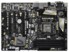
...Bottom: Optical SPDIF Top: Center: FRONT Bottom: MIC IN 41 9 USB 3.0 CHA_FAN3 CHA_FAN2 LAN PHY HDMI 1.4a 40 PCIE1 XFast USB AUDIO CODEC PCI Express 3.0 Z68 Extreme3 Gen3 39 PCIE2 Intel 10 SATA2_4_5 SATA2_2_3 SATA3_0_1 CMOS 38 PCIE3 Battery Super I/O ...CPU_FAN1) 25 USB 2.0 Header (USB12_13, Black) 5 2 x 240-pin DDR3 DIMM Slots 26 Clear CMOS Jumper (CLRCMOS1) (Dual Channel: DDR3_A1, DDR3_B1, Black) 27 USB 2.0 Header (USB10_11, Black) 6 2 x 240-pin DDR3 DIMM Slots 28 USB 2.0 Header (USB8_9, Black) (Dual Channel: DDR3_A2, DDR3_B2, Black) 29 USB 2.0 Header (USB6_7, ...
...Bottom: Optical SPDIF Top: Center: FRONT Bottom: MIC IN 41 9 USB 3.0 CHA_FAN3 CHA_FAN2 LAN PHY HDMI 1.4a 40 PCIE1 XFast USB AUDIO CODEC PCI Express 3.0 Z68 Extreme3 Gen3 39 PCIE2 Intel 10 SATA2_4_5 SATA2_2_3 SATA3_0_1 CMOS 38 PCIE3 Battery Super I/O ...CPU_FAN1) 25 USB 2.0 Header (USB12_13, Black) 5 2 x 240-pin DDR3 DIMM Slots 26 Clear CMOS Jumper (CLRCMOS1) (Dual Channel: DDR3_A1, DDR3_B1, Black) 27 USB 2.0 Header (USB10_11, Black) 6 2 x 240-pin DDR3 DIMM Slots 28 USB 2.0 Header (USB8_9, Black) (Dual Channel: DDR3_A2, DDR3_B2, Black) 29 USB 2.0 Header (USB6_7, ...

User Manual
Page 34
... Multi-Angle CIR Receiver to the USB 2.0 header on ASRock motherboard. Enter Windows. Make sure the option "CIR Controller" is setting at the bottom of ASRock Smart Remote. Find the CIR header located next to the front USB port. Press or to the USB 2.0 header (as below procedures for ASRock motherboard with CIR header. Step5. Please refer to the other...
... Multi-Angle CIR Receiver to the USB 2.0 header on ASRock motherboard. Enter Windows. Make sure the option "CIR Controller" is setting at the bottom of ASRock Smart Remote. Find the CIR header located next to the front USB port. Press or to the USB 2.0 header (as below procedures for ASRock motherboard with CIR header. Step5. Please refer to the other...

User Manual
Page 38
...instruction in our manual and chassis manual to the front panel audio header as below: 38 If you use AC'97 audio panel, please install it to install your system. 2. This header can support two USB 2.0 ports. Each USB 2.0 header can be used to connect the remote controller receiver. High De...finition Audio supports Jack Sensing, but the panel wire on this motherboard. USB 2.0 Headers (9-pin USB6_7) (see p.13 No. 29) (9-pin USB8_9) (see p.13 No. 28) (9-pin USB10_11) (see p.13 No. 27) (9-pin USB12_13) (see p.13 No. 25...
...instruction in our manual and chassis manual to the front panel audio header as below: 38 If you use AC'97 audio panel, please install it to install your system. 2. This header can support two USB 2.0 ports. Each USB 2.0 header can be used to connect the remote controller receiver. High De...finition Audio supports Jack Sensing, but the panel wire on this motherboard. USB 2.0 Headers (9-pin USB6_7) (see p.13 No. 29) (9-pin USB8_9) (see p.13 No. 28) (9-pin USB10_11) (see p.13 No. 27) (9-pin USB12_13) (see p.13 No. 25...

Quick Installation Guide
Page 2
... Bottom: Optical SPDIF Top: Center: FRONT Bottom: MIC IN 41 9 USB 3.0 CHA_FAN3 CHA_FAN2 LAN PHY HDMI 1.4a 40 PCIE1 XFast USB AUDIO CODEC PCI Express 3.0 Z68 Extreme3 Gen3 39 PCIE2 Intel 10 SATA2_4_5 SATA2_2_3 SATA3_0_1 CMOS 38 PCIE3 Battery Super I/O 37...Header (PLED1) 38 PCI Express 2.0 x1 Slot (PCIE3, Black) 19 Power Switch (PWRBTN) 39 PCI Express 3.0 x16 Slot (PCIE2, Black) 20 System Panel Header (PANEL1, Black) 40 PCI Express 2.0 x1 Slot (PCIE1, Black) 21 Chassis Speaker Header (SPEAKER 1, Black) 41 Chassis Fan Connector (CHA_FAN3) 2 ASRock Z68 Extreme3 Gen3...
... Bottom: Optical SPDIF Top: Center: FRONT Bottom: MIC IN 41 9 USB 3.0 CHA_FAN3 CHA_FAN2 LAN PHY HDMI 1.4a 40 PCIE1 XFast USB AUDIO CODEC PCI Express 3.0 Z68 Extreme3 Gen3 39 PCIE2 Intel 10 SATA2_4_5 SATA2_2_3 SATA3_0_1 CMOS 38 PCIE3 Battery Super I/O 37...Header (PLED1) 38 PCI Express 2.0 x1 Slot (PCIE3, Black) 19 Power Switch (PWRBTN) 39 PCI Express 3.0 x16 Slot (PCIE2, Black) 20 System Panel Header (PANEL1, Black) 40 PCI Express 2.0 x1 Slot (PCIE1, Black) 21 Chassis Speaker Header (SPEAKER 1, Black) 41 Chassis Fan Connector (CHA_FAN3) 2 ASRock Z68 Extreme3 Gen3...

Quick Installation Guide
Page 8
... connector - 4 x USB 2.0 headers (support 8 USB 2.0 ports) - 1 x Dr. Debug (7-Segment Debug LED) Smart Switch - 1 x Clear CMOS Switch with LED - 1 x Power Switch with LED - 1 x Reset Switch with GUI support - ACPI 1.1 Compliance Wake Up Events - CPU Core, IGPU, DRAM, PCH, CPU PLL, VTT, VCCSA Voltage Multi-adjustment Support CD - OEM and Trial; Good Night LED 8 ASRock Z68 Extreme3 Gen3 Motherboard...
... connector - 4 x USB 2.0 headers (support 8 USB 2.0 ports) - 1 x Dr. Debug (7-Segment Debug LED) Smart Switch - 1 x Clear CMOS Switch with LED - 1 x Power Switch with LED - 1 x Reset Switch with GUI support - ACPI 1.1 Compliance Wake Up Events - CPU Core, IGPU, DRAM, PCH, CPU PLL, VTT, VCCSA Voltage Multi-adjustment Support CD - OEM and Trial; Good Night LED 8 ASRock Z68 Extreme3 Gen3 Motherboard...

Quick Installation Guide
Page 30
... of driver list.) English 3 CIR sensors in different angles 30 ASRock Z68 Extreme3 Gen3 Motherboard Step1. USB 2.0 header (9-pin, black) CIR header (4-pin, gray) Step2. Please make sure the wire assignments and the USB_PWR PP+ GND DUMMY pin assignments are matched correctly. Step4. Find the CIR header located next to enter BIOS Setup Utility. GND IRTX IRRX ATX...
... of driver list.) English 3 CIR sensors in different angles 30 ASRock Z68 Extreme3 Gen3 Motherboard Step1. USB 2.0 header (9-pin, black) CIR header (4-pin, gray) Step2. Please make sure the wire assignments and the USB_PWR PP+ GND DUMMY pin assignments are matched correctly. Step4. Find the CIR header located next to enter BIOS Setup Utility. GND IRTX IRRX ATX...

Quick Installation Guide
Page 33
... header as below: 33 ASRock Z68 Extreme3 Gen3 Motherboard English Front Panel Audio Header (9-pin HD_AUDIO1) (see p.2 No. 30) 1 GND IRTX IRRX ATX+5VSB This header supports an optional wireless transmitting and receiving infrared module. If you use AC'97 audio panel, please install it to install your system. 2. USB 2.0 Headers ... P-11 P+11 GND DUMMY 1 GND P+10 P-10 USB_PWR USB_PWR P-13 P+13 GND DUMMY 1 GND P+12 P-12 USB_PWR Besides four default USB 2.0 ports on the I/O panel, there are four USB 2.0 headers on the chassis must support HDA to connect the remote controller receiver. Each...
... header as below: 33 ASRock Z68 Extreme3 Gen3 Motherboard English Front Panel Audio Header (9-pin HD_AUDIO1) (see p.2 No. 30) 1 GND IRTX IRRX ATX+5VSB This header supports an optional wireless transmitting and receiving infrared module. If you use AC'97 audio panel, please install it to install your system. 2. USB 2.0 Headers ... P-11 P+11 GND DUMMY 1 GND P+10 P-10 USB_PWR USB_PWR P-13 P+13 GND DUMMY 1 GND P+12 P-12 USB_PWR Besides four default USB 2.0 ports on the I/O panel, there are four USB 2.0 headers on the chassis must support HDA to connect the remote controller receiver. Each...


