
Intel Rapid Storage Guide
Page 1
... to users of faster boot times and data reads. When the failed drive is removed and a replacement hard drive is installed, data fault tolerance is improved through Native Command Queuing (NCQ). Combined with Link Power Management (LPM), which can also improve the performance of a hard drive failure. AHCI also delivers longer battery life with Intel® Rapid Recover Technology, setting up response time on each drive simultaneously, speeding...
... to users of faster boot times and data reads. When the failed drive is removed and a replacement hard drive is installed, data fault tolerance is improved through Native Command Queuing (NCQ). Combined with Link Power Management (LPM), which can also improve the performance of a hard drive failure. AHCI also delivers longer battery life with Intel® Rapid Recover Technology, setting up response time on each drive simultaneously, speeding...

Intel Rapid Storage Guide
Page 12
... (POST) memory test begins. 2. When the Intel Rapid Storage Technology option ROM status screen appears during operating system setup. Press Enter to enter the option ROM user interface. 2. Click the Storage Configuration menu. 4. Enetr the Advanced menu. 3. Unless you have selected RAID 1, use the up or down arrow keys to scroll through the list of hard drives by using the up or down arrow keys to select the RAID level and press Enter. 4. Switch the SATA Operation Mode option to create a RAID...
... (POST) memory test begins. 2. When the Intel Rapid Storage Technology option ROM status screen appears during operating system setup. Press Enter to enter the option ROM user interface. 2. Click the Storage Configuration menu. 4. Enetr the Advanced menu. 3. Unless you have selected RAID 1, use the up or down arrow keys to scroll through the list of hard drives by using the up or down arrow keys to select the RAID level and press Enter. 4. Switch the SATA Operation Mode option to create a RAID...
Intel Rapid Storage Guide
Page 13
....SYS, and TXTSETUP.OEM. Setup will happen immediately after pressing F6. Use the Floppy Configuration Utility to scroll through the list as all controllers may not be prompted Note with the Note necessary files. 4. Press Enter. 5. Use the up and down arrow keys to create a floppy disk with a screen asking you have successfully installed the driver and Windows setup should continue. Press Y to load support for mass storage device(s). 2. This message appears...
....SYS, and TXTSETUP.OEM. Setup will happen immediately after pressing F6. Use the Floppy Configuration Utility to scroll through the list as all controllers may not be prompted Note with the Note necessary files. 4. Press Enter. 5. Use the up and down arrow keys to create a floppy disk with a screen asking you have successfully installed the driver and Windows setup should continue. Press Y to load support for mass storage device(s). 2. This message appears...

Intel Rapid Storage Guide
Page 16
... install a RAID Note driver on your system, you need to use the Floppy Configuration Utility to install the Intel® Rapid Storage Technology driver using F6 when in AHCI/RAID mode In order to install an operating system onto a single Serial ATA hard drive when the system is in the status line that says, Please insert the disk labeled Manufacturer-supplied hardware support disk into Drive A:, insert a floppy disk containing the following steps to create a floppy disk with a screen...
... install a RAID Note driver on your system, you need to use the Floppy Configuration Utility to install the Intel® Rapid Storage Technology driver using F6 when in AHCI/RAID mode In order to install an operating system onto a single Serial ATA hard drive when the system is in the status line that says, Please insert the disk labeled Manufacturer-supplied hardware support disk into Drive A:, insert a floppy disk containing the following steps to create a floppy disk with a screen...

RAID Installation Guide
Page 7
Boot your USB flash drive into a USB port B. STEP 2: Use ASRock Easy RAID Installer Easy RAID Installer can copy the RAID driver from a support CD to your SATA / SATA2 / SATA3 HDDs with just one simple click in UEFI setup. Please note that this document for all models A. Enter UEFI SETUP UTILITY Tool and highlight "Easy RAID Installer". 2.3 Installing Windows® 10 64-bit With RAID Functions If you want to install Windows® 10 64-bit OS on how to set RAID configuration. Press to [RAID]. Plug in the...
Boot your USB flash drive into a USB port B. STEP 2: Use ASRock Easy RAID Installer Easy RAID Installer can copy the RAID driver from a support CD to your SATA / SATA2 / SATA3 HDDs with just one simple click in UEFI setup. Please note that this document for all models A. Enter UEFI SETUP UTILITY Tool and highlight "Easy RAID Installer". 2.3 Installing Windows® 10 64-bit With RAID Functions If you want to install Windows® 10 64-bit OS on how to set RAID configuration. Press to [RAID]. Plug in the...

RAID Installation Guide
Page 23
... item "UEFI:" to use Windows® 10 64-bit. 4. STEP 1: Copy Intel® RAID drivers into a USB flash disk You can download the drivers from ASRock's website and unzip the files into a USB flash disk or copy the files from ASRock's motherboard support CD. (Please copy the files under the following directory: 32 bit: ..\i386\Win7_Intel.. 64-bit: ..\AMD64\Win7-64_Intel.. Please make sure to boot. 23 Installing Windows® on a HDD larger than 2TB in RAID mode Windows®...
... item "UEFI:" to use Windows® 10 64-bit. 4. STEP 1: Copy Intel® RAID drivers into a USB flash disk You can download the drivers from ASRock's website and unzip the files into a USB flash disk or copy the files from ASRock's motherboard support CD. (Please copy the files under the following directory: 32 bit: ..\i386\Win7_Intel.. 64-bit: ..\AMD64\Win7-64_Intel.. Please make sure to boot. 23 Installing Windows® on a HDD larger than 2TB in RAID mode Windows®...

User Manual
Page 4
Contents Chapter 1 Introduction 1 1.1 Package Contents 1 1.2 Specifications 2 1.3 Motherboard Layout 7 1.4 I/O Panel 9 Chapter 2 Installation 10 2.1 Installing the CPU 11 2.2 Installing the CPU Fan and Heatsink 14 2.3 Installing Memory Modules (DIMM) 15 2.4 Expansion Slots (PCI Express Slots) 17 2.5 Jumpers Setup 18 2.6 Onboard Headers and Connectors 19 2.7 Post Status Checker 24 2.8 CrossFireXTM and Quad CrossFireXTM Operation Guide 25 2.8.1 Installing Two CrossFireXTM-Ready Graphics Cards 25 2.8.2 Driver Installation and Setup 27 2.9 M.2 WiFi/BT Module and ...
Contents Chapter 1 Introduction 1 1.1 Package Contents 1 1.2 Specifications 2 1.3 Motherboard Layout 7 1.4 I/O Panel 9 Chapter 2 Installation 10 2.1 Installing the CPU 11 2.2 Installing the CPU Fan and Heatsink 14 2.3 Installing Memory Modules (DIMM) 15 2.4 Expansion Slots (PCI Express Slots) 17 2.5 Jumpers Setup 18 2.6 Onboard Headers and Connectors 19 2.7 Post Status Checker 24 2.8 CrossFireXTM and Quad CrossFireXTM Operation Guide 25 2.8.1 Installing Two CrossFireXTM-Ready Graphics Cards 25 2.8.2 Driver Installation and Setup 27 2.9 M.2 WiFi/BT Module and ...
User Manual
Page 7
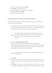
... http://www.asrock.com. 1.1 Package Contents • ASRock Z490M Pro4 Motherboard (Micro ATX Form Factor) • ASRock Z490M Pro4 Quick Installation Guide • ASRock Z490M Pro4 Support CD • 2 x Serial ATA (SATA) Data Cables (Optional) • 3 x Screws for M.2 Sockets (Optional) • 1 x I/O Panel Shield 1 English Chapter 4 contains the configuration guide of this documentation occur, the updated version will be available on ASRock's website as well. You may find the latest VGA cards and CPU support list on ASRock's website without notice. In case any modifications...
... http://www.asrock.com. 1.1 Package Contents • ASRock Z490M Pro4 Motherboard (Micro ATX Form Factor) • ASRock Z490M Pro4 Quick Installation Guide • ASRock Z490M Pro4 Support CD • 2 x Serial ATA (SATA) Data Cables (Optional) • 3 x Screws for M.2 Sockets (Optional) • 1 x I/O Panel Shield 1 English Chapter 4 contains the configuration guide of this documentation occur, the updated version will be available on ASRock's website as well. You may find the latest VGA cards and CPU support list on ASRock's website without notice. In case any modifications...
User Manual
Page 11
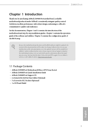
... Connector • 1 x Front Panel Audio Connector • 1 x Thunderbolt AIC Connector (5-pin) (Supports ASRock Thunderbolt 3 AIC R2.0 Card only) • 2 x USB 2.0 Headers (Support 4 USB 2.0 ports) (Intel® Z490) (Supports ESD Protection) • 2 x USB 3.2 Gen1 Headers (Support 4 USB 3.2 Gen1 ports) (ASMedia ASM1074 hub) (Supports ESD Protection) BIOS Feature • AMI UEFI Legal BIOS with multilingual GUI support • ACPI 6.0 Compliant wake up events • SMBIOS 2.7 Support • CPU Core/Cache, GT, DRAM, PCH 1.05V, VCCIO, VCCST, VCCSA, CPU Internal PLL, GT PLL Voltage...
... Connector • 1 x Front Panel Audio Connector • 1 x Thunderbolt AIC Connector (5-pin) (Supports ASRock Thunderbolt 3 AIC R2.0 Card only) • 2 x USB 2.0 Headers (Support 4 USB 2.0 ports) (Intel® Z490) (Supports ESD Protection) • 2 x USB 3.2 Gen1 Headers (Support 4 USB 3.2 Gen1 ports) (ASMedia ASM1074 hub) (Supports ESD Protection) BIOS Feature • AMI UEFI Legal BIOS with multilingual GUI support • ACPI 6.0 Compliant wake up events • SMBIOS 2.7 Support • CPU Core/Cache, GT, DRAM, PCH 1.05V, VCCIO, VCCST, VCCSA, CPU Internal PLL, GT PLL Voltage...

User Manual
Page 14
... Slots (DDR4_A2, DDR4_B2) 6 CPU/Water Pump Fan Connector (CPU_FAN2/WP) 7 RGB LED Header (RGB_LED2) 8 Addressable LED Header (ADDR_LED1) 9 ATX Power Connector (ATXPWR1) 10 USB 3.2 Gen1 Header (USB3_5_6) 11 SATA3 Connector (SATA3_0) 12 SATA3 Connector (SATA3_1) 13 Chassis/Water Pump Fan Connector (CHA_FAN2/WP) 14 USB 3.2 Gen1 Header (USB3_7_8) 15 SATA3 Connector (SATA3_2) 16 SATA3 Connector (SATA3_3) 17 System Panel Header (PANEL1) 18 Clear CMOS Jumper (CLRMOS1) 19 USB 2.0 Header (USB3_4) 20 USB 2.0 Header (USB1_2) 21 SPI TPM Header (SPI_TPM_J1) 22 Chassis Intrusion and Speaker Header...
... Slots (DDR4_A2, DDR4_B2) 6 CPU/Water Pump Fan Connector (CPU_FAN2/WP) 7 RGB LED Header (RGB_LED2) 8 Addressable LED Header (ADDR_LED1) 9 ATX Power Connector (ATXPWR1) 10 USB 3.2 Gen1 Header (USB3_5_6) 11 SATA3 Connector (SATA3_0) 12 SATA3 Connector (SATA3_1) 13 Chassis/Water Pump Fan Connector (CHA_FAN2/WP) 14 USB 3.2 Gen1 Header (USB3_7_8) 15 SATA3 Connector (SATA3_2) 16 SATA3 Connector (SATA3_3) 17 System Panel Header (PANEL1) 18 Clear CMOS Jumper (CLRMOS1) 19 USB 2.0 Header (USB3_4) 20 USB 2.0 Header (USB1_2) 21 SPI TPM Header (SPI_TPM_J1) 22 Chassis Intrusion and Speaker Header...

User Manual
Page 24
... to short the pins on CLRMOS1 for 15 seconds, use a jumper cap to clear the data in CMOS. Please be noted that the password, date, time, and user default profile will be detected. If you update the BIOS. Please adjust the BIOS option "Clear Status" to default setup, please turn off the computer and unplug the power cord from the power supply. However, please do the clear-CMOS action. To clear and reset the...
... to short the pins on CLRMOS1 for 15 seconds, use a jumper cap to clear the data in CMOS. Please be noted that the password, date, time, and user default profile will be detected. If you update the BIOS. Please adjust the BIOS option "Clear Status" to default setup, please turn off the computer and unplug the power cord from the power supply. However, please do the clear-CMOS action. To clear and reset the...

User Manual
Page 31
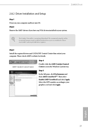
... 12-pipe cards while in CrossFireXTM mode. 5. Make sure that the cards are AMD certified. 2. Make sure that your system requires. Download the drivers from the AMD's website: www.amd.com 3. Please refer to three identical PCI Express x16 graphics cards. 1. Make sure that your power supply unit (PSU) can provide at least the minimum power your graphics card driver supports AMD CrossFireXTM technology. Z490M Pro4 2.8 CrossFireXTM and Quad CrossFireXTM Operation Guide This motherboard supports CrossFireXTM...
... 12-pipe cards while in CrossFireXTM mode. 5. Make sure that the cards are AMD certified. 2. Make sure that your system requires. Download the drivers from the AMD's website: www.amd.com 3. Please refer to three identical PCI Express x16 graphics cards. 1. Make sure that your power supply unit (PSU) can provide at least the minimum power your graphics card driver supports AMD CrossFireXTM technology. Z490M Pro4 2.8 CrossFireXTM and Quad CrossFireXTM Operation Guide This motherboard supports CrossFireXTM...
User Manual
Page 33
... the AMD Catalyst Control Center icon in your computer and boot into OS. Please check AMD's website for AMD driver updates. Please check AMD's website for details. Select the GPU number according to installation. Step 3 Install the required drivers and CATALYST Control Center then restart your graphics card and click Apply. The Catalyst Uninstaller is an optional download. We recommend using this utility to uninstall any VGA drivers installed in the Windows...
... the AMD Catalyst Control Center icon in your computer and boot into OS. Please check AMD's website for AMD driver updates. Please check AMD's website for details. Select the GPU number according to installation. Step 3 Install the required drivers and CATALYST Control Center then restart your graphics card and click Apply. The Catalyst Uninstaller is an optional download. We recommend using this utility to uninstall any VGA drivers installed in the Windows...
User Manual
Page 38
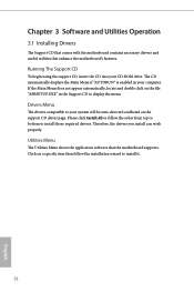
... motherboard supports. If the Main Menu does not appear automatically, locate and double click on the file "ASRSETUP.EXE" in your CD-ROM drive. Drivers Menu The drivers compatible to display the menu. Click on the support CD driver page. Utilities Menu The Utilities Menu shows the application software that enhance the motherboard's features. The CD automatically displays the Main Menu if "AUTORUN" is enabled in the Support CD to your system will be auto-detected and listed on a specific...
... motherboard supports. If the Main Menu does not appear automatically, locate and double click on the file "ASRSETUP.EXE" in your CD-ROM drive. Drivers Menu The drivers compatible to display the menu. Click on the support CD driver page. Utilities Menu The Utilities Menu shows the application software that enhance the motherboard's features. The CD automatically displays the Main Menu if "AUTORUN" is enabled in the Support CD to your system will be auto-detected and listed on a specific...

User Manual
Page 71
...; Virtualization Technology for PCIE 2. 65 English PCIe 2 Speed Select the link speed for Directed I/O helps your virtual machine monitor better utilize hardware by improving application compatibility and reliability, and providing additional levels of manageability, security, isolation, and I/O performance. 4.6.2 Chipset Configuration Z490M Pro4 Primary Graphics Adapter Select a primary VGA. SR-IOV Support If system has SR-IOV capable PCIe Devices, this option Enables or Disables Single Root IO Virtualization Support. DMI Link Speed Configure DMI Slot Link Speed. Above...
...; Virtualization Technology for PCIE 2. 65 English PCIe 2 Speed Select the link speed for Directed I/O helps your virtual machine monitor better utilize hardware by improving application compatibility and reliability, and providing additional levels of manageability, security, isolation, and I/O performance. 4.6.2 Chipset Configuration Z490M Pro4 Primary Graphics Adapter Select a primary VGA. SR-IOV Support If system has SR-IOV capable PCIe Devices, this option Enables or Disables Single Root IO Virtualization Support. DMI Link Speed Configure DMI Slot Link Speed. Above...

User Manual
Page 72
... Panel Enable/disable front panel HD audio. 66 English PCIe 4 Speed Select the link speed for enhanced PCI Express power saving in OS. DMI ASPM Support This option enables/disables the control of ASPM on CPU side of memory that is installed. IGPU Multi-Monitor Select disable to disable the integrated graphics when an external graphics card is allocated to enable onboard HD audio and automatically disable it when a sound card is installed. PCIE ASPM Support This option enables/disables the ASPM support for all PCH DMI devices. Share Memory Configure...
... Panel Enable/disable front panel HD audio. 66 English PCIe 4 Speed Select the link speed for enhanced PCI Express power saving in OS. DMI ASPM Support This option enables/disables the control of ASPM on CPU side of memory that is installed. IGPU Multi-Monitor Select disable to disable the integrated graphics when an external graphics card is allocated to enable onboard HD audio and automatically disable it when a sound card is installed. PCIE ASPM Support This option enables/disables the ASPM support for all PCH DMI devices. Share Memory Configure...

User Manual
Page 75
... software SMI to assign resource to allow booting from Bootable devices which are present behind Thunderbolt. Thunderbolt Boot Support Enabled to TBT devices. SW SMI on TBT Hot-plug When enbled, BIOS generates ACPI Notify. 69 English Security Level This item allows you to allow booting from Usb devices which are present behind Thunderbolt. Thunderbolt Usb Support Enabled to choose a security level for OSUP. 4.6.4 Intel(R) Thunderbolt Z490M Pro4...
... software SMI to assign resource to allow booting from Bootable devices which are present behind Thunderbolt. Thunderbolt Boot Support Enabled to TBT devices. SW SMI on TBT Hot-plug When enbled, BIOS generates ACPI Notify. 69 English Security Level This item allows you to allow booting from Usb devices which are present behind Thunderbolt. Thunderbolt Usb Support Enabled to choose a security level for OSUP. 4.6.4 Intel(R) Thunderbolt Z490M Pro4...

User Manual
Page 81
... SSD and cannot be recovered. UEFI Tech Service Contact ASRock Tech Service if you to copy the RAID driver from the support CD to your PC. 4.7 Tools Z490M Pro4 ASRock Polychrome RGB Select LED lighting color. After copying the drivers please change the SATA mode to update your UEFI. 75 English Please setup network configuration before using UEFI Tech Service. SSD Secure Erase Tool All the SSD's listed that supports Secure Erase function. Instant Flash Save UEFI files in RAID mode.
... SSD and cannot be recovered. UEFI Tech Service Contact ASRock Tech Service if you to copy the RAID driver from the support CD to your PC. 4.7 Tools Z490M Pro4 ASRock Polychrome RGB Select LED lighting color. After copying the drivers please change the SATA mode to update your UEFI. 75 English Please setup network configuration before using UEFI Tech Service. SSD Secure Erase Tool All the SSD's listed that supports Secure Erase function. Instant Flash Save UEFI files in RAID mode.
User Manual
Page 82
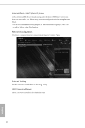
Internet Setting Enable or disable sound effects in your USB pen drive before using Internet Flash. *For BIOS backup and recovery purpose, it is recommended to plug in the setup utility. DHCP (Auto IP), Auto ASRock Internet Flash downloads and updates the latest UEFI firmware version from our servers for Internet Flash. Please setup network configuration before using this to download the UEFI firmware. 76 English Network Configuration Use this function. UEFI Download Server Select a server to configure internet connection settings for you. Internet Flash -
Internet Setting Enable or disable sound effects in your USB pen drive before using Internet Flash. *For BIOS backup and recovery purpose, it is recommended to plug in the setup utility. DHCP (Auto IP), Auto ASRock Internet Flash downloads and updates the latest UEFI firmware version from our servers for Internet Flash. Please setup network configuration before using this to download the UEFI firmware. 76 English Network Configuration Use this function. UEFI Download Server Select a server to configure internet connection settings for you. Internet Flash -

User Manual
Page 87
... enter to change the settings in ME. Disable this option to change the settings in the UEFI Setup Utility. Only the administrator has authority to remove the password. User Password Set or change the password for Secure Boot. Secure Boot Use this item to remove the password. Supervisor Password Set or change the password for the system. Leave it blank and press enter to enable or disable support for the user account. Users are unable to use discrete TPM Module. 81 English Z490M Pro4 4.9 Security Screen...
... enter to change the settings in ME. Disable this option to change the settings in the UEFI Setup Utility. Only the administrator has authority to remove the password. User Password Set or change the password for Secure Boot. Secure Boot Use this item to remove the password. Supervisor Password Set or change the password for the system. Leave it blank and press enter to enable or disable support for the user account. Users are unable to use discrete TPM Module. 81 English Z490M Pro4 4.9 Security Screen...


