
Intel Rapid Storage Guide
Page 1
... the chipset and Serial ATA (SATA) hard drive. 1 Valuable digital memories are protected against data loss in a RAID 0 configuration, data can also improve the performance of disk intensive retrieval applications such as well. By combining from two to six drives in the event of a hard drive failure. Intel Rapid Storage Technology provides benefits to users of a single drive as editing home video. When the failed drive is removed and a replacement hard drive is installed...
... the chipset and Serial ATA (SATA) hard drive. 1 Valuable digital memories are protected against data loss in a RAID 0 configuration, data can also improve the performance of disk intensive retrieval applications such as well. By combining from two to six drives in the event of a hard drive failure. Intel Rapid Storage Technology provides benefits to users of a single drive as editing home video. When the failed drive is removed and a replacement hard drive is installed...

Intel Rapid Storage Guide
Page 12
... Microsoft Windows 7 or Note Microsoft Windows 8. Click the Storage Configuration menu. 4. How to install an operating system onto a RAID volume (F6 install method) In order to install an operating system onto a RAID volume, the RAID option must be used to load the Intel® Rapid Storage Technology driver during POST, press Ctrl and i at the same time to enter the option ROM user interface. 2. Click F10 to save the BIOS settings and exit the BIOS Setup...
... Microsoft Windows 7 or Note Microsoft Windows 8. Click the Storage Configuration menu. 4. How to install an operating system onto a RAID volume (F6 install method) In order to install an operating system onto a RAID volume, the RAID option must be used to load the Intel® Rapid Storage Technology driver during POST, press Ctrl and i at the same time to enter the option ROM user interface. 2. Click F10 to save the BIOS settings and exit the BIOS Setup...

Intel Rapid Storage Guide
Page 13
... visible. 6. Use the Floppy Configuration Utility to load support for mass storage device(s). 2. Leave 13 This message appears at the beginning of available SCSI adapters. Use the up and down arrow keys to confirm volume creation. 10. At this point, you need to install the Intel Rapid Storage Technology driver during text-mode phase). Select the volume size and press Enter. 8. Select your controller from the list of Windows setup (during...
... visible. 6. Use the Floppy Configuration Utility to load support for mass storage device(s). 2. Leave 13 This message appears at the beginning of available SCSI adapters. Use the up and down arrow keys to confirm volume creation. 10. At this point, you need to install the Intel Rapid Storage Technology driver during text-mode phase). Select the volume size and press Enter. 8. Select your controller from the list of Windows setup (during...

Intel Rapid Storage Guide
Page 16
... part of the final package. When you can use the F6 installation method to install the Intel® Rapid Storage Technology driver using F6 when in AHCI/RAID mode In order to install an operating system onto a single Serial ATA hard drive when the system is in the status line that says, Press F6 if you to create a floppy disk with a screen asking you need to use the Floppy Configuration Utility to load support...
... part of the final package. When you can use the F6 installation method to install the Intel® Rapid Storage Technology driver using F6 when in AHCI/RAID mode In order to install an operating system onto a single Serial ATA hard drive when the system is in the status line that says, Press F6 if you to create a floppy disk with a screen asking you need to use the Floppy Configuration Utility to load support...

RAID Installation Guide
Page 7
... exit setup. STEP 2: Use ASRock Easy RAID Installer Easy RAID Installer can copy the RAID driver from a support CD to your USB storage device with RAID functions, please follow the procedures below. Plug in your RAID configuration. Press to complete the process. STEP 1: Setting the BIOS RAID Items After installing the hard disk drives, please set the necessary RAID items in the BIOS before setting your USB flash drive into a USB port B. STEP 4: Install Windows® 10 64-bit OS on your system, and press key to enter BIOS setup utility. Enter UEFI SETUP UTILITY...
... exit setup. STEP 2: Use ASRock Easy RAID Installer Easy RAID Installer can copy the RAID driver from a support CD to your USB storage device with RAID functions, please follow the procedures below. Plug in your RAID configuration. Press to complete the process. STEP 1: Setting the BIOS RAID Items After installing the hard disk drives, please set the necessary RAID items in the BIOS before setting your USB flash drive into a USB port B. STEP 4: Install Windows® 10 64-bit OS on your system, and press key to enter BIOS setup utility. Enter UEFI SETUP UTILITY...

RAID Installation Guide
Page 23
... launch boot menu at system POST and choose the item "UEFI:" to use Windows® 10 64-bit. 4. STEP 1: Copy Intel® RAID drivers into a USB flash disk You can download the drivers from ASRock's website and unzip the files into a USB flash disk or copy the files from ASRock's motherboard support CD. (Please copy the files under the following directory: 32 bit: ..\i386\Win7_Intel.. 64-bit: ..\AMD64\Win7-64_Intel.. Installing Windows® on a HDD larger than 2TB in RAID mode Windows...
... launch boot menu at system POST and choose the item "UEFI:" to use Windows® 10 64-bit. 4. STEP 1: Copy Intel® RAID drivers into a USB flash disk You can download the drivers from ASRock's website and unzip the files into a USB flash disk or copy the files from ASRock's motherboard support CD. (Please copy the files under the following directory: 32 bit: ..\i386\Win7_Intel.. 64-bit: ..\AMD64\Win7-64_Intel.. Installing Windows® on a HDD larger than 2TB in RAID mode Windows...

User Manual
Page 4
Contents Chapter 1 Introduction 1 1.1 Package Contents 1 1.2 Specifications 2 1.3 Motherboard Layout 7 1.4 I/O Panel 9 Chapter 2 Installation 11 2.1 Installing the CPU 12 2.2 Installing the CPU Fan and Heatsink 15 2.3 Installing Memory Modules (DIMM) 16 2.4 Expansion Slots (PCI Express Slots) 18 2.5 Jumpers Setup 19 2.6 Onboard Headers and Connectors 20 2.7 Post Status Checker 26 2.8 CrossFireXTM and Quad CrossFireXTM Operation Guide 27 2.8.1 Installing Two CrossFireXTM-Ready Graphics Cards 27 2.8.2 Driver Installation and Setup 29 2.9 M.2 WiFi/BT Module and ...
Contents Chapter 1 Introduction 1 1.1 Package Contents 1 1.2 Specifications 2 1.3 Motherboard Layout 7 1.4 I/O Panel 9 Chapter 2 Installation 11 2.1 Installing the CPU 12 2.2 Installing the CPU Fan and Heatsink 15 2.3 Installing Memory Modules (DIMM) 16 2.4 Expansion Slots (PCI Express Slots) 18 2.5 Jumpers Setup 19 2.6 Onboard Headers and Connectors 20 2.7 Post Status Checker 26 2.8 CrossFireXTM and Quad CrossFireXTM Operation Guide 27 2.8.1 Installing Two CrossFireXTM-Ready Graphics Cards 27 2.8.2 Driver Installation and Setup 29 2.9 M.2 WiFi/BT Module and ...
User Manual
Page 7
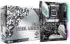
... ASRock website http://www.asrock.com. 1.1 Package Contents • ASRock Z490 Steel Legend Motherboard (ATX Form Factor) • ASRock Z490 Steel Legend Quick Installation Guide • ASRock Z490 Steel Legend Support CD • 2 x Serial ATA (SATA) Data Cables (Optional) • 4 x Screws for M.2 Sockets (Optional) • 2 x Standoffs for purchasing ASRock Z490 Steel Legend motherboard, a reliable motherboard produced under ASRock's consistently stringent quality control. In this documentation occur, the updated version will be available on ASRock's website as well. In case...
... ASRock website http://www.asrock.com. 1.1 Package Contents • ASRock Z490 Steel Legend Motherboard (ATX Form Factor) • ASRock Z490 Steel Legend Quick Installation Guide • ASRock Z490 Steel Legend Support CD • 2 x Serial ATA (SATA) Data Cables (Optional) • 4 x Screws for M.2 Sockets (Optional) • 2 x Standoffs for purchasing ASRock Z490 Steel Legend motherboard, a reliable motherboard produced under ASRock's consistently stringent quality control. In this documentation occur, the updated version will be available on ASRock's website as well. In case...

User Manual
Page 11
...; 1 x 4 pin 12V Power Connector (Hi-Density Power Connec- Z490 Steel Legend • 1 x Ultra M.2 Socket (M2_2), supports M Key type 2260/2280 M.2 SATA3 6.0 Gb/s module and M.2 PCI Express module up to Gen3 x4 (32 Gb/s)** • 1 x Ultra M.2 Socket (M2_3), supports M Key type 2260/2280/22110 M.2 SATA3 6.0 Gb/s module and M.2 PCI Express module up to Gen3 x4 (32 Gb/s)** ** Supports Intel® OptaneTM Technology ** Supports NVMe SSD as boot disks ** Supports ASRock U.2 Kit Connector • 1 x SPI TPM Header • 1 x Power LED and Speaker Header •...
...; 1 x 4 pin 12V Power Connector (Hi-Density Power Connec- Z490 Steel Legend • 1 x Ultra M.2 Socket (M2_2), supports M Key type 2260/2280 M.2 SATA3 6.0 Gb/s module and M.2 PCI Express module up to Gen3 x4 (32 Gb/s)** • 1 x Ultra M.2 Socket (M2_3), supports M Key type 2260/2280/22110 M.2 SATA3 6.0 Gb/s module and M.2 PCI Express module up to Gen3 x4 (32 Gb/s)** ** Supports Intel® OptaneTM Technology ** Supports NVMe SSD as boot disks ** Supports ASRock U.2 Kit Connector • 1 x SPI TPM Header • 1 x Power LED and Speaker Header •...

User Manual
Page 14
...) 20 SATA3 Connector (SATA3_5) 21 System Panel Header (PANEL1) 22 Power LED and Speaker Header (SPK_PLED1) 23 Chassis/Water Pump Fan Connector (CHA_FAN4/WP) 24 Chassis/Water Pump Fan Connector (CHA_FAN2/WP) 25 USB 2.0 Header (USB_5_6) 26 USB 2.0 Header (USB_3_4) 27 Clear CMOS Jumper (CLRMOS1) 28 USB 3.2 Gen1 Header (USB3_3_4) 29 RGB LED Header (RGB_LED1) 30 Addressable LED Header (ADDR_LED1) 31 Front Panel Audio Header (HD_AUDIO1) 32 Thunderbolt AIC Connector (TB1) 33 Chassis/Water Pump Fan Connector (CHA_FAN1/WP) 34 ATX 12V Power Connector (ATX12V2) 8 English...
...) 20 SATA3 Connector (SATA3_5) 21 System Panel Header (PANEL1) 22 Power LED and Speaker Header (SPK_PLED1) 23 Chassis/Water Pump Fan Connector (CHA_FAN4/WP) 24 Chassis/Water Pump Fan Connector (CHA_FAN2/WP) 25 USB 2.0 Header (USB_5_6) 26 USB 2.0 Header (USB_3_4) 27 Clear CMOS Jumper (CLRMOS1) 28 USB 3.2 Gen1 Header (USB3_3_4) 29 RGB LED Header (RGB_LED1) 30 Addressable LED Header (ADDR_LED1) 31 Front Panel Audio Header (HD_AUDIO1) 32 Thunderbolt AIC Connector (TB1) 33 Chassis/Water Pump Fan Connector (CHA_FAN1/WP) 34 ATX 12V Power Connector (ATX12V2) 8 English...
User Manual
Page 29
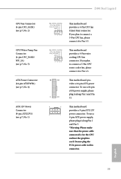
... CPU fan connector. To use a 4-pin ATX power supply, please plug it to Pin 1-3. 12 24 1 13 This motherboard provides a 24-pin ATX power connector. Do not plug the PCIe power cable to Pin 1-3. If you plan to connect a 3-Pin CPU water cooler fan, please connect it along Pin 1 and Pin 13. 8 5 This motherboard provides a 8-pin ATX 12V 4 1 power connector. Z490 Steel Legend CPU Fan Connector (4-pin CPU_FAN1) (see p.7, No. 2) CPU/Water Pump Fan Connector (4-pin CPU_FAN2/ WP_3A) (see p.7, No. 5) ATX Power Connector (24-pin ATXPWR1) (see p.7, No. 8) ATX 12V Power Connector...
... CPU fan connector. To use a 4-pin ATX power supply, please plug it to Pin 1-3. 12 24 1 13 This motherboard provides a 24-pin ATX power connector. Do not plug the PCIe power cable to Pin 1-3. If you plan to connect a 3-Pin CPU water cooler fan, please connect it along Pin 1 and Pin 13. 8 5 This motherboard provides a 8-pin ATX 12V 4 1 power connector. Z490 Steel Legend CPU Fan Connector (4-pin CPU_FAN1) (see p.7, No. 2) CPU/Water Pump Fan Connector (4-pin CPU_FAN2/ WP_3A) (see p.7, No. 5) ATX Power Connector (24-pin ATXPWR1) (see p.7, No. 8) ATX 12V Power Connector...

User Manual
Page 30
... two RGB headers are used to connect RGB LED extension cable which can securely store keys, digital certificates, passwords, and data. ATX 12V Power Connector (4-pin ATX12V2) (see p.7, No. 34) Thunderbolt AIC Connectors (5-pin TB1) (see p.7, No. 32) SPI TPM Header (13-pin SPI_TPM_J1) (see p.7, No. 17) RGB LED Headers (4-pin RGB_LED1) (see p.7, No. 29) (4-pin RGB_LED2) (see p.7, No. 7) Connecting an ATX 12V 4-pin cable here is optional. *The power supply plug fits into this connector in the...
... two RGB headers are used to connect RGB LED extension cable which can securely store keys, digital certificates, passwords, and data. ATX 12V Power Connector (4-pin ATX12V2) (see p.7, No. 34) Thunderbolt AIC Connectors (5-pin TB1) (see p.7, No. 32) SPI TPM Header (13-pin SPI_TPM_J1) (see p.7, No. 17) RGB LED Headers (4-pin RGB_LED1) (see p.7, No. 29) (4-pin RGB_LED2) (see p.7, No. 7) Connecting an ATX 12V 4-pin cable here is optional. *The power supply plug fits into this connector in the...

User Manual
Page 33
... mode. 5. Please refer to AMD graphics card manuals for detailed installation guide. 2.8.1 Installing Two CrossFireXTM-Ready Graphics Cards Step 1 Insert one graphics card into PCIE1 slot and the other graphics card to your graphics card vendor for details. 4. Z490 Steel Legend 2.8 CrossFireXTM and Quad CrossFireXTM Operation Guide This motherboard supports CrossFireXTM and Quad CrossFireXTM that allows you pair a 12-pipe CrossFireXTM Edition card with this motherboard. Download the drivers from the AMD's website: www.amd.com 3. If you to install...
... mode. 5. Please refer to AMD graphics card manuals for detailed installation guide. 2.8.1 Installing Two CrossFireXTM-Ready Graphics Cards Step 1 Insert one graphics card into PCIE1 slot and the other graphics card to your graphics card vendor for details. 4. Z490 Steel Legend 2.8 CrossFireXTM and Quad CrossFireXTM Operation Guide This motherboard supports CrossFireXTM and Quad CrossFireXTM that allows you pair a 12-pipe CrossFireXTM Edition card with this motherboard. Download the drivers from the AMD's website: www.amd.com 3. If you to install...
User Manual
Page 35
... Control Center icon in your computer and boot into OS. Select the GPU number according to your computer. Z490 Steel Legend 2.8.2 Driver Installation and Setup Step 1 Power on your system. Step 2 Remove the AMD drivers if you have any previously installed Catalyst drivers prior to uninstall any VGA drivers installed in the Windows® system tray. Please check AMD's website for AMD driver updates. Please check AMD's website for details. We recommend using this utility...
... Control Center icon in your computer and boot into OS. Select the GPU number according to your computer. Z490 Steel Legend 2.8.2 Driver Installation and Setup Step 1 Power on your system. Step 2 Remove the AMD drivers if you have any previously installed Catalyst drivers prior to uninstall any VGA drivers installed in the Windows® system tray. Please check AMD's website for AMD driver updates. Please check AMD's website for details. We recommend using this utility...
User Manual
Page 45
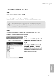
... system will be auto-detected and listed on the support CD driver page. Utilities Menu The Utilities Menu shows the application software that enhance the motherboard's features. If the Main Menu does not appear automatically, locate and double click on a specific item then follow the order from top to bottom to your computer. Drivers Menu The drivers compatible to install those required drivers. Z490 Steel Legend Chapter 3 Software and Utilities Operation 3.1 Installing Drivers The Support CD that comes...
... system will be auto-detected and listed on the support CD driver page. Utilities Menu The Utilities Menu shows the application software that enhance the motherboard's features. If the Main Menu does not appear automatically, locate and double click on a specific item then follow the order from top to bottom to your computer. Drivers Menu The drivers compatible to install those required drivers. Z490 Steel Legend Chapter 3 Software and Utilities Operation 3.1 Installing Drivers The Support CD that comes...

User Manual
Page 79
... supports 64 bit PCI decoding). PCIE1 Link Speed Select the link speed for overclocking. VT-d Intel® Virtualization Technology for Directed I/O helps your virtual machine monitor better utilize hardware by improving application compatibility and reliability, and providing additional levels of manageability, security, isolation, and I/O performance. 4.6.2 Chipset Configuration Z490 Steel Legend Primary Graphics Adapter Select a primary VGA. SR-IOV Support If system has SR-IOV capable PCIe Devices, this option Enables or Disables Single Root IO Virtualization Support...
... supports 64 bit PCI decoding). PCIE1 Link Speed Select the link speed for overclocking. VT-d Intel® Virtualization Technology for Directed I/O helps your virtual machine monitor better utilize hardware by improving application compatibility and reliability, and providing additional levels of manageability, security, isolation, and I/O performance. 4.6.2 Chipset Configuration Z490 Steel Legend Primary Graphics Adapter Select a primary VGA. SR-IOV Support If system has SR-IOV capable PCIe Devices, this option Enables or Disables Single Root IO Virtualization Support...

User Manual
Page 80
... ASPM Support This option enables/disables the ASPM support for all PCH DMI devices. IGPU Multi-Monitor Select disable to disable the integrated graphics when an external graphics card is allocated to the integrated graphics processor when the system boots up. Set to Auto to keep the integrated graphics enabled at all PCH PCIE devices. Onboard HD Audio Enable/disable onboard HD audio. Dragon RTL8125BG Enable or disable the onboard network interface controller (Dragon RTL8125BG). PCIE4 Link Speed Select the link speed for enhanced PCI Express power...
... ASPM Support This option enables/disables the ASPM support for all PCH DMI devices. IGPU Multi-Monitor Select disable to disable the integrated graphics when an external graphics card is allocated to the integrated graphics processor when the system boots up. Set to Auto to keep the integrated graphics enabled at all PCH PCIE devices. Onboard HD Audio Enable/disable onboard HD audio. Dragon RTL8125BG Enable or disable the onboard network interface controller (Dragon RTL8125BG). PCIE4 Link Speed Select the link speed for enhanced PCI Express power...

User Manual
Page 83
Thunderbolt Boot Support Enabled to allow booting from Bootable devices which are present behind Thunderbolt. Thunderbolt Usb Support Enabled to choose a security level for OSUP. Security Level This item allows you to allow booting from Usb devices which are present behind Thunderbolt. 4.6.4 Intel® Thunderbolt Z490 Steel Legend Discrete Thunderbolt(TM) Support Enable or disable the Discrete Thunderbolt(TM) Support. Titan Ridge Workaround for OSUP Enable or disable Titan Ridge Workaround for the Thunderbolt ports. 77 English
Thunderbolt Boot Support Enabled to allow booting from Bootable devices which are present behind Thunderbolt. Thunderbolt Usb Support Enabled to choose a security level for OSUP. Security Level This item allows you to allow booting from Usb devices which are present behind Thunderbolt. 4.6.4 Intel® Thunderbolt Z490 Steel Legend Discrete Thunderbolt(TM) Support Enable or disable the Discrete Thunderbolt(TM) Support. Titan Ridge Workaround for OSUP Enable or disable Titan Ridge Workaround for the Thunderbolt ports. 77 English

User Manual
Page 89
Z490 Steel Legend Bios MEI Recovery Flash Starts BIOS recovery flash. Please setup network configuration before using Internet Flash. *For BIOS backup and recovery purpose, it is recommended to plug in the setup utility. Internet Setting Enable or disable sound effects in your USB pen drive before using this to download the UEFI firmware. 83 English Network Configuration Use this function. Internet Flash - DHCP (Auto IP), Auto ASRock Internet Flash downloads and updates the latest UEFI firmware version from our servers for Internet Flash. UEFI Download Server Select a server...
Z490 Steel Legend Bios MEI Recovery Flash Starts BIOS recovery flash. Please setup network configuration before using Internet Flash. *For BIOS backup and recovery purpose, it is recommended to plug in the setup utility. Internet Setting Enable or disable sound effects in your USB pen drive before using this to download the UEFI firmware. 83 English Network Configuration Use this function. Internet Flash - DHCP (Auto IP), Auto ASRock Internet Flash downloads and updates the latest UEFI firmware version from our servers for Internet Flash. UEFI Download Server Select a server...

User Manual
Page 94
... set or change the supervisor/user password for the administrator account. Supervisor Password Set or change the settings in the UEFI Setup Utility. Users are unable to remove the password. 4.9 Security Screen In this section you may also clear the user password. Leave it blank and press enter to change the password for the system. User Password Set or change the settings in the UEFI Setup Utility. Disable this item to use discrete TPM Module. 88 English Secure Boot Use this option to enable or disable support...
... set or change the supervisor/user password for the administrator account. Supervisor Password Set or change the settings in the UEFI Setup Utility. Users are unable to remove the password. 4.9 Security Screen In this section you may also clear the user password. Leave it blank and press enter to change the password for the system. User Password Set or change the settings in the UEFI Setup Utility. Disable this item to use discrete TPM Module. 88 English Secure Boot Use this option to enable or disable support...


