
Intel Rapid Storage Guide
Page 12
... the up or down arrow keys to select the strip size and press Enter. 5. Enable RAID in System BIOS Use the instructions included with your motherboard to enable RAID in the system BIOS, a RAID volume must be created, and the F6 installation method must be used to load the Intel®...
... the up or down arrow keys to select the strip size and press Enter. 5. Enable RAID in System BIOS Use the instructions included with your motherboard to enable RAID in the system BIOS, a RAID volume must be created, and the F6 installation method must be used to load the Intel®...

RAID Installation Guide
Page 2
You may install SATA hard disks on SATA ports. 2 Guide to create RAID on this guide carefully according to the Intel southbridge chipset that your motherboard adopts. This section will guide you how to SATA Hard Disks Installation 1.1 Serial ATA (SATA) Hard Disks Installation Intel chipset supports Serial ATA (SATA) hard disks with RAID functions, including RAID 0, RAID 1, RAID 5, RAID 10 and Intel Rapid Storage. Please read the RAID configurations in this motherboard for internal storage devices. 1.
You may install SATA hard disks on SATA ports. 2 Guide to create RAID on this guide carefully according to the Intel southbridge chipset that your motherboard adopts. This section will guide you how to SATA Hard Disks Installation 1.1 Serial ATA (SATA) Hard Disks Installation Intel chipset supports Serial ATA (SATA) hard disks with RAID functions, including RAID 0, RAID 1, RAID 5, RAID 10 and Intel Rapid Storage. Please read the RAID configurations in this motherboard for internal storage devices. 1.

RAID Installation Guide
Page 3
... for "Redundant Array of Independent Disks", which is called data striping that optimizes two identical hard disk drives to RAID Configurations 2.1 Introduction of RAID This motherboard adopts Intel southbridge chipset that copies and maintains an identical image of the same model and capacity when creating a RAID set. Guide to read and...
... for "Redundant Array of Independent Disks", which is called data striping that optimizes two identical hard disk drives to RAID Configurations 2.1 Introduction of RAID This motherboard adopts Intel southbridge chipset that copies and maintains an identical image of the same model and capacity when creating a RAID set. Guide to read and...

RAID Installation Guide
Page 23
STEP 1: Copy Intel® RAID drivers into a USB flash disk You can download the drivers from ASRock's website and unzip the files into a USB flash disk or copy the files from ASRock's motherboard support CD. (Please copy the files under the following directory: 32 bit: ..\i386\Win7_Intel.. 64-bit: ..\AMD64\Win7-64_Intel.. Installing Windows...
STEP 1: Copy Intel® RAID drivers into a USB flash disk You can download the drivers from ASRock's website and unzip the files into a USB flash disk or copy the files from ASRock's motherboard support CD. (Please copy the files under the following directory: 32 bit: ..\i386\Win7_Intel.. 64-bit: ..\AMD64\Win7-64_Intel.. Installing Windows...

RAID Installation Guide
Page 25
...; >30 mins.) C. Please request the hotfix KB2505454 through this hotfix then reboot by itself. E. Windows® will need to follow the instructions below to install motherboard drivers and utilities. 25 After installing Windows® 10 64-bit, install the hotfix kb2505454. (This may take about 5 minutes to boot into Windows®...
...; >30 mins.) C. Please request the hotfix KB2505454 through this hotfix then reboot by itself. E. Windows® will need to follow the instructions below to install motherboard drivers and utilities. 25 After installing Windows® 10 64-bit, install the hotfix kb2505454. (This may take about 5 minutes to boot into Windows®...

User Manual
Page 2
... names appearing in this documentation may or may appear in Perchlorate Best Management Practices (BMP) regulations passed by ASRock. ASRock assumes no event shall ASRock, its directors, officers, employees, or agents be reproduced, transcribed, transmitted, or translated in any language, ..., including but not limited to the following two conditions: (1) this device may not cause harmful interference, and (2) this motherboard contains Perchlorate, a toxic substance controlled in this documentation may be liable for any interference received, including interference that may not...
... names appearing in this documentation may or may appear in Perchlorate Best Management Practices (BMP) regulations passed by ASRock. ASRock assumes no event shall ASRock, its directors, officers, employees, or agents be reproduced, transcribed, transmitted, or translated in any language, ..., including but not limited to the following two conditions: (1) this device may not cause harmful interference, and (2) this motherboard contains Perchlorate, a toxic substance controlled in this documentation may be liable for any interference received, including interference that may not...

User Manual
Page 5
Contents Chapter 1 Introduction 1 1.1 Package Contents 1 1.2 Specifications 2 1.3 Motherboard Layout 7 1.4 I/O Panel 9 1.5 WiFi-802.11ax Module and ASRock WiFi 2.4/5 GHz Antenna 10 Chapter 2 Installation 12 2.1 Installing the CPU 13 2.2 Installing the CPU Fan and Heatsink 16 2.3 Installing Memory Modules (DIMM) 17 2.4 Expansion Slots... 30 2.9 M.2 WiFi/BT Module Installation Guide 31 2.10 M.2_SSD (NGFF) Module Installation Guide (M2_2) 33 Chapter 3 Software and Utilities Operation 37 3.1 Installing Drivers 37 3.2 ASRock Motherboard Utility (Phantom Gaming Tuning) 38
Contents Chapter 1 Introduction 1 1.1 Package Contents 1 1.2 Specifications 2 1.3 Motherboard Layout 7 1.4 I/O Panel 9 1.5 WiFi-802.11ax Module and ASRock WiFi 2.4/5 GHz Antenna 10 Chapter 2 Installation 12 2.1 Installing the CPU 13 2.2 Installing the CPU Fan and Heatsink 16 2.3 Installing Memory Modules (DIMM) 17 2.4 Expansion Slots... 30 2.9 M.2 WiFi/BT Module Installation Guide 31 2.10 M.2_SSD (NGFF) Module Installation Guide (M2_2) 33 Chapter 3 Software and Utilities Operation 37 3.1 Installing Drivers 37 3.2 ASRock Motherboard Utility (Phantom Gaming Tuning) 38
User Manual
Page 9
... as well. If you for purchasing ASRock Z490 Phantom Gaming 4/ax motherboard, a reliable motherboard produced under ASRock's consistently stringent quality control. It delivers excellent performance with robust design conforming to ASRock's commitment to quality and endurance. ASRock website http://www.asrock.com. 1.1 Package Contents • ASRock Z490 Phantom Gaming 4/ax Motherboard (ATX Form Factor) • ASRock Z490 Phantom Gaming 4/ax Quick Installation Guide • ASRock Z490 Phantom Gaming 4/ax Support CD • 2 x Serial...
... as well. If you for purchasing ASRock Z490 Phantom Gaming 4/ax motherboard, a reliable motherboard produced under ASRock's consistently stringent quality control. It delivers excellent performance with robust design conforming to ASRock's commitment to quality and endurance. ASRock website http://www.asrock.com. 1.1 Package Contents • ASRock Z490 Phantom Gaming 4/ax Motherboard (ATX Form Factor) • ASRock Z490 Phantom Gaming 4/ax Quick Installation Guide • ASRock Z490 Phantom Gaming 4/ax Support CD • 2 x Serial...

User Manual
Page 15
HDMI1 USB 2.0 T: USB_1 B: USB_2 PS2 Keyboard /Mouse 1.3 Motherboard Layout 1 2 ATX12V1 ATX12V2 Z490 Phantom Gaming 4/ax 34 56 CPU_FAN1 CPU_FAN2/WP 7 ADDR_LED2 8 1 1 RGB_LED2 BOOT CPU 9 DRAM VGA DDR4_A1 (64 bit, 288-pin module) DDR4_A2 (64 bit,... B: USB31_TC_1 10 USB 3.2 Gen1 Top: T: USB3_1 B: USB3_2 RJ-45 CHA_FAN2/WP Top: LINE IN Center: FRONT Bottom: MIC IN PCIE1 32 Z490 PHANTOM GAMING 4/ax PCIE2 CHA_FAN1/WP USB3_3_4 11 1 12 13 SATA3_1 SATA3_0 M2_WIFI1 SUPER I/O WiFi-802.11ax M2_WIFI_CT1 Module 14 CMOS Battery Intel 15 SATA3_2 SATA3_3 PCIE3...
HDMI1 USB 2.0 T: USB_1 B: USB_2 PS2 Keyboard /Mouse 1.3 Motherboard Layout 1 2 ATX12V1 ATX12V2 Z490 Phantom Gaming 4/ax 34 56 CPU_FAN1 CPU_FAN2/WP 7 ADDR_LED2 8 1 1 RGB_LED2 BOOT CPU 9 DRAM VGA DDR4_A1 (64 bit, 288-pin module) DDR4_A2 (64 bit,... B: USB31_TC_1 10 USB 3.2 Gen1 Top: T: USB3_1 B: USB3_2 RJ-45 CHA_FAN2/WP Top: LINE IN Center: FRONT Bottom: MIC IN PCIE1 32 Z490 PHANTOM GAMING 4/ax PCIE2 CHA_FAN1/WP USB3_3_4 11 1 12 13 SATA3_1 SATA3_0 M2_WIFI1 SUPER I/O WiFi-802.11ax M2_WIFI_CT1 Module 14 CMOS Battery Intel 15 SATA3_2 SATA3_3 PCIE3...

User Manual
Page 18
... 2.4/5 GHz Antenna 10 English Bluetooth v5.1 standard features Smart Ready technology that offers support for PCs. 1.5 WiFi-802.11ax Module and ASRock WiFi 2.4/5 GHz Antenna WiFi-802.11ax + BT Module This motherboard comes with an exclusive WiFi 802.11 a/b/g/n/ax + BT v5.1 module that adds a whole new class of functionality into the...
... 2.4/5 GHz Antenna 10 English Bluetooth v5.1 standard features Smart Ready technology that offers support for PCs. 1.5 WiFi-802.11ax Module and ASRock WiFi 2.4/5 GHz Antenna WiFi-802.11ax + BT Module This motherboard comes with an exclusive WiFi 802.11 a/b/g/n/ax + BT v5.1 module that adds a whole new class of functionality into the...

User Manual
Page 20
... the configuration of the following precautions before installing or removing the motherboard components. Doing so may cause physical injuries and damages to motherboard components. • In order to avoid damage from static electricity to the motherboard's components, NEVER place your chassis to ensure that comes with the components. • When placing screws to...
... the configuration of the following precautions before installing or removing the motherboard components. Doing so may cause physical injuries and damages to motherboard components. • In order to avoid damage from static electricity to the motherboard's components, NEVER place your chassis to ensure that comes with the components. • When placing screws to...

User Manual
Page 23
The cover must be placed if you wish to return the motherboard for after service. 15 English Z490 Phantom Gaming 4/ax Please save and replace the cover if the processor is removed.
The cover must be placed if you wish to return the motherboard for after service. 15 English Z490 Phantom Gaming 4/ax Please save and replace the cover if the processor is removed.

User Manual
Page 25
Z490 Phantom Gaming 4/ax 2.3 Installing Memory Modules (DIMM) This motherboard provides four 288-pin DDR4 (Double Data Rate 4) DIMM slots, and supports Dual Channel Memory Technology. 1. It will cause permanent damage to the motherboard and the DIMM if you always need to install identical (the same brand, speed, size and chip-type) DDR4 DIMM pairs. 2....Priority 1 2 DDR4_A1 Populated DDR4_A2 Populated Populated DDR4_B1 Populated DDR4_B2 Populated Populated The DIMM only fits in one or three memory module installed. 3. otherwise, this motherboard and DIMM may be damaged. English 17
Z490 Phantom Gaming 4/ax 2.3 Installing Memory Modules (DIMM) This motherboard provides four 288-pin DDR4 (Double Data Rate 4) DIMM slots, and supports Dual Channel Memory Technology. 1. It will cause permanent damage to the motherboard and the DIMM if you always need to install identical (the same brand, speed, size and chip-type) DDR4 DIMM pairs. 2....Priority 1 2 DDR4_A1 Populated DDR4_A2 Populated Populated DDR4_B1 Populated DDR4_B2 Populated Populated The DIMM only fits in one or three memory module installed. 3. otherwise, this motherboard and DIMM may be damaged. English 17
User Manual
Page 27
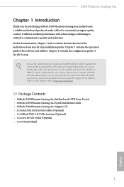
... PCIE2 x16 PCIE4 N/A Two Graphics Cards in CrossFireXTM Mode x16 x4 For a better thermal environment, please connect a chassis fan to the motherboard's chassis fan connector (CHA_FAN1/WP, CHA_FAN2/WP, CHA_FAN3/WP or CHA_FAN4/WP) when using multiple graphics cards. PCIE2 (PCIe 3.0 x16 slot... card, please make necessary hardware settings for PCI Express x16 lane width graphics cards. Z490 Phantom Gaming 4/ax 2.4 Expansion Slots (PCI Express Slots) There are 5 PCI Express slots on the motherboard. Please read the documentation of the expansion card and make sure that the power supply...
... PCIE2 x16 PCIE4 N/A Two Graphics Cards in CrossFireXTM Mode x16 x4 For a better thermal environment, please connect a chassis fan to the motherboard's chassis fan connector (CHA_FAN1/WP, CHA_FAN2/WP, CHA_FAN3/WP or CHA_FAN4/WP) when using multiple graphics cards. PCIE2 (PCIe 3.0 x16 slot... card, please make necessary hardware settings for PCI Express x16 lane width graphics cards. Z490 Phantom Gaming 4/ax 2.4 Expansion Slots (PCI Express Slots) There are 5 PCI Express slots on the motherboard. Please read the documentation of the expansion card and make sure that the power supply...
User Manual
Page 29
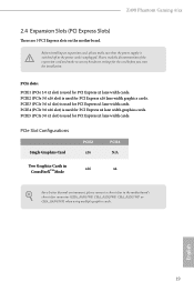
PWRBTN (Power Button): Connect to the power button on the chassis front panel. RESET (Reset Button): Connect to the motherboard. The LED keeps blinking when the system is reading or writing data. When connecting your system using the power button. English 21 Press ...drive activity LED on the chassis front panel. The LED is on when the hard drive is in S4 sleep state or powered off (S5). Z490 Phantom Gaming 4/ax 2.6 Onboard Headers and Connectors Onboard headers and connectors are matched correctly. Do NOT place jumper caps over the headers and connectors will cause...
PWRBTN (Power Button): Connect to the power button on the chassis front panel. RESET (Reset Button): Connect to the motherboard. The LED keeps blinking when the system is reading or writing data. When connecting your system using the power button. English 21 Press ...drive activity LED on the chassis front panel. The LED is on when the hard drive is in S4 sleep state or powered off (S5). Z490 Phantom Gaming 4/ax 2.6 Onboard Headers and Connectors Onboard headers and connectors are matched correctly. Do NOT place jumper caps over the headers and connectors will cause...

User Manual
Page 30
...) (see p.7, No. 20) SATA3_2 SATA3_0 SATA3_3 SATA3_1 SATA3_4 SATA3_5 These six SATA3 connectors support SATA data cables for internal storage devices with up to this motherboard. Each USB 2.0 header can support two ports. Please connect the chassis power LED and the chassis speaker to 6.0 Gb/s data transfer rate. * If M2_2 is...
...) (see p.7, No. 20) SATA3_2 SATA3_0 SATA3_3 SATA3_1 SATA3_4 SATA3_5 These six SATA3 connectors support SATA data cables for internal storage devices with up to this motherboard. Each USB 2.0 header can support two ports. Please connect the chassis power LED and the chassis speaker to 6.0 Gb/s data transfer rate. * If M2_2 is...
User Manual
Page 31
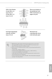
...3.2 Gen1 header can support two ports. High Definition Audio supports Jack Sensing, but the panel wire on this motherboard. Connect Mic_IN (MIC) to Ground (GND). E. Please follow the instructions in the Realtek Control panel and adjust... Vbus IntA_PA_SSRXIntA_PA_SSRX+ GND IntA_PA_SSTXIntA_PA_SSTX+ GND IntA_PA_DIntA_PA_D+ Vbus IntA_PB_SSRXIntA_PB_SSRX+ GND IntA_PB_SSTXIntA_PB_SSTX+ GND IntA_PB_DIntA_PB_D+ Dummy 1 There are for the AC'97 audio panel. Z490 Phantom Gaming 4/ax USB 3.2 Gen1 Headers (19-pin USB3_3_4) (see p.7, No. 11) (19-pin USB3_5_6) (see p.7, No. 28) GND ...
...3.2 Gen1 header can support two ports. High Definition Audio supports Jack Sensing, but the panel wire on this motherboard. Connect Mic_IN (MIC) to Ground (GND). E. Please follow the instructions in the Realtek Control panel and adjust... Vbus IntA_PA_SSRXIntA_PA_SSRX+ GND IntA_PA_SSTXIntA_PA_SSTX+ GND IntA_PA_DIntA_PA_D+ Vbus IntA_PB_SSRXIntA_PB_SSRX+ GND IntA_PB_SSTXIntA_PB_SSTX+ GND IntA_PB_DIntA_PB_D+ Dummy 1 There are for the AC'97 audio panel. Z490 Phantom Gaming 4/ax USB 3.2 Gen1 Headers (19-pin USB3_3_4) (see p.7, No. 11) (19-pin USB3_5_6) (see p.7, No. 28) GND ...

User Manual
Page 32
...(4-pin CPU_FAN1) (see p.7, No. 17) 1 GND 2 FAN_VOLTAGE 3 CHA_FAN_SPEED 4 FAN_SPEED_CONTROL FAN_SPEED_CONTROL 4 CHA_FAN_SPEED 3 FAN_VOLTAGE 2 GND 1 This motherboard provides three 4-Pin water cooling chassis fan connectors. If you plan to connect a 3-Pin CPU fan, please connect it along Pin 1 ... it to Pin 1-3. ATX Power Connector (24-pin ATXPWR1) (see p.7, No. 6) FAN_VOLTAGE CPU_FAN_SPEED GND FAN_SPEED_CONTROL 1 2 3 4 This motherboard provides a 4-Pin water cooling CPU fan connector. Chassis/Water Pump Fan Connectors (4-pin CHA_FAN1/WP) (see p.7, No. 12) (4-pin ...
...(4-pin CPU_FAN1) (see p.7, No. 17) 1 GND 2 FAN_VOLTAGE 3 CHA_FAN_SPEED 4 FAN_SPEED_CONTROL FAN_SPEED_CONTROL 4 CHA_FAN_SPEED 3 FAN_VOLTAGE 2 GND 1 This motherboard provides three 4-Pin water cooling chassis fan connectors. If you plan to connect a 3-Pin CPU fan, please connect it along Pin 1 ... it to Pin 1-3. ATX Power Connector (24-pin ATXPWR1) (see p.7, No. 6) FAN_VOLTAGE CPU_FAN_SPEED GND FAN_SPEED_CONTROL 1 2 3 4 This motherboard provides a 4-Pin water cooling CPU fan connector. Chassis/Water Pump Fan Connectors (4-pin CHA_FAN1/WP) (see p.7, No. 12) (4-pin ...

User Manual
Page 33
... certificates, passwords, and data. Z490 Phantom Gaming 4/ax ATX 12V Power Connector (8-pin ATX12V1) (see p.7, No. 1) ATX 12V Power Connector (4-pin ATX12V2) (see p.7, No. 2) Serial Port Header (9-pin COM1) (see p.7, No. 27) SPI TPM Header (13-pin SPI_TPM_J1) (see p.6, No. 18) Thunderbolt AIC Connector (5-pin TB1) (see p.7, No. 31) This motherboard provides 8 5 an 8-pin...
... certificates, passwords, and data. Z490 Phantom Gaming 4/ax ATX 12V Power Connector (8-pin ATX12V1) (see p.7, No. 1) ATX 12V Power Connector (4-pin ATX12V2) (see p.7, No. 2) Serial Port Header (9-pin COM1) (see p.7, No. 27) SPI TPM Header (13-pin SPI_TPM_J1) (see p.6, No. 18) Thunderbolt AIC Connector (5-pin TB1) (see p.7, No. 31) This motherboard provides 8 5 an 8-pin...

User Manual
Page 36
... a CrossFire Bridge on the CrossFire Bridge Interconnects on the slots. 2.8 CrossFireXTM and Quad CrossFireXTM Operation Guide This motherboard supports CrossFireXTM and Quad CrossFireXTM that allows you pair a 12-pipe CrossFireXTM Edition card with this motherboard. You should only use identical CrossFireXTM-ready graphics cards that your power supply unit (PSU) can provide...
... a CrossFire Bridge on the CrossFire Bridge Interconnects on the slots. 2.8 CrossFireXTM and Quad CrossFireXTM Operation Guide This motherboard supports CrossFireXTM and Quad CrossFireXTM that allows you pair a 12-pipe CrossFireXTM Edition card with this motherboard. You should only use identical CrossFireXTM-ready graphics cards that your power supply unit (PSU) can provide...


