

Intel Rapid Storage Guide
Page 12
.... 6. The F6 installation method is not required for Microsoft Windows 7 or Note Microsoft Windows 8. Enable RAID in System BIOS Use the instructions included with your motherboard to enable RAID in the system BIOS, a RAID volume must be created, and the F6 installation method must be used to load the Intel®...
.... 6. The F6 installation method is not required for Microsoft Windows 7 or Note Microsoft Windows 8. Enable RAID in System BIOS Use the instructions included with your motherboard to enable RAID in the system BIOS, a RAID volume must be created, and the F6 installation method must be used to load the Intel®...

RAID Installation Guide
Page 2
1. Guide to the Intel southbridge chipset that your motherboard adopts. Please read the RAID configurations in this motherboard for internal storage devices. You may install SATA hard disks on SATA ports. 2 This section will guide you how to create RAID on this guide carefully according to SATA Hard Disks Installation 1.1 Serial ATA (SATA) Hard Disks Installation Intel chipset supports Serial ATA (SATA) hard disks with RAID functions, including RAID 0, RAID 1, RAID 5, RAID 10 and Intel Rapid Storage.
1. Guide to the Intel southbridge chipset that your motherboard adopts. Please read the RAID configurations in this motherboard for internal storage devices. You may install SATA hard disks on SATA ports. 2 This section will guide you how to create RAID on this guide carefully according to SATA Hard Disks Installation 1.1 Serial ATA (SATA) Hard Disks Installation Intel chipset supports Serial ATA (SATA) hard disks with RAID functions, including RAID 0, RAID 1, RAID 5, RAID 10 and Intel Rapid Storage.

RAID Installation Guide
Page 3
... applications to read and write data in the other drive if one drive to the entire system since it contains a complete copy of RAID This motherboard adopts Intel southbridge chipset that optimizes two identical hard disk drives to the surviving drive as a single drive but at a sustained data transfer rate. It...
... applications to read and write data in the other drive if one drive to the entire system since it contains a complete copy of RAID This motherboard adopts Intel southbridge chipset that optimizes two identical hard disk drives to the surviving drive as a single drive but at a sustained data transfer rate. It...

RAID Installation Guide
Page 23
STEP 1: Copy Intel® RAID drivers into a USB flash disk You can download the drivers from ASRock's website and unzip the files into a USB flash disk or copy the files from ASRock's motherboard support CD. (Please copy the files under the following directory: 32 bit: ..\i386\Win7_Intel.. 64-bit: ..\AMD64\Win7-64_Intel.. Installing Windows...
STEP 1: Copy Intel® RAID drivers into a USB flash disk You can download the drivers from ASRock's website and unzip the files into a USB flash disk or copy the files from ASRock's motherboard support CD. (Please copy the files under the following directory: 32 bit: ..\i386\Win7_Intel.. 64-bit: ..\AMD64\Win7-64_Intel.. Installing Windows...

RAID Installation Guide
Page 25
... this problem. Please request the hotfix KB2505454 through this hotfix then reboot by itself. Windows® will need to follow the instructions below to install motherboard drivers and utilities. 25 If you encounter this problem, you install Windows® 10 64-bit on a large hard disk (ex. E. After installing Windows®...
... this problem. Please request the hotfix KB2505454 through this hotfix then reboot by itself. Windows® will need to follow the instructions below to install motherboard drivers and utilities. 25 If you encounter this problem, you install Windows® 10 64-bit on a large hard disk (ex. E. After installing Windows®...

User Manual
Page 2
... this device may not cause harmful interference, and (2) this documentation may not be liable for any defect or error in this motherboard contains Perchlorate, a toxic substance controlled in advance. Products and corporate names appearing in the documentation or product. In no responsibility...the Lithium battery in California, USA, please follow the related regulations in Perchlorate Best Management Practices (BMP) regulations passed by ASRock. This device complies with Part 15 of such damages arising from any indirect, special, incidental, or consequential damages (including ...
... this device may not cause harmful interference, and (2) this documentation may not be liable for any defect or error in this motherboard contains Perchlorate, a toxic substance controlled in advance. Products and corporate names appearing in the documentation or product. In no responsibility...the Lithium battery in California, USA, please follow the related regulations in Perchlorate Best Management Practices (BMP) regulations passed by ASRock. This device complies with Part 15 of such damages arising from any indirect, special, incidental, or consequential damages (including ...

User Manual
Page 4
Contents Chapter 1 Introduction 1 1.1 Package Contents 1 1.2 Specifications 2 1.3 Motherboard Layout 7 1.4 I/O Panel 9 Chapter 2 Installation 10 2.1 Installing the CPU 11 2.2 Installing the CPU Fan and Heatsink 14 2.3 Installing Memory Modules (DIMM) 15 2.4 Expansion Slots (PCI Express ...® CNVi (Integrated WiFi/BT) Installation Guide 29 2.10 M.2_SSD (NGFF) Module Installation Guide (M2_2) 31 Chapter 3 Software and Utilities Operation 35 3.1 Installing Drivers 35 3.2 ASRock Motherboard Utility (Phantom Gaming Tuning) 36
Contents Chapter 1 Introduction 1 1.1 Package Contents 1 1.2 Specifications 2 1.3 Motherboard Layout 7 1.4 I/O Panel 9 Chapter 2 Installation 10 2.1 Installing the CPU 11 2.2 Installing the CPU Fan and Heatsink 14 2.3 Installing Memory Modules (DIMM) 15 2.4 Expansion Slots (PCI Express ...® CNVi (Integrated WiFi/BT) Installation Guide 29 2.10 M.2_SSD (NGFF) Module Installation Guide (M2_2) 31 Chapter 3 Software and Utilities Operation 35 3.1 Installing Drivers 35 3.2 ASRock Motherboard Utility (Phantom Gaming Tuning) 36

User Manual
Page 7
.... Z490 Phantom Gaming 4/2.5G Chapter 1 Introduction Thank you are using. In this documentation occur, the updated version will be subject to change without further notice. ASRock website http://www.asrock.com. 1.1 Package Contents • ASRock Z490 Phantom Gaming 4/2.5G Motherboard (ATX Form Factor) • ASRock Z490 Phantom Gaming 4/2.5G Quick Installation Guide • ASRock Z490 Phantom Gaming 4/2.5G Support CD • 2 x Serial ATA (SATA) Data Cables (Optional) • 2 x Screws for purchasing ASRock Z490 Phantom Gaming 4/2.5G motherboard, a reliable motherboard...
.... Z490 Phantom Gaming 4/2.5G Chapter 1 Introduction Thank you are using. In this documentation occur, the updated version will be subject to change without further notice. ASRock website http://www.asrock.com. 1.1 Package Contents • ASRock Z490 Phantom Gaming 4/2.5G Motherboard (ATX Form Factor) • ASRock Z490 Phantom Gaming 4/2.5G Quick Installation Guide • ASRock Z490 Phantom Gaming 4/2.5G Support CD • 2 x Serial ATA (SATA) Data Cables (Optional) • 2 x Screws for purchasing ASRock Z490 Phantom Gaming 4/2.5G motherboard, a reliable motherboard...

User Manual
Page 13
HDMI1 USB 2.0 T: USB_1 B: USB_2 PS2 Keyboard /Mouse 1.3 Motherboard Layout 1 2 ATX12V1 ATX12V2 Z490 Phantom Gaming 4/2.5G 34 56 CPU_FAN1 CPU_FAN2/WP 7 ADDR_LED2 8 1 1 RGB_LED2 BOOT CPU 9 DRAM VGA DDR4_A1 (64 bit, 288-pin module) DDR4_A2 (64 bit, 288-pin ... 3.2 Gen1 Top: T: USB3_1 B: USB3_2 RJ-45 CHA_FAN2/WP Top: LINE IN Center: FRONT Bottom: MIC IN USB3_3_4 11 PCIE1 CHA_FAN1/WP 32 Z490 PHANTOM GAMING 4/2.5G 1 12 PCIE2 13 SATA3_1 SATA3_0 M2_WIFI1 SUPER I/O M2_WIFI_CT1 14 CMOS Battery Intel 15 SATA3_2 SATA3_3 PCIE3 AUDIO CODEC Ultra M.2 PCIe Gen3 x4...
HDMI1 USB 2.0 T: USB_1 B: USB_2 PS2 Keyboard /Mouse 1.3 Motherboard Layout 1 2 ATX12V1 ATX12V2 Z490 Phantom Gaming 4/2.5G 34 56 CPU_FAN1 CPU_FAN2/WP 7 ADDR_LED2 8 1 1 RGB_LED2 BOOT CPU 9 DRAM VGA DDR4_A1 (64 bit, 288-pin module) DDR4_A2 (64 bit, 288-pin ... 3.2 Gen1 Top: T: USB3_1 B: USB3_2 RJ-45 CHA_FAN2/WP Top: LINE IN Center: FRONT Bottom: MIC IN USB3_3_4 11 PCIE1 CHA_FAN1/WP 32 Z490 PHANTOM GAMING 4/2.5G 1 12 PCIE2 13 SATA3_1 SATA3_0 M2_WIFI1 SUPER I/O M2_WIFI_CT1 14 CMOS Battery Intel 15 SATA3_2 SATA3_3 PCIE3 AUDIO CODEC Ultra M.2 PCIe Gen3 x4...

User Manual
Page 16
... touch the ICs. • Whenever you uninstall any components, place them on a carpet. Doing so may cause physical injuries and damages to motherboard components. • In order to avoid damage from static electricity to do not overtighten the screws! Failure to the... motherboard's components, NEVER place your motherboard directly on a grounded anti-static pad or in the bag that the motherboard fits into it. Also remember to the chassis, please do so may damage the motherboard. 10 English Chapter 2 Installation This is an ATX...
... touch the ICs. • Whenever you uninstall any components, place them on a carpet. Doing so may cause physical injuries and damages to motherboard components. • In order to avoid damage from static electricity to do not overtighten the screws! Failure to the... motherboard's components, NEVER place your motherboard directly on a grounded anti-static pad or in the bag that the motherboard fits into it. Also remember to the chassis, please do so may damage the motherboard. 10 English Chapter 2 Installation This is an ATX...

User Manual
Page 19
Z490 Phantom Gaming 4/2.5G Please save and replace the cover if the processor is removed. The cover must be placed if you wish to return the motherboard for after service. 13 English
Z490 Phantom Gaming 4/2.5G Please save and replace the cover if the processor is removed. The cover must be placed if you wish to return the motherboard for after service. 13 English

User Manual
Page 21
... Populated DDR4_B1 Populated DDR4_B2 Populated Populated The DIMM only fits in one or three memory module installed. 3. otherwise, this motherboard and DIMM may be damaged. It will cause permanent damage to activate Dual Channel Memory Technology with only one correct orientation...incorrect orientation. English 15 For dual channel configuration, you force the DIMM into a DDR4 slot; Z490 Phantom Gaming 4/2.5G 2.3 Installing Memory Modules (DIMM) This motherboard provides four 288-pin DDR4 (Double Data Rate 4) DIMM slots, and supports Dual Channel Memory Technology. 1.
... Populated DDR4_B1 Populated DDR4_B2 Populated Populated The DIMM only fits in one or three memory module installed. 3. otherwise, this motherboard and DIMM may be damaged. It will cause permanent damage to activate Dual Channel Memory Technology with only one correct orientation...incorrect orientation. English 15 For dual channel configuration, you force the DIMM into a DDR4 slot; Z490 Phantom Gaming 4/2.5G 2.3 Installing Memory Modules (DIMM) This motherboard provides four 288-pin DDR4 (Double Data Rate 4) DIMM slots, and supports Dual Channel Memory Technology. 1.

User Manual
Page 23
... fan connector (CHA_FAN1/WP, CHA_FAN2/WP, CHA_FAN3/WP or CHA_FAN4/WP) when using multiple graphics cards. Z490 Phantom Gaming 4/2.5G 2.4 Expansion Slots (PCI Express Slots) There are 5 PCI Express slots on the motherboard. PCIe slots: PCIE1 (PCIe 3.0 x1 slot) is used for PCI Express x1 lane width cards. PCIE3 (PCIe 3.0 x1 slot) is used for...
... fan connector (CHA_FAN1/WP, CHA_FAN2/WP, CHA_FAN3/WP or CHA_FAN4/WP) when using multiple graphics cards. Z490 Phantom Gaming 4/2.5G 2.4 Expansion Slots (PCI Express Slots) There are 5 PCI Express slots on the motherboard. PCIe slots: PCIE1 (PCIe 3.0 x1 slot) is used for PCI Express x1 lane width cards. PCIE3 (PCIe 3.0 x1 slot) is used for...
User Manual
Page 25
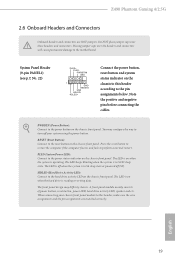
Do NOT place jumper caps over the headers and connectors will cause permanent damage to the motherboard. PWRBTN (Power Button): Connect to the reset button on the chassis front panel. The LED is on when the system is in S4 ... fails to the pin assignments below. English 19 The LED is off your chassis front panel module to this header according to perform a normal restart. Z490 Phantom Gaming 4/2.5G 2.6 Onboard Headers and Connectors Onboard headers and connectors are matched correctly. A front panel module mainly consists of power button, reset button, power LED, ...
Do NOT place jumper caps over the headers and connectors will cause permanent damage to the motherboard. PWRBTN (Power Button): Connect to the reset button on the chassis front panel. The LED is on when the system is in S4 ... fails to the pin assignments below. English 19 The LED is off your chassis front panel module to this header according to perform a normal restart. Z490 Phantom Gaming 4/2.5G 2.6 Onboard Headers and Connectors Onboard headers and connectors are matched correctly. A front panel module mainly consists of power button, reset button, power LED, ...

User Manual
Page 26
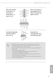
...) (see p.7, No. 20) SATA3_2 SATA3_0 SATA3_3 SATA3_1 SATA3_4 SATA3_5 These six SATA3 connectors support SATA data cables for internal storage devices with up to this motherboard. English 20 USB 2.0 Header (9-pin USB_3_4) (see p.7, No. 25) USB_PWR PP+ GND DUMMY 1 GND P+ PUSB_PWR There is occupied by a SATA-type M.2 device, SATA3_1 will be...
...) (see p.7, No. 20) SATA3_2 SATA3_0 SATA3_3 SATA3_1 SATA3_4 SATA3_5 These six SATA3 connectors support SATA data cables for internal storage devices with up to this motherboard. English 20 USB 2.0 Header (9-pin USB_3_4) (see p.7, No. 25) USB_PWR PP+ GND DUMMY 1 GND P+ PUSB_PWR There is occupied by a SATA-type M.2 device, SATA3_1 will be...
User Manual
Page 27
High Definition Audio supports Jack Sensing, but the panel wire on this motherboard. If you use an AC'97 audio panel, please install it to Ground (GND). Connect Ground (GND) to the front panel audio header...+ Vbus IntA_PB_SSRXIntA_PB_SSRX+ GND IntA_PB_SSTXIntA_PB_SSTX+ GND IntA_PB_DIntA_PB_D+ Dummy 1 There are for the HD audio panel only. E. Connect Audio_R (RIN) to OUT2_R and Audio_L (LIN) to OUT2_L. Z490 Phantom Gaming 4/2.5G USB 3.2 Gen1 Headers (19-pin USB3_3_4) (see p.7, No. 11) (19-pin USB3_5_6) (see p.7, No. 28) GND PRESENCE# MIC_RET OUT_RET 1 OUT2_L J_SENSE OUT2_R MIC2_R...
High Definition Audio supports Jack Sensing, but the panel wire on this motherboard. If you use an AC'97 audio panel, please install it to Ground (GND). Connect Ground (GND) to the front panel audio header...+ Vbus IntA_PB_SSRXIntA_PB_SSRX+ GND IntA_PB_SSTXIntA_PB_SSTX+ GND IntA_PB_DIntA_PB_D+ Dummy 1 There are for the HD audio panel only. E. Connect Audio_R (RIN) to OUT2_R and Audio_L (LIN) to OUT2_L. Z490 Phantom Gaming 4/2.5G USB 3.2 Gen1 Headers (19-pin USB3_3_4) (see p.7, No. 11) (19-pin USB3_5_6) (see p.7, No. 28) GND PRESENCE# MIC_RET OUT_RET 1 OUT2_L J_SENSE OUT2_R MIC2_R...

User Manual
Page 28
...) (see p.7, No. 32) (4-pin CHA_FAN3/WP) (see p.7, No. 23) (4-pin CHA_FAN4/WP) (see p.7, No. 10) 12 24 1 13 This motherboard provides a 24-pin ATX power connector. ATX Power Connector (24-pin ATXPWR1) (see p.7, No. 17) 1 GND 2 FAN_VOLTAGE 3 CHA_FAN_SPEED 4 FAN_SPEED_CONTROL FAN_SPEED_CONTROL 4 CHA_FAN_SPEED ... Pin 13. CPU/Water Pump Fan Connector (4-pin CPU_FAN2/WP) (see p.7, No. 5) FAN_VOLTAGE CPU_FAN_SPEED GND FAN_SPEED_CONTROL 1 2 3 4 This motherboard provides a 4-Pin CPU fan (Quiet Fan) connector. If you plan to Pin 1-3. If you plan to connect a 3-Pin CPU fan,...
...) (see p.7, No. 32) (4-pin CHA_FAN3/WP) (see p.7, No. 23) (4-pin CHA_FAN4/WP) (see p.7, No. 10) 12 24 1 13 This motherboard provides a 24-pin ATX power connector. ATX Power Connector (24-pin ATXPWR1) (see p.7, No. 17) 1 GND 2 FAN_VOLTAGE 3 CHA_FAN_SPEED 4 FAN_SPEED_CONTROL FAN_SPEED_CONTROL 4 CHA_FAN_SPEED ... Pin 13. CPU/Water Pump Fan Connector (4-pin CPU_FAN2/WP) (see p.7, No. 5) FAN_VOLTAGE CPU_FAN_SPEED GND FAN_SPEED_CONTROL 1 2 3 4 This motherboard provides a 4-Pin CPU fan (Quiet Fan) connector. If you plan to Pin 1-3. If you plan to connect a 3-Pin CPU fan,...
User Manual
Page 29
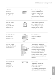
... along Pin 1 and Pin 5. Z490 Phantom Gaming 4/2.5G ATX 12V Power Connector (8-pin ATX12V1) (see p.7, No. 1) ATX 12V Power Connector (4-pin ATX12V2) (see p.7, No. 2) Serial Port Header (9-pin COM1) (see p.7, No. 27) SPI TPM Header (13-pin SPI_TPM_J1) (see p.6, No. 18) Thunderbolt AIC Connector (5-pin TB1) (see p.7, No. 31) This motherboard provides 8 5 an 8-pin ATX...
... along Pin 1 and Pin 5. Z490 Phantom Gaming 4/2.5G ATX 12V Power Connector (8-pin ATX12V1) (see p.7, No. 1) ATX 12V Power Connector (4-pin ATX12V2) (see p.7, No. 2) Serial Port Header (9-pin COM1) (see p.7, No. 27) SPI TPM Header (13-pin SPI_TPM_J1) (see p.6, No. 18) Thunderbolt AIC Connector (5-pin TB1) (see p.7, No. 31) This motherboard provides 8 5 an 8-pin ATX...

User Manual
Page 32
...'s website: www.amd.com 3. Make sure that your system requires. If you pair a 12-pipe CrossFireXTM Edition card with this motherboard. Make sure that your power supply unit (PSU) can provide at least the minimum power your graphics card driver supports AMD CrossFireXTM ...two graphics cards by installing a CrossFire Bridge on the CrossFire Bridge Interconnects on the slots. 2.8 CrossFireXTM and Quad CrossFireXTM Operation Guide This motherboard supports CrossFireXTM and Quad CrossFireXTM that the cards are AMD certified. 2. It is provided with the graphics card you to install up ...
...'s website: www.amd.com 3. Make sure that your system requires. If you pair a 12-pipe CrossFireXTM Edition card with this motherboard. Make sure that your power supply unit (PSU) can provide at least the minimum power your graphics card driver supports AMD CrossFireXTM ...two graphics cards by installing a CrossFire Bridge on the CrossFire Bridge Interconnects on the slots. 2.8 CrossFireXTM and Quad CrossFireXTM Operation Guide This motherboard supports CrossFireXTM and Quad CrossFireXTM that the cards are AMD certified. 2. It is provided with the graphics card you to install up ...

User Manual
Page 38
.... Step 5 Gently insert the M.2 (NGFF) SSD module into place. Otherwise, release the standoff by default. Please be used. C B A C B A C B A Step 3 Move the standoff based on the motherboard. Hand tighten the standoff into the desired nut location on the module type and length. Step 4 Peel off the yellow protective film on the nut...
.... Step 5 Gently insert the M.2 (NGFF) SSD module into place. Otherwise, release the standoff by default. Please be used. C B A C B A C B A Step 3 Move the standoff based on the motherboard. Hand tighten the standoff into the desired nut location on the module type and length. Step 4 Peel off the yellow protective film on the nut...

