

Intel Rapid Storage Guide
Page 12
... must be used to load the Intel® Rapid Storage Technology driver during POST, press Ctrl and i at the same time to enter the option ROM user interface. 2. Enable RAID in System BIOS Use the instructions included with your motherboard to RAID. 5. The F6 installation method is not required for Microsoft Windows 7 or Note Microsoft Windows 8. Click F2 or Delete to enter the BIOS Setup program after the Power-On-Self-Test (POST) memory test begins...
... must be used to load the Intel® Rapid Storage Technology driver during POST, press Ctrl and i at the same time to enter the option ROM user interface. 2. Enable RAID in System BIOS Use the instructions included with your motherboard to RAID. 5. The F6 installation method is not required for Microsoft Windows 7 or Note Microsoft Windows 8. Click F2 or Delete to enter the BIOS Setup program after the Power-On-Self-Test (POST) memory test begins...

Intel Rapid Storage Guide
Page 13
... temporarily continue loading drivers. At the prompt press Y to Specify Additional Device. 3. Use the up and down arrow keys to confirm your controller and continue. Press Enter to create a floppy disk with a screen asking you have successfully installed the driver and Windows setup should continue. Press Y to scroll through the list as all controllers may not be prompted Note with the Note necessary files. 4. Use the Floppy Configuration Utility to create...
... temporarily continue loading drivers. At the prompt press Y to Specify Additional Device. 3. Use the up and down arrow keys to confirm your controller and continue. Press Enter to create a floppy disk with a screen asking you have successfully installed the driver and Windows setup should continue. Press Y to scroll through the list as all controllers may not be prompted Note with the Note necessary files. 4. Use the Floppy Configuration Utility to create...

Intel Rapid Storage Guide
Page 16
... a RAID driver as part of the operating system. 16 You will then be used to load support for mass storage device(s). 2. Press S to install a third party SCSI or RAID driver. Note If you see a prompt that says, Please insert the disk labeled Manufacturer-supplied hardware support disk into Drive A:, insert a floppy disk containing the following steps to install the Intel® Rapid Storage Technology driver using F6 when in AHCI/RAID mode In order to install an...
... a RAID driver as part of the operating system. 16 You will then be used to load support for mass storage device(s). 2. Press S to install a third party SCSI or RAID driver. Note If you see a prompt that says, Please insert the disk labeled Manufacturer-supplied hardware support disk into Drive A:, insert a floppy disk containing the following steps to install the Intel® Rapid Storage Technology driver using F6 when in AHCI/RAID mode In order to install an...

RAID Installation Guide
Page 7
... p.8 -17 of this feature is not available for instructions on your USB flash drive into a USB port B. STEP 2: Use ASRock Easy RAID Installer Easy RAID Installer can copy the RAID driver from a support CD to set RAID configuration. Go to Advanced Storage Configuration and set the necessary RAID items in the BIOS before setting your system, and press key to complete the process. Please note that this document for all models A. Boot your RAID configuration. Follow the onscreen instruction to enter BIOS setup utility.
... p.8 -17 of this feature is not available for instructions on your USB flash drive into a USB port B. STEP 2: Use ASRock Easy RAID Installer Easy RAID Installer can copy the RAID driver from a support CD to set RAID configuration. Go to Advanced Storage Configuration and set the necessary RAID items in the BIOS before setting your system, and press key to complete the process. Please note that this document for all models A. Boot your RAID configuration. Follow the onscreen instruction to enter BIOS setup utility.

RAID Installation Guide
Page 23
... in RAID mode Windows® 10 does not support HDD's larger than 2TB. STEP 2: Install Windows® 10 64-bit OS Press to launch boot menu at system POST and choose the item "UEFI:" to use Windows® 10 64-bit. Please make sure to boot. 23 STEP 1: Copy Intel® RAID drivers into a USB flash disk You can download the drivers from ASRock's website and unzip the files into a USB flash disk or copy the files from ASRock's motherboard support CD...
... in RAID mode Windows® 10 does not support HDD's larger than 2TB. STEP 2: Install Windows® 10 64-bit OS Press to launch boot menu at system POST and choose the item "UEFI:" to use Windows® 10 64-bit. Please make sure to boot. 23 STEP 1: Copy Intel® RAID drivers into a USB flash disk You can download the drivers from ASRock's website and unzip the files into a USB flash disk or copy the files from ASRock's motherboard support CD...

User Manual
Page 4
... Memory Modules (DIMM) 15 2.4 Expansion Slots (PCI Express Slots) 17 2.5 Jumpers Setup 18 2.6 Onboard Headers and Connectors 19 2.7 Post Status Checker 25 2.8 CrossFireXTM and Quad CrossFireXTM Operation Guide 26 2.8.1 Installing Two CrossFireXTM-Ready Graphics Cards 26 2.8.2 Driver Installation and Setup 28 2.9 M.2 WiFi/BT Module and Intel® CNVi (Integrated WiFi/BT) Installation Guide 29 2.10 M.2_SSD (NGFF) Module Installation Guide (M2_2) 31 Chapter 3 Software and Utilities Operation 35 3.1 Installing Drivers 35 3.2 ASRock Motherboard Utility (Phantom Gaming...
... Memory Modules (DIMM) 15 2.4 Expansion Slots (PCI Express Slots) 17 2.5 Jumpers Setup 18 2.6 Onboard Headers and Connectors 19 2.7 Post Status Checker 25 2.8 CrossFireXTM and Quad CrossFireXTM Operation Guide 26 2.8.1 Installing Two CrossFireXTM-Ready Graphics Cards 26 2.8.2 Driver Installation and Setup 28 2.9 M.2 WiFi/BT Module and Intel® CNVi (Integrated WiFi/BT) Installation Guide 29 2.10 M.2_SSD (NGFF) Module Installation Guide (M2_2) 31 Chapter 3 Software and Utilities Operation 35 3.1 Installing Drivers 35 3.2 ASRock Motherboard Utility (Phantom Gaming...

User Manual
Page 7
...model you are using. Because the motherboard specifications and the BIOS software might be updated, the content of this documentation occur, the updated version will be available on ASRock's website as well. If you for M.2 Sockets (Optional) • 1 x I/O Panel Shield 1 English You may find the latest VGA cards and CPU support list on ASRock's website without notice. ASRock website http://www.asrock.com. 1.1 Package Contents • ASRock Z490 Phantom Gaming 4/2.5G Motherboard (ATX Form Factor) • ASRock Z490 Phantom Gaming 4/2.5G Quick Installation Guide • ASRock Z490...
...model you are using. Because the motherboard specifications and the BIOS software might be updated, the content of this documentation occur, the updated version will be available on ASRock's website as well. If you for M.2 Sockets (Optional) • 1 x I/O Panel Shield 1 English You may find the latest VGA cards and CPU support list on ASRock's website without notice. ASRock website http://www.asrock.com. 1.1 Package Contents • ASRock Z490 Phantom Gaming 4/2.5G Motherboard (ATX Form Factor) • ASRock Z490 Phantom Gaming 4/2.5G Quick Installation Guide • ASRock Z490...

User Manual
Page 11
...1 x 24 pin ATX Power Connector • 1 x 8 pin 12V Power Connector • 1 x 4 pin 12V Power Connector • 1 x Front Panel Audio Connector • 1 x Thunderbolt AIC Connector (5-pin) (Supports ASRock Thunderbolt 3 AIC R2.0 Card only) • 1 x USB 2.0 Header (Supports 2 USB 2.0 ports) (Supports ESD Protection) • 2 x USB 3.2 Gen1 Headers (Support 4 USB 3.2 Gen1 ports) (Supports ESD Protection) BIOS Feature • AMI UEFI Legal BIOS with multilingual GUI support • ACPI 6.0 Compliant wake up events • SMBIOS 2.7 Support • CPU Core/Cache, GT, DRAM, PCH, VCCIO...
...1 x 24 pin ATX Power Connector • 1 x 8 pin 12V Power Connector • 1 x 4 pin 12V Power Connector • 1 x Front Panel Audio Connector • 1 x Thunderbolt AIC Connector (5-pin) (Supports ASRock Thunderbolt 3 AIC R2.0 Card only) • 1 x USB 2.0 Header (Supports 2 USB 2.0 ports) (Supports ESD Protection) • 2 x USB 3.2 Gen1 Headers (Support 4 USB 3.2 Gen1 ports) (Supports ESD Protection) BIOS Feature • AMI UEFI Legal BIOS with multilingual GUI support • ACPI 6.0 Compliant wake up events • SMBIOS 2.7 Support • CPU Core/Cache, GT, DRAM, PCH, VCCIO...

User Manual
Page 14
... Pump Fan Connector (CHA_FAN4/WP) 18 SPI TPM Header (SPI_TPM_J1) 19 Power LED and Speaker Header (SPK_PLED1) 20 SATA3 Connector (SATA3_5) 21 SATA3 Connector (SATA3_4) 22 System Panel Header (PANEL1) 23 Chassis/Water Pump Fan Connector (CHA_FAN3/WP) 24 USB 3.2 Gen1 Header (USB3_5_6) 25 USB 2.0 Header (USB_3_4) 26 Addressable LED Header (ADDR_LED1) 27 COM Port Header (COM1) 28 Front Panel Audio Header (HD_AUDIO1) 29 RGB LED Header (RGB_LED1) 30 Clear CMOS Jumper (CLRMOS1) 31 Thunderbolt AIC Connector (TB1) 32 Chassis/Water Pump Fan Connector...
... Pump Fan Connector (CHA_FAN4/WP) 18 SPI TPM Header (SPI_TPM_J1) 19 Power LED and Speaker Header (SPK_PLED1) 20 SATA3 Connector (SATA3_5) 21 SATA3 Connector (SATA3_4) 22 System Panel Header (PANEL1) 23 Chassis/Water Pump Fan Connector (CHA_FAN3/WP) 24 USB 3.2 Gen1 Header (USB3_5_6) 25 USB 2.0 Header (USB_3_4) 26 Addressable LED Header (ADDR_LED1) 27 COM Port Header (COM1) 28 Front Panel Audio Header (HD_AUDIO1) 29 RGB LED Header (RGB_LED1) 30 Clear CMOS Jumper (CLRMOS1) 31 Thunderbolt AIC Connector (TB1) 32 Chassis/Water Pump Fan Connector...

User Manual
Page 23
PCIe slots: PCIE1 (PCIe 3.0 x1 slot) is used for PCI Express x4 lane width graphics cards. Z490 Phantom Gaming 4/2.5G 2.4 Expansion Slots (PCI Express Slots) There are 5 PCI Express slots on the motherboard. Please read the documentation of the expansion card and make sure that the power supply is switched off or the power cord is used for the card before you start the installation. PCIE2 (PCIe 3.0 x16 slot) is used for PCI Express x1 lane width cards. PCIE4 (PCIe 3.0 x16 slot) is used for PCI Express x16 lane width graphics cards. English 17...
PCIe slots: PCIE1 (PCIe 3.0 x1 slot) is used for PCI Express x4 lane width graphics cards. Z490 Phantom Gaming 4/2.5G 2.4 Expansion Slots (PCI Express Slots) There are 5 PCI Express slots on the motherboard. Please read the documentation of the expansion card and make sure that the power supply is switched off or the power cord is used for the card before you start the installation. PCIE2 (PCIe 3.0 x16 slot) is used for PCI Express x1 lane width cards. PCIE4 (PCIe 3.0 x16 slot) is used for PCI Express x16 lane width graphics cards. English 17...
User Manual
Page 25
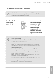
... Drive Activity LED): Connect to the pin assignments below. Z490 Phantom Gaming 4/2.5G 2.6 Onboard Headers and Connectors Onboard headers and connectors are matched correctly. A front panel module mainly consists of power button, reset button, power LED, hard drive activity LED, speaker and etc. When connecting your system using the power button. The LED is operating. PWRBTN (Power Button): Connect to the power button on the chassis to the motherboard. Do NOT place jumper caps over the headers and connectors will cause permanent damage to this header, make sure the wire...
... Drive Activity LED): Connect to the pin assignments below. Z490 Phantom Gaming 4/2.5G 2.6 Onboard Headers and Connectors Onboard headers and connectors are matched correctly. A front panel module mainly consists of power button, reset button, power LED, hard drive activity LED, speaker and etc. When connecting your system using the power button. The LED is operating. PWRBTN (Power Button): Connect to the power button on the chassis to the motherboard. Do NOT place jumper caps over the headers and connectors will cause permanent damage to this header, make sure the wire...
User Manual
Page 29
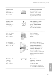
To use a 4-pin 4 1 ATX power supply, please plug it along Pin 1 and Pin 5. RRXD1 DDTR#1 DDSR#1 CCTS#1 1 RRI#1 RRTS#1 GND TTXD1 DDCD#1 This COM1 header supports a serial port module. English 23 Please connect an ATX 12V power supply to this connector. *The power supply plug fits into this connector in card (AIC) to this connector via the GPIO cable. *Please install the Thunderbolt™ AIC card to PCIE4 (default slot). A TPM system also helps enhance network security, protects digital identities...
To use a 4-pin 4 1 ATX power supply, please plug it along Pin 1 and Pin 5. RRXD1 DDTR#1 DDSR#1 CCTS#1 1 RRI#1 RRTS#1 GND TTXD1 DDCD#1 This COM1 header supports a serial port module. English 23 Please connect an ATX 12V power supply to this connector. *The power supply plug fits into this connector in card (AIC) to this connector via the GPIO cable. *Please install the Thunderbolt™ AIC card to PCIE4 (default slot). A TPM system also helps enhance network security, protects digital identities...

User Manual
Page 32
... PCI Express x16 graphics cards. 1. Make sure that your power supply unit (PSU) can provide at least the minimum power your graphics card driver supports AMD CrossFireXTM technology. Make sure that the cards are AMD certified. 2. Please refer to enable CrossFireXTM. Download the drivers from the AMD's website: www.amd.com 3. Make sure that your system requires. If you pair a 12-pipe CrossFireXTM Edition card with the graphics card you to install up to AMD graphics card manuals...
... PCI Express x16 graphics cards. 1. Make sure that your power supply unit (PSU) can provide at least the minimum power your graphics card driver supports AMD CrossFireXTM technology. Make sure that the cards are AMD certified. 2. Please refer to enable CrossFireXTM. Download the drivers from the AMD's website: www.amd.com 3. Make sure that your system requires. If you pair a 12-pipe CrossFireXTM Edition card with the graphics card you to install up to AMD graphics card manuals...

User Manual
Page 34
... optional download. Select the GPU number according to installation. Step 5 In the left pane, click Performance and then AMD CrossFireXTM. English 28 Then select Enable AMD CrossFireX and click Apply. AMD Catalyst Control Center Step 4 Double-click the AMD Catalyst Control Center icon in your graphics card and click Apply. We recommend using this utility to uninstall any VGA drivers installed in the Windows® system tray. Step 2 Remove...
... optional download. Select the GPU number according to installation. Step 5 In the left pane, click Performance and then AMD CrossFireXTM. English 28 Then select Enable AMD CrossFireX and click Apply. AMD Catalyst Control Center Step 4 Double-click the AMD Catalyst Control Center icon in your graphics card and click Apply. We recommend using this utility to uninstall any VGA drivers installed in the Windows® system tray. Step 2 Remove...
User Manual
Page 41
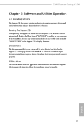
... install those required drivers. The CD automatically displays the Main Menu if "AUTORUN" is enabled in the Support CD to your CD-ROM drive. Running The Support CD To begin using the support CD, insert the CD into your system will be auto-detected and listed on a specific item then follow the order from top to bottom to install it. 35 English Z490 Phantom Gaming 4/2.5G Chapter 3 Software and Utilities Operation 3.1 Installing Drivers The Support...
... install those required drivers. The CD automatically displays the Main Menu if "AUTORUN" is enabled in the Support CD to your CD-ROM drive. Running The Support CD To begin using the support CD, insert the CD into your system will be auto-detected and listed on a specific item then follow the order from top to bottom to install it. 35 English Z490 Phantom Gaming 4/2.5G Chapter 3 Software and Utilities Operation 3.1 Installing Drivers The Support...

User Manual
Page 76
... (only if the system supports 64 bit PCI decoding). Auto mode is optimizing for PCIE1. 70 English VT-d Intel® Virtualization Technology for Directed I/O helps your virtual machine monitor better utilize hardware by improving application compatibility and reliability, and providing additional levels of manageability, security, isolation, and I/O performance. SR-IOV Support If system has SR-IOV capable PCIe Devices, this option Enables or Disables Single Root IO Virtualization Support.
... (only if the system supports 64 bit PCI decoding). Auto mode is optimizing for PCIE1. 70 English VT-d Intel® Virtualization Technology for Directed I/O helps your virtual machine monitor better utilize hardware by improving application compatibility and reliability, and providing additional levels of manageability, security, isolation, and I/O performance. SR-IOV Support If system has SR-IOV capable PCIe Devices, this option Enables or Disables Single Root IO Virtualization Support.

User Manual
Page 77
.... Onboard HD Audio Enable/disable onboard HD audio. PCI Express Native Control Select Enable for PCIE3. DMI ASPM Support This option enables/disables the control of ASPM on CPU side of memory that is allocated to disable the integrated graphics when an external graphics card is installed. PCIE ASPM Support This option enables/disables the ASPM support for all PCH PCIE devices. Select enable to enable onboard HD audio and 71 English IGPU Multi-Monitor Select disable to the integrated graphics processor when the system boots up. Z490 Phantom Gaming 4/2.5G PCIE2 Link Speed...
.... Onboard HD Audio Enable/disable onboard HD audio. PCI Express Native Control Select Enable for PCIE3. DMI ASPM Support This option enables/disables the control of ASPM on CPU side of memory that is allocated to disable the integrated graphics when an external graphics card is installed. PCIE ASPM Support This option enables/disables the ASPM support for all PCH PCIE devices. Select enable to enable onboard HD audio and 71 English IGPU Multi-Monitor Select disable to the integrated graphics processor when the system boots up. Z490 Phantom Gaming 4/2.5G PCIE2 Link Speed...

User Manual
Page 80
... allows you to allow booting from Usb devices which are present behind Thunderbolt. SW SMI on TBT Hot-plug When enbled, BIOS generates ACPI Notify. 74 English Titan Ridge Workaround for OSUP Enable or disable Titan Ridge Workaround for the Thunderbolt ports. 4.6.4 Intel(R) Thunderbolt Discrete Thunderbolt(TM) Support Enable or disable the Discrete Thunderbolt(TM) Support. Thunderbolt Boot Support Enabled to TBT devices. Thunderbolt Usb Support Enabled to choose a security...
... allows you to allow booting from Usb devices which are present behind Thunderbolt. SW SMI on TBT Hot-plug When enbled, BIOS generates ACPI Notify. 74 English Titan Ridge Workaround for OSUP Enable or disable Titan Ridge Workaround for the Thunderbolt ports. 4.6.4 Intel(R) Thunderbolt Discrete Thunderbolt(TM) Support Enable or disable the Discrete Thunderbolt(TM) Support. Thunderbolt Boot Support Enabled to TBT devices. Thunderbolt Usb Support Enabled to choose a security...

User Manual
Page 87
... Setting Enable or disable sound effects in your USB pen drive before using this to configure internet connection settings for you. Please setup network configuration before using Internet Flash. *For BIOS backup and recovery purpose, it is recommended to download the UEFI firmware. 81 English UEFI Download Server Select a server to plug in the setup utility. Network Configuration Use this function. DHCP (Auto IP), Auto ASRock Internet Flash downloads and updates the latest UEFI firmware version from our servers for Internet Flash. Z490 Phantom Gaming 4/2.5G Internet Flash...
... Setting Enable or disable sound effects in your USB pen drive before using this to configure internet connection settings for you. Please setup network configuration before using Internet Flash. *For BIOS backup and recovery purpose, it is recommended to download the UEFI firmware. 81 English UEFI Download Server Select a server to plug in the setup utility. Network Configuration Use this function. DHCP (Auto IP), Auto ASRock Internet Flash downloads and updates the latest UEFI firmware version from our servers for Internet Flash. Z490 Phantom Gaming 4/2.5G Internet Flash...

User Manual
Page 92
... enable or disable support for the system. User Password Set or change the password for the administrator account. Supervisor Password Set or change the supervisor/user password for Secure Boot. Secure Boot Use this item to remove the password. Disable this option to remove the password. Leave it blank and press enter to use discrete TPM Module. 86 English Intel(R) Platform Trust Technology Enable/disable Intel PTT in the UEFI Setup Utility. You may set or change the password for the user account. 4.9 Security Screen...
... enable or disable support for the system. User Password Set or change the password for the administrator account. Supervisor Password Set or change the supervisor/user password for Secure Boot. Secure Boot Use this item to remove the password. Disable this option to remove the password. Leave it blank and press enter to use discrete TPM Module. 86 English Intel(R) Platform Trust Technology Enable/disable Intel PTT in the UEFI Setup Utility. You may set or change the password for the user account. 4.9 Security Screen...


