
User Manual
Page 4
...the CPU 12 2.2 Installing the CPU Fan and Heatsink 15 2.3 Installing Memory Modules (DIMM) 16 2.4 Expansion Slots (PCI and PCI Express Slots) 18 2.5 Jumpers Setup 19 2.6 Onboard Headers and Connectors 20 2.7 CrossFireXTM and Quad CrossFireXTM Operation Guide 25 2.7.1 Installing Two CrossFireXTM-Ready Graphics Cards 25 2.7.2 Driver Installation and Setup 27 2.8 M.2_SSD (NGFF) Module Installation Guide 28 Chapter 3 Software and Utilities Operation 32 3.1 Installing Drivers 32 3.2 A-Tuning 33 3.2.1 Installing A-Tuning 33 3.2.2 Using A-Tuning 33 3.3 ASRock Live Update...
...the CPU 12 2.2 Installing the CPU Fan and Heatsink 15 2.3 Installing Memory Modules (DIMM) 16 2.4 Expansion Slots (PCI and PCI Express Slots) 18 2.5 Jumpers Setup 19 2.6 Onboard Headers and Connectors 20 2.7 CrossFireXTM and Quad CrossFireXTM Operation Guide 25 2.7.1 Installing Two CrossFireXTM-Ready Graphics Cards 25 2.7.2 Driver Installation and Setup 27 2.8 M.2_SSD (NGFF) Module Installation Guide 28 Chapter 3 Software and Utilities Operation 32 3.1 Installing Drivers 32 3.2 A-Tuning 33 3.2.1 Installing A-Tuning 33 3.2.2 Using A-Tuning 33 3.3 ASRock Live Update...
User Manual
Page 7
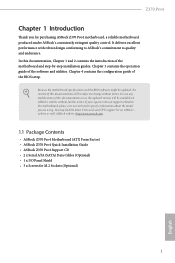
... Package Contents • ASRock Z370 Pro4 Motherboard (ATX Form Factor) • ASRock Z370 Pro4 Quick Installation Guide • ASRock Z370 Pro4 Support CD • 2 x Serial ATA (SATA) Data Cables (Optional) • 1 x I/O Panel Shield • 3 x Screws for purchasing ASRock Z370 Pro4 motherboard, a reliable motherboard produced under ASRock's consistently stringent quality control. In case any modifications of the BIOS setup. Z370 Pro4 Chapter 1 Introduction Thank you for M.2 Sockets (Optional) 1 English Chapter 4 contains the configuration guide of this documentation, Chapter...
... Package Contents • ASRock Z370 Pro4 Motherboard (ATX Form Factor) • ASRock Z370 Pro4 Quick Installation Guide • ASRock Z370 Pro4 Support CD • 2 x Serial ATA (SATA) Data Cables (Optional) • 1 x I/O Panel Shield • 3 x Screws for purchasing ASRock Z370 Pro4 motherboard, a reliable motherboard produced under ASRock's consistently stringent quality control. In case any modifications of the BIOS setup. Z370 Pro4 Chapter 1 Introduction Thank you for M.2 Sockets (Optional) 1 English Chapter 4 contains the configuration guide of this documentation, Chapter...

User Manual
Page 9
... Color (12bpc), xvYCC and HBR (High Bit Rate Audio) with HDMI Port (Compliant HDMI monitor is required to use an HD front panel audio module and enable the multi-channel audio feature through the audio driver. • Premium Blu-ray Audio support • Supports Surge Protection • ELNA Audio Caps English 3 Z370 Pro4 Graphics Audio * Intel® UHD Graphics Built-in Visuals and the VGA outputs can be supported only with processors which are GPU integrated. •...
... Color (12bpc), xvYCC and HBR (High Bit Rate Audio) with HDMI Port (Compliant HDMI monitor is required to use an HD front panel audio module and enable the multi-channel audio feature through the audio driver. • Premium Blu-ray Audio support • Supports Surge Protection • ELNA Audio Caps English 3 Z370 Pro4 Graphics Audio * Intel® UHD Graphics Built-in Visuals and the VGA outputs can be supported only with processors which are GPU integrated. •...

User Manual
Page 10
... occupied by a SATA-type M.2 device, SATA_5 will be disabled. * If M2_2 is occupied by a SATA-type M.2 device, SATA_0 will be disabled. • 2 x Ultra M.2 Sockets (M2_1 and M2_2), supports M Key type 2230/2242/2260/2280 M.2 SATA3 6.0 Gb/s module and M.2 PCI Express module up to Gen3 x4 (32 Gb/s)** ** Supports Intel® OptaneTM Technology ** Supports NVMe SSD as boot disks ** Supports ASRock U.2 Kit Connector • 1 x COM Port Header • 1 x TPM Header • 1 x Chassis Intrusion Header • 1 x Power LED and Speaker Header • 1 x CPU Fan Connector (4-pin) English 4
... occupied by a SATA-type M.2 device, SATA_5 will be disabled. * If M2_2 is occupied by a SATA-type M.2 device, SATA_0 will be disabled. • 2 x Ultra M.2 Sockets (M2_1 and M2_2), supports M Key type 2230/2242/2260/2280 M.2 SATA3 6.0 Gb/s module and M.2 PCI Express module up to Gen3 x4 (32 Gb/s)** ** Supports Intel® OptaneTM Technology ** Supports NVMe SSD as boot disks ** Supports ASRock U.2 Kit Connector • 1 x COM Port Header • 1 x TPM Header • 1 x Chassis Intrusion Header • 1 x Power LED and Speaker Header • 1 x CPU Fan Connector (4-pin) English 4
User Manual
Page 11
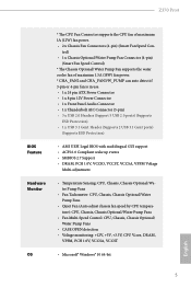
...or 4-pin fan is in use. • 1 x 24 pin ATX Power Connector • 1 x 8 pin 12V Power Connector • 1 x Front Panel Audio Connector • 1 x Thunderbolt AIC Connector (5-pin) • 3 x USB 2.0 Headers (Support 5 USB 2.0 ports) (Supports ESD Protection) • 1 x USB 3.1 Gen1 Header (Supports 2 USB 3.1 Gen1 ports) (Supports ESD Protection) • AMI UEFI Legal BIOS with multilingual GUI support • ACPI 6.0 Compliant wake up events • SMBIOS 2.7 Support • DRAM, PCH 1.0V, VCCIO, VCCST, VCCSA, VPPM Voltage Multi-adjustment • Temperature Sensing: CPU, Chassis...
...or 4-pin fan is in use. • 1 x 24 pin ATX Power Connector • 1 x 8 pin 12V Power Connector • 1 x Front Panel Audio Connector • 1 x Thunderbolt AIC Connector (5-pin) • 3 x USB 2.0 Headers (Support 5 USB 2.0 ports) (Supports ESD Protection) • 1 x USB 3.1 Gen1 Header (Supports 2 USB 3.1 Gen1 ports) (Supports ESD Protection) • AMI UEFI Legal BIOS with multilingual GUI support • ACPI 6.0 Compliant wake up events • SMBIOS 2.7 Support • DRAM, PCH 1.0V, VCCIO, VCCST, VCCSA, VPPM Voltage Multi-adjustment • Temperature Sensing: CPU, Chassis...

User Manual
Page 14
... 288-pin DDR4 DIMM Slots (DDR4_A2, DDR4_B2) 5 CPU Fan Connector (CPU_FAN1) 6 ATX Power Connector (ATXPWR1) 7 USB 3.1 Gen1 Header (USB3_5_6) 8 SATA3 Connector (SATA_5) 9 SATA3 Connector (SATA_4) 10 SATA3 Connector (SATA_3) 11 SATA3 Connector (SATA_2) 12 SATA3 Connector (SATA_1) 13 SATA3 Connector (SATA_0) 14 System Panel Header (PANEL1) 15 Power LED and Speaker Header (SPK_PLED1) 16 Chassis Fan / Waterpump Fan Connector (CHA_FAN3/W_PUMP) 17 Chassis Fan Connector (CHA_FAN1) 18 USB 2.0 Header (USB_1_2) 19 USB 2.0 Header (USB_3_4) 20 USB 2.0 Header (USB_5) 21 Clear CMOS Jumper (CLRMOS1) 22 Chassis...
... 288-pin DDR4 DIMM Slots (DDR4_A2, DDR4_B2) 5 CPU Fan Connector (CPU_FAN1) 6 ATX Power Connector (ATXPWR1) 7 USB 3.1 Gen1 Header (USB3_5_6) 8 SATA3 Connector (SATA_5) 9 SATA3 Connector (SATA_4) 10 SATA3 Connector (SATA_3) 11 SATA3 Connector (SATA_2) 12 SATA3 Connector (SATA_1) 13 SATA3 Connector (SATA_0) 14 System Panel Header (PANEL1) 15 Power LED and Speaker Header (SPK_PLED1) 16 Chassis Fan / Waterpump Fan Connector (CHA_FAN3/W_PUMP) 17 Chassis Fan Connector (CHA_FAN1) 18 USB 2.0 Header (USB_1_2) 19 USB 2.0 Header (USB_3_4) 20 USB 2.0 Header (USB_5) 21 Clear CMOS Jumper (CLRMOS1) 22 Chassis...

User Manual
Page 24
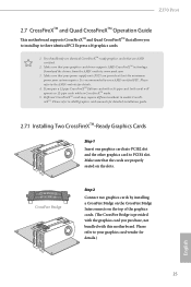
... chassis fan connector (CHA_FAN1, CHA_FAN2 or CHA_FAN3) when using multiple graphics cards. PCIE4 (PCIe 3.0 x16 slot) is occupied, PCIE4 slot will run at x2 mode. PCIE5 (PCIe 3.0 x1 slot) is used for PCI Express x4 lane width graphics cards. PCIe slots: PCIE1 (PCIe 3.0 x1 slot) is used for the card before you start the installation. PCIe Slot Configurations Single Graphics Card PCIE2 x16 PCIE4 N/A Two Graphics Cards in CrossFireXTM Mode x16 x4 For a better thermal environment, please connect a chassis fan to install expansion cards that the power supply is switched...
... chassis fan connector (CHA_FAN1, CHA_FAN2 or CHA_FAN3) when using multiple graphics cards. PCIE4 (PCIe 3.0 x16 slot) is occupied, PCIE4 slot will run at x2 mode. PCIE5 (PCIe 3.0 x1 slot) is used for PCI Express x4 lane width graphics cards. PCIe slots: PCIE1 (PCIe 3.0 x1 slot) is used for the card before you start the installation. PCIe Slot Configurations Single Graphics Card PCIE2 x16 PCIE4 N/A Two Graphics Cards in CrossFireXTM Mode x16 x4 For a better thermal environment, please connect a chassis fan to install expansion cards that the power supply is switched...

User Manual
Page 27
... There are two USB 2.0 headers on this motherboard. English 21 Each USB 2.0 header can support one USB 2.0 header on this header. Z370 Pro4 Power LED and Speaker Header (7-pin SPK_PLED1) (see p.7, No. 20) SATA_0 SATA_2 SATA_4 SATA_1 SATA_3 SATA_5 These six SATA3 connectors support SATA data cables for internal storage devices with up to this motherboard. Each header can support two ports. 1 GND P+ PUSB_PWR There is occupied by a SATA-type M.2 device, SATA_0 will be disabled. Please connect the chassis power LED and the chassis speaker to 6.0 Gb...
... There are two USB 2.0 headers on this motherboard. English 21 Each USB 2.0 header can support one USB 2.0 header on this header. Z370 Pro4 Power LED and Speaker Header (7-pin SPK_PLED1) (see p.7, No. 20) SATA_0 SATA_2 SATA_4 SATA_1 SATA_3 SATA_5 These six SATA3 connectors support SATA data cables for internal storage devices with up to this motherboard. Each header can support two ports. 1 GND P+ PUSB_PWR There is occupied by a SATA-type M.2 device, SATA_0 will be disabled. Please connect the chassis power LED and the chassis speaker to 6.0 Gb...
User Manual
Page 31
Download the drivers from the AMD's website: www.amd.com 3. It is provided with the graphics card you purchase, not bundled with a 16-pipe card, both cards will operate as 12-pipe cards while in CrossFireXTM mode. 5. CrossFire Bridge Step 2 Connect two graphics cards by installing a CrossFire Bridge on the CrossFire Bridge Interconnects on the slots. Z370 Pro4 2.7 CrossFireXTM and Quad CrossFireXTM Operation Guide This motherboard supports CrossFireXTM and Quad CrossFireXTM...
Download the drivers from the AMD's website: www.amd.com 3. It is provided with the graphics card you purchase, not bundled with a 16-pipe card, both cards will operate as 12-pipe cards while in CrossFireXTM mode. 5. CrossFire Bridge Step 2 Connect two graphics cards by installing a CrossFire Bridge on the CrossFire Bridge Interconnects on the slots. Z370 Pro4 2.7 CrossFireXTM and Quad CrossFireXTM Operation Guide This motherboard supports CrossFireXTM and Quad CrossFireXTM...
User Manual
Page 33
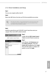
... and boot into OS. The Catalyst Uninstaller is an optional download. We recommend using this utility to uninstall any VGA drivers installed in the Windows® system tray. Select the GPU number according to installation. Step 3 Install the required drivers and CATALYST Control Center then restart your graphics card and click Apply. Z370 Pro4 2.7.2 Driver Installation and Setup Step 1 Power on your system. Step 2 Remove the AMD drivers if you have any previously installed Catalyst drivers...
... and boot into OS. The Catalyst Uninstaller is an optional download. We recommend using this utility to uninstall any VGA drivers installed in the Windows® system tray. Select the GPU number according to installation. Step 3 Install the required drivers and CATALYST Control Center then restart your graphics card and click Apply. Z370 Pro4 2.7.2 Driver Installation and Setup Step 1 Power on your system. Step 2 Remove the AMD drivers if you have any previously installed Catalyst drivers...
User Manual
Page 38
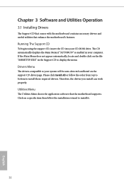
..., locate and double click on the support CD driver page. Click on a specific item then follow the order from top to bottom to your system will be auto-detected and listed on the file "ASRSETUP.EXE" in your CD-ROM drive. Please click Install All or follow the installation wizard to display the menu. Therefore, the drivers you install can work properly. Chapter 3 Software and Utilities Operation 3.1 Installing Drivers The Support...
..., locate and double click on the support CD driver page. Click on a specific item then follow the order from top to bottom to your system will be auto-detected and listed on the file "ASRSETUP.EXE" in your CD-ROM drive. Please click Install All or follow the installation wizard to display the menu. Therefore, the drivers you install can work properly. Chapter 3 Software and Utilities Operation 3.1 Installing Drivers The Support...

User Manual
Page 54
... SSE workloads. BCLK Frequency The CPU speed is suggested for BCLK overclocking. Boot Performance Mode Default is ideal for better power saving and heat dissipation. Reliability Stress Restrictor Disable or Enable Reliability Stress Restrictor feature. This is Max Non-Turbo performance mode. Intel Turbo Boost Technology Intel Turbo Boost Technology enables the processor to avoid high voltage overrides. FCLK Frequency Configure the FCLK Frequency. Disable to switch between multiple frequencies and voltage points for BCLK...
... SSE workloads. BCLK Frequency The CPU speed is suggested for BCLK overclocking. Boot Performance Mode Default is ideal for better power saving and heat dissipation. Reliability Stress Restrictor Disable or Enable Reliability Stress Restrictor feature. This is Max Non-Turbo performance mode. Intel Turbo Boost Technology Intel Turbo Boost Technology enables the processor to avoid high voltage overrides. FCLK Frequency Configure the FCLK Frequency. Disable to switch between multiple frequencies and voltage points for BCLK...

User Manual
Page 66
Top of Lower Usable Dram Set the maximum value of the installed graphic controller. Above 4G Decoding Enable or disable 64bit capable Devices to adjust automatically based on the largest MMIO length of TOLUD. 4.6.2 Chipset Configuration Primary Graphics Adapter Select a primary VGA. PCIE1 Link Speed Select the link speed for Directed I/O helps your virtual machine monitor better utilize hardware by improving application compatibility and reliability, and providing additional levels...
Top of Lower Usable Dram Set the maximum value of the installed graphic controller. Above 4G Decoding Enable or disable 64bit capable Devices to adjust automatically based on the largest MMIO length of TOLUD. 4.6.2 Chipset Configuration Primary Graphics Adapter Select a primary VGA. PCIE1 Link Speed Select the link speed for Directed I/O helps your virtual machine monitor better utilize hardware by improving application compatibility and reliability, and providing additional levels...

User Manual
Page 67
... devices failure. Disabling those interrupts may be used by PCH devices. PCI Express Native Control Select Enable for PCIE4. PCH PCIE ASPM Support This option enables/disables the ASPM support for PCIE5. Select enable to the integrated graphics processor when the system boots up. PCIE5 Link Speed Select the link speed for all PCH PCIE devices. PCH DMI ASPM Support This option enables/disables the ASPM support for PCIE3. IGPU Multi-Monitor Select disable to disable the integrated graphics when an external graphics card...
... devices failure. Disabling those interrupts may be used by PCH devices. PCI Express Native Control Select Enable for PCIE4. PCH PCIE ASPM Support This option enables/disables the ASPM support for PCIE5. Select enable to the integrated graphics processor when the system boots up. PCIE5 Link Speed Select the link speed for all PCH PCIE devices. PCH DMI ASPM Support This option enables/disables the ASPM support for PCIE3. IGPU Multi-Monitor Select disable to disable the integrated graphics when an external graphics card...

User Manual
Page 72
4.6.5 Super IO Configuration Serial Port Enable or disable the Serial port. PS2 Y-Cable Enable the PS2 Y-Cable or set this option to Auto. 66 English Serial Port Address Select the address of the Serial port.
4.6.5 Super IO Configuration Serial Port Enable or disable the Serial port. PS2 Y-Cable Enable the PS2 Y-Cable or set this option to Auto. 66 English Serial Port Address Select the address of the Serial port.

User Manual
Page 73
... waked up by a PCIE/PCI device and enable wake on LAN. ACPI HEPT Table Enable the High Precision Event Timer for better performance. PCIE/PCI Devices Power On Allow the system to be waked up by the real time clock alarm. USB Keyboard/Remote Power On Allow the system to be waked up by a PS/2 Keyboard. RTC Alarm Power On Allow the system to be waked up by onboard COM port modem Ring-In signals. Set...
... waked up by a PCIE/PCI device and enable wake on LAN. ACPI HEPT Table Enable the High Precision Event Timer for better performance. PCIE/PCI Devices Power On Allow the system to be waked up by the real time clock alarm. USB Keyboard/Remote Power On Allow the system to be waked up by a PS/2 Keyboard. RTC Alarm Power On Allow the system to be waked up by onboard COM port modem Ring-In signals. Set...
User Manual
Page 77
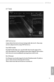
... RAID driver from the support CD to RAID, then you are having trouble with your USB storage device. Boot Manager Boot Manager is specifically designed for the dual OS platform/multi-OS platform users to easily customize and manage the boot menu. *Please connect more than one boot devices to use this tool. 71 English 4.7 Tools Z370 Pro4 UEFI Tech Service Contact ASRock Tech Service if you can start installing the operating system in RAID mode. Please setup network configuration before using UEFI Tech Service...
... RAID driver from the support CD to RAID, then you are having trouble with your USB storage device. Boot Manager Boot Manager is specifically designed for the dual OS platform/multi-OS platform users to easily customize and manage the boot menu. *Please connect more than one boot devices to use this tool. 71 English 4.7 Tools Z370 Pro4 UEFI Tech Service Contact ASRock Tech Service if you can start installing the operating system in RAID mode. Please setup network configuration before using UEFI Tech Service...
User Manual
Page 78
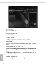
... Flash - DHCP (Auto IP), Auto ASRock Internet Flash downloads and updates the latest UEFI firmware version from our servers for the Boot Manager. Boot Manager Timeout Enable/disable the Boot Manager Timeout. Network Configuration Use this function. Timeout Seconds Configure the number of seconds to configure internet connection settings for Internet Flash. 72 English Boot Manager Enable/disable the Boot Manager. Please setup network configuration before using this to wait for you. Instant Flash Save UEFI files in your USB storage device and run Instant Flash to plug...
... Flash - DHCP (Auto IP), Auto ASRock Internet Flash downloads and updates the latest UEFI firmware version from our servers for the Boot Manager. Boot Manager Timeout Enable/disable the Boot Manager Timeout. Network Configuration Use this function. Timeout Seconds Configure the number of seconds to configure internet connection settings for Internet Flash. 72 English Boot Manager Enable/disable the Boot Manager. Please setup network configuration before using this to wait for you. Instant Flash Save UEFI files in your USB storage device and run Instant Flash to plug...

User Manual
Page 83
... password. Intel(R) Platform Trust Technology Enable/disable Intel PTT in the UEFI Setup Utility. Leave it blank and press enter to remove the password. Disable this option to change the settings in the UEFI Setup Utility. Secure Boot Use this item to change the password for the user account. Users are unable to enable or disable support for the system. Z370 Pro4 4.9 Security Screen In this section you may also clear the user password. Supervisor Password Set or change the settings in ME. User Password Set or change the supervisor/user password...
... password. Intel(R) Platform Trust Technology Enable/disable Intel PTT in the UEFI Setup Utility. Leave it blank and press enter to remove the password. Disable this option to change the settings in the UEFI Setup Utility. Secure Boot Use this item to change the password for the user account. Users are unable to enable or disable support for the system. Z370 Pro4 4.9 Security Screen In this section you may also clear the user password. Supervisor Password Set or change the settings in ME. User Password Set or change the supervisor/user password...

User Manual
Page 84
... way to enter this item to be waked up by the onboard LAN. 78 English Boot Option Priorities Boot Option #1 Set the system boot order. In fast mode you are using an external graphics card. Boot From Onboard LAN Allow the system to set the system boot order from an USB storage device. Boot Option #2 Set the system boot order. The VBIOS must support UEFI GOP if you may not boot from USB devices. 4.10 Boot Screen This section displays the available devices on your...
... way to enter this item to be waked up by the onboard LAN. 78 English Boot Option Priorities Boot Option #1 Set the system boot order. In fast mode you are using an external graphics card. Boot From Onboard LAN Allow the system to set the system boot order from an USB storage device. Boot Option #2 Set the system boot order. The VBIOS must support UEFI GOP if you may not boot from USB devices. 4.10 Boot Screen This section displays the available devices on your...


