
User Manual
Page 2
...respective companies, and are furnished for a particular purpose. In no responsibility for backup purpose, without written consent of this motherboard contains Perchlorate, a toxic substance controlled in any form or by any defect or error in the documentation or product. This... any interference received, including interference that may apply, see www.dtsc.ca.gov/hazardouswaste/ perchlorate" ASRock Website: http://www.asrock.com ASRock assumes no event shall ASRock, its directors, officers, employees, or agents be registered trademarks or copyrights of documentation by the ...
...respective companies, and are furnished for a particular purpose. In no responsibility for backup purpose, without written consent of this motherboard contains Perchlorate, a toxic substance controlled in any form or by any defect or error in the documentation or product. This... any interference received, including interference that may apply, see www.dtsc.ca.gov/hazardouswaste/ perchlorate" ASRock Website: http://www.asrock.com ASRock assumes no event shall ASRock, its directors, officers, employees, or agents be registered trademarks or copyrights of documentation by the ...

User Manual
Page 4
Contents Chapter 1 Introduction 1 1.1 Package Contents 1 1.2 Specifications 2 1.3 Motherboard Layout 8 1.4 I/O Panel 10 Chapter 2 Installation 12 2.1 Installing the CPU 13 2.2 Installing the CPU Fan and Heatsink 16 2.3 Installing Memory Modules (DIMM) 17 2.4 Expansion Slots (PCI ...
Contents Chapter 1 Introduction 1 1.1 Package Contents 1 1.2 Specifications 2 1.3 Motherboard Layout 8 1.4 I/O Panel 10 Chapter 2 Installation 12 2.1 Installing the CPU 13 2.2 Installing the CPU Fan and Heatsink 16 2.3 Installing Memory Modules (DIMM) 17 2.4 Expansion Slots (PCI ...
User Manual
Page 7
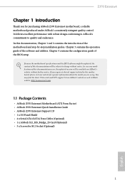
Z370 Extreme4 Chapter 1 Introduction Thank you are using. ASRock website http://www.asrock.com. 1.1 Package Contents • ASRock Z370 Extreme4 Motherboard (ATX Form Factor) • ASRock Z370 Extreme4 Quick Installation Guide • ASRock Z370 Extreme4 Support CD • 1 x I/O Panel Shield • 4 x Serial ATA (SATA) Data Cables (Optional) • 1 x ASRock SLI_HB_Bridge_2S Card (Optional) • 3 x Screws for purchasing ASRock Z370 Extreme4 motherboard, a reliable motherboard produced under ASRock's consistently stringent quality control. In this motherboard, ...
Z370 Extreme4 Chapter 1 Introduction Thank you are using. ASRock website http://www.asrock.com. 1.1 Package Contents • ASRock Z370 Extreme4 Motherboard (ATX Form Factor) • ASRock Z370 Extreme4 Quick Installation Guide • ASRock Z370 Extreme4 Support CD • 1 x I/O Panel Shield • 4 x Serial ATA (SATA) Data Cables (Optional) • 1 x ASRock SLI_HB_Bridge_2S Card (Optional) • 3 x Screws for purchasing ASRock Z370 Extreme4 motherboard, a reliable motherboard produced under ASRock's consistently stringent quality control. In this motherboard, ...

User Manual
Page 14
1.3 Motherboard Layout 1 ATX12V1 2 3 45 CPU_FAN1 CPU_OPT/ W_PUMP PS2 Keyboard /Mouse USB 3.1 Gen1 T: USB1 B: USB2 ATXPWR1 DDR4_A1 (64 bit, 288-pin module) DDR4_A2 (64 bit, 288-pin ... CT2 CT1 27 PCIE2 LAN CMOS Battery Purity SoundTM 4 PCIE3 PCIE4 M2_1 Ultra M.2 PCIe Gen3 x4 6 7 USB3_5_6 1 USB3_7_8 8 USB3_TC_1 1 9 10 SATA3_4_5 SATA3_2_3 11 SATA3_0_1 Intel Z370 12 13 SATA3_A1_A2 M2_2 PCIE5 RoHS PCIE6 HD_AUDIO1 1 CLRMOS1 1 T B1 RGB_LED 1 1 CHA_FAN2 TPMS1 CT5 CT4 CT3 CT2 CT1 Ultra M.2 PCIe Gen3 x4 BIOS_A1 BIOS_A_LED1 BIOS...
1.3 Motherboard Layout 1 ATX12V1 2 3 45 CPU_FAN1 CPU_OPT/ W_PUMP PS2 Keyboard /Mouse USB 3.1 Gen1 T: USB1 B: USB2 ATXPWR1 DDR4_A1 (64 bit, 288-pin module) DDR4_A2 (64 bit, 288-pin ... CT2 CT1 27 PCIE2 LAN CMOS Battery Purity SoundTM 4 PCIE3 PCIE4 M2_1 Ultra M.2 PCIe Gen3 x4 6 7 USB3_5_6 1 USB3_7_8 8 USB3_TC_1 1 9 10 SATA3_4_5 SATA3_2_3 11 SATA3_0_1 Intel Z370 12 13 SATA3_A1_A2 M2_2 PCIE5 RoHS PCIE6 HD_AUDIO1 1 CLRMOS1 1 T B1 RGB_LED 1 1 CHA_FAN2 TPMS1 CT5 CT4 CT3 CT2 CT1 Ultra M.2 PCIe Gen3 x4 BIOS_A1 BIOS_A_LED1 BIOS...

User Manual
Page 18
.... • In order to avoid damage from static electricity to unplug the power cord before you uninstall any motherboard settings. • Make sure to the motherboard's components, NEVER place your chassis to the chassis, please do not touch the ICs. • Whenever you handle.... • Hold components by the edges and do not overtighten the screws! Before you install the motherboard, study the configuration of the following precautions before you install motherboard components or change any components, place them on a carpet. Chapter 2 Installation This is an ATX form...
.... • In order to avoid damage from static electricity to unplug the power cord before you uninstall any motherboard settings. • Make sure to the motherboard's components, NEVER place your chassis to the chassis, please do not touch the ICs. • Whenever you handle.... • Hold components by the edges and do not overtighten the screws! Before you install the motherboard, study the configuration of the following precautions before you install motherboard components or change any components, place them on a carpet. Chapter 2 Installation This is an ATX form...

User Manual
Page 21
Z370 Extreme4 Please save and replace the cover if the processor is removed. The cover must be placed if you wish to return the motherboard for after service. 15 English
Z370 Extreme4 Please save and replace the cover if the processor is removed. The cover must be placed if you wish to return the motherboard for after service. 15 English

User Manual
Page 23
... the DIMM if you always need to install a DDR, DDR2 or DDR3 memory module into the slot at incorrect orientation. Z370 Extreme4 2.3 Installing Memory Modules (DIMM) This motherboard provides four 288-pin DDR4 (Double Data Rate 4) DIMM slots, and supports Dual Channel Memory Technology. 1. Dual Channel Memory Configuration Priority 1 2 DDR4_A1 Populated DDR4_A2 Populated...
... the DIMM if you always need to install a DDR, DDR2 or DDR3 memory module into the slot at incorrect orientation. Z370 Extreme4 2.3 Installing Memory Modules (DIMM) This motherboard provides four 288-pin DDR4 (Double Data Rate 4) DIMM slots, and supports Dual Channel Memory Technology. 1. Dual Channel Memory Configuration Priority 1 2 DDR4_A1 Populated DDR4_A2 Populated...

User Manual
Page 25
... Mode x8 N/A Three Graphics Cards in 3-Way CrossFireXTM Mode x8 x8 x4 English For a better thermal environment, please connect a chassis fan to the motherboard's chassis fan connector (CHA_FAN1, CHA_FAN2 or CHA_FAN3 ) when using multiple graphics cards. 19 Please read the documentation of the expansion card and make sure... x1 lane width cards. Before installing an expansion card, please make necessary hardware settings for PCI Express x4 lane width graphics cards. Z370 Extreme4 2.4 Expansion Slots (PCI Express Slots) There are 6 PCI Express slots on the motherboard.
... Mode x8 N/A Three Graphics Cards in 3-Way CrossFireXTM Mode x8 x8 x4 English For a better thermal environment, please connect a chassis fan to the motherboard's chassis fan connector (CHA_FAN1, CHA_FAN2 or CHA_FAN3 ) when using multiple graphics cards. 19 Please read the documentation of the expansion card and make sure... x1 lane width cards. Before installing an expansion card, please make necessary hardware settings for PCI Express x4 lane width graphics cards. Z370 Extreme4 2.4 Expansion Slots (PCI Express Slots) There are 6 PCI Express slots on the motherboard.
User Manual
Page 27
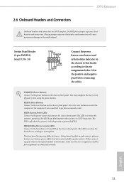
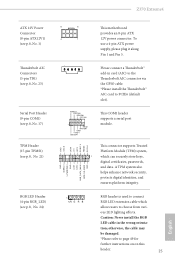
... the chassis front panel. English 21 HDLED (Hard Drive Activity LED): Connect to perform a normal restart. Z370 Extreme4 2.6 Onboard Headers and Connectors Onboard headers and connectors are matched correctly. PWRBTN (Power Button): Connect to the motherboard. Placing jumper caps over these headers and connectors. The LED is on when the hard drive is...
... the chassis front panel. English 21 HDLED (Hard Drive Activity LED): Connect to perform a normal restart. Z370 Extreme4 2.6 Onboard Headers and Connectors Onboard headers and connectors are matched correctly. PWRBTN (Power Button): Connect to the motherboard. Placing jumper caps over these headers and connectors. The LED is on when the hard drive is...

User Manual
Page 28
... be disabled. * M2_2, SATA3_4 and SATA3_5 share lanes. English 22 If either one of them is in use Intel® Z370 SATA ports (SATA3_0) for internal storage devices with up to this motherboard. Please connect the chassis power LED and the chassis speaker to 6.0 Gb/s data transfer rate. * M2_1, SATA3_0 and SATA3_1...
... be disabled. * M2_2, SATA3_4 and SATA3_5 share lanes. English 22 If either one of them is in use Intel® Z370 SATA ports (SATA3_0) for internal storage devices with up to this motherboard. Please connect the chassis power LED and the chassis speaker to 6.0 Gb/s data transfer rate. * M2_1, SATA3_0 and SATA3_1...
User Manual
Page 29
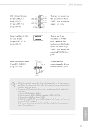
... "Recording Volume". Connect Audio_R (RIN) to OUT2_R and Audio_L (LIN) to MIC2_L. MIC_RET and OUT_RET are two headers on this motherboard. E. Connect Mic_IN (MIC) to OUT2_L. Connect Ground (GND) to the front panel audio header by the steps below: A. To...need to connect them for connecting audio devices to function correctly. B. D. Z370 Extreme4 USB 3.1 Gen1 Headers (19-pin USB3_5_6) (see p.8, No. 7) (19-pin USB3_7_8) (see p.8, No. 9) There is one Front Panel Type C USB 3.1 Gen1 Header on this motherboard. Front Panel Type C USB 3.1 Gen1 Header (26-pin USB3_TC_1) ...
... "Recording Volume". Connect Audio_R (RIN) to OUT2_R and Audio_L (LIN) to MIC2_L. MIC_RET and OUT_RET are two headers on this motherboard. E. Connect Mic_IN (MIC) to OUT2_L. Connect Ground (GND) to the front panel audio header by the steps below: A. To...need to connect them for connecting audio devices to function correctly. B. D. Z370 Extreme4 USB 3.1 Gen1 Headers (19-pin USB3_5_6) (see p.8, No. 7) (19-pin USB3_7_8) (see p.8, No. 9) There is one Front Panel Type C USB 3.1 Gen1 Header on this motherboard. Front Panel Type C USB 3.1 Gen1 Header (26-pin USB3_TC_1) ...

User Manual
Page 30
...34 Chassis Optional/Water Pump Fan Connector (4-pin CHA_FAN3/W_ PUMP) (see p.8, No. 2) FAN_SPEED_CONTROL CPU_FAN_SPEED FAN_VOLTAGE GND 1 2 34 This motherboard provides a 4-Pin CPU fan (Quiet Fan) connector. CPU Fan Connector (4-pin CPU_FAN1) (see p.8, No. 16) GND FAN_VOLTAGE FAN_SPEED FAN_SPEED_CONTROL 1 2 34 ... cooling CPU fan connector. CPU Optional/Water Pump Fan Connector (4-pin CPU_OPT/W_ PUMP) (see p.8, No. 6) 24 12 24 1 13 This motherboard provides a 24-pin ATX power connector. If you plan to connect a 3-Pin CPU fan, please connect it to Pin 1-3. To use a 20...
...34 Chassis Optional/Water Pump Fan Connector (4-pin CHA_FAN3/W_ PUMP) (see p.8, No. 2) FAN_SPEED_CONTROL CPU_FAN_SPEED FAN_VOLTAGE GND 1 2 34 This motherboard provides a 4-Pin CPU fan (Quiet Fan) connector. CPU Fan Connector (4-pin CPU_FAN1) (see p.8, No. 16) GND FAN_VOLTAGE FAN_SPEED FAN_SPEED_CONTROL 1 2 34 ... cooling CPU fan connector. CPU Optional/Water Pump Fan Connector (4-pin CPU_OPT/W_ PUMP) (see p.8, No. 6) 24 12 24 1 13 This motherboard provides a 24-pin ATX power connector. If you plan to connect a 3-Pin CPU fan, please connect it to Pin 1-3. To use a 20...
User Manual
Page 31
...B RGB header is used to connect RGB LED extension cable which can securely store keys, digital certificates, passwords, and data. ous LED lighting effects. Z370 Extreme4 ATX 12V Power Connector (8-pin ATX12V1) (see p.8, No. 1) Thunderbolt AIC Connectors (5-pin TB1) (see p.8, No. 23) Serial Port Header (9-... # S_PWRDWN # GN D LAD1 LAD2 SMB_DATA_MAIN SMB_CLK_MAIN GN D +3VS B LAD0 +3V LAD3 PCIRST # FRAM E PCICLK 8 5 4 1 This motherboard provides an 8-pin ATX 12V power connector. Caution: Never install the RGB LED cable in card (AIC) to the Thunderbolt AIC connector via the GPIO...
...B RGB header is used to connect RGB LED extension cable which can securely store keys, digital certificates, passwords, and data. ous LED lighting effects. Z370 Extreme4 ATX 12V Power Connector (8-pin ATX12V1) (see p.8, No. 1) Thunderbolt AIC Connectors (5-pin TB1) (see p.8, No. 23) Serial Port Header (9-... # S_PWRDWN # GN D LAD1 LAD2 SMB_DATA_MAIN SMB_CLK_MAIN GN D +3VS B LAD0 +3V LAD3 PCIRST # FRAM E PCICLK 8 5 4 1 This motherboard provides an 8-pin ATX 12V power connector. Caution: Never install the RGB LED cable in card (AIC) to the Thunderbolt AIC connector via the GPIO...

User Manual
Page 32
... graphics card into PCIE2 slot and the other graphics card to the PCI Express graphics cards. 26 English 2.7 SLITM and Quad SLITM Operation Guide This motherboard supports NVIDIA® SLITM and Quad SLITM (Scalable Link Interface) technology that allows you to install up to use identical SLITM-ready graphics cards that...
... graphics card into PCIE2 slot and the other graphics card to the PCI Express graphics cards. 26 English 2.7 SLITM and Quad SLITM Operation Guide This motherboard supports NVIDIA® SLITM and Quad SLITM (Scalable Link Interface) technology that allows you to install up to use identical SLITM-ready graphics cards that...

User Manual
Page 35
... will operate as 12-pipe cards while in CrossFireXTM mode. 5. Please refer to three identical PCI Express x16 graphics cards. 1. Z370 Extreme4 2.8 CrossFireXTM , 3-Way CrossFireXTM and Quad CrossFireXTM Operation Guide This motherboard supports CrossFireXTM, 3-way CrossFireXTM and Quad CrossFireXTM that allows you to install up to the AMD's website for details.) English 29...
... will operate as 12-pipe cards while in CrossFireXTM mode. 5. Please refer to three identical PCI Express x16 graphics cards. 1. Z370 Extreme4 2.8 CrossFireXTM , 3-Way CrossFireXTM and Quad CrossFireXTM Operation Guide This motherboard supports CrossFireXTM, 3-way CrossFireXTM and Quad CrossFireXTM that allows you to install up to the AMD's website for details.) English 29...

User Manual
Page 37
.... (The CrossFire Bridge is inserted to PCIE2 slot. English 31 Make sure that is provided with the graphics card you purchase, not bundled with this motherboard. Z370 Extreme4 2.8.2 Installing Three CrossFireXTM-Ready Graphics Cards Step 1 Insert one CrossFire Bridge to connect the graphics cards on PCIE2 and PCIE4 slots, and use the other...
.... (The CrossFire Bridge is inserted to PCIE2 slot. English 31 Make sure that is provided with the graphics card you purchase, not bundled with this motherboard. Z370 Extreme4 2.8.2 Installing Three CrossFireXTM-Ready Graphics Cards Step 1 Insert one CrossFire Bridge to connect the graphics cards on PCIE2 and PCIE4 slots, and use the other...

User Manual
Page 42
... D by hand. Otherwise, release the standoff by default. Step 6 Tighten the screw with a screwdriver to secure the module into the desired nut location on the motherboard. English 36 Skip Step 3 and 4 and go straight to Step 5 if you are going to be aware that the M.2 (NGFF) SSD module only fits in...
... D by hand. Otherwise, release the standoff by default. Step 6 Tighten the screw with a screwdriver to secure the module into the desired nut location on the motherboard. English 36 Skip Step 3 and 4 and go straight to Step 5 if you are going to be aware that the M.2 (NGFF) SSD module only fits in...
User Manual
Page 45
... the support CD, insert the CD into your computer. Utilities Menu The Utilities Menu shows the application software that enhance the motherboard's features. Please click Install All or follow the installation wizard to display the menu. Click on a specific item then follow... Drivers Menu The drivers compatible to install those required drivers. Therefore, the drivers you install can work properly. Z370 Extreme4 Chapter 3 Software and Utilities Operation 3.1 Installing Drivers The Support CD that comes with the motherboard contains necessary drivers and useful utilities that the...
... the support CD, insert the CD into your computer. Utilities Menu The Utilities Menu shows the application software that enhance the motherboard's features. Please click Install All or follow the installation wizard to display the menu. Click on a specific item then follow... Drivers Menu The drivers compatible to install those required drivers. Therefore, the drivers you install can work properly. Z370 Extreme4 Chapter 3 Software and Utilities Operation 3.1 Installing Drivers The Support CD that comes with the motherboard contains necessary drivers and useful utilities that the...

User Manual
Page 49
...displays the relative information. You can optimize your system and keep your motherboard up to visit the website of the selected news and know more. 43 English Z370 Extreme4 3.3 ASRock Live Update & APP Shop The ASRock Live Update & APP Shop is an online store for purchasing and downloading... software applications for your desktop to access ASRock Live Update & APP Shop *You need to be ...
...displays the relative information. You can optimize your system and keep your motherboard up to visit the website of the selected news and know more. 43 English Z370 Extreme4 3.3 ASRock Live Update & APP Shop The ASRock Live Update & APP Shop is an online store for purchasing and downloading... software applications for your desktop to access ASRock Live Update & APP Shop *You need to be ...
User Manual
Page 55
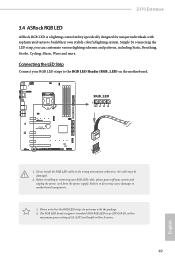
... power supply. otherwise, the cable may cause damages to the RGB LED Header (RGB_LED) on the motherboard. Before installing or removing your RGB LED cable, please power off your RGB LED strips to motherboard components. 1. Z370 Extreme4 3.4 ASRock RGB LED ASRock RGB LED is a lighting control utility specifically designed for unique individuals with a maximum power rating...
... power supply. otherwise, the cable may cause damages to the RGB LED Header (RGB_LED) on the motherboard. Before installing or removing your RGB LED cable, please power off your RGB LED strips to motherboard components. 1. Z370 Extreme4 3.4 ASRock RGB LED ASRock RGB LED is a lighting control utility specifically designed for unique individuals with a maximum power rating...

