User Manual
Page 7
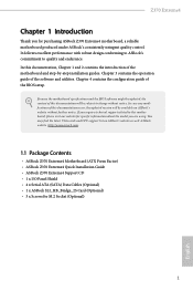
... to this documentation, Chapter 1 and 2 contains the introduction of this documentation occur, the updated version will be available on ASRock's website as well. ASRock website http://www.asrock.com. 1.1 Package Contents • ASRock Z370 Extreme4 Motherboard (ATX Form Factor) • ASRock Z370 Extreme4 Quick Installation Guide • ASRock Z370 Extreme4 Support CD • 1 x I/O Panel Shield • 4 x Serial ATA (SATA) Data Cables (Optional) •...
... to this documentation, Chapter 1 and 2 contains the introduction of this documentation occur, the updated version will be available on ASRock's website as well. ASRock website http://www.asrock.com. 1.1 Package Contents • ASRock Z370 Extreme4 Motherboard (ATX Form Factor) • ASRock Z370 Extreme4 Quick Installation Guide • ASRock Z370 Extreme4 Support CD • 1 x I/O Panel Shield • 4 x Serial ATA (SATA) Data Cables (Optional) •...

User Manual
Page 8
... supports type 2230 WiFi/BT module • 15μ Gold Contact in nonECC mode) • Max. 1.2 Specifications Platform CPU Chipset • ATX Form Factor • Supports 8th Generation Intel® CoreTM Processors (Socket 1151) • Digi Power design • 12 Power Phase design •... Supports Intel® Turbo Boost 2.0 Technology • Supports Intel® K-Series unlocked CPUs • Supports ASRock BCLK Full-range Overclocking • Intel® Z370 Memory • Dual Channel DDR4 Memory Technology • 4 x DDR4 DIMM Slots • Supports DDR4 4333+(OC)*/...
... supports type 2230 WiFi/BT module • 15μ Gold Contact in nonECC mode) • Max. 1.2 Specifications Platform CPU Chipset • ATX Form Factor • Supports 8th Generation Intel® CoreTM Processors (Socket 1151) • Digi Power design • 12 Power Phase design •... Supports Intel® Turbo Boost 2.0 Technology • Supports Intel® K-Series unlocked CPUs • Supports ASRock BCLK Full-range Overclocking • Intel® Z370 Memory • Dual Channel DDR4 Memory Technology • 4 x DDR4 DIMM Slots • Supports DDR4 4333+(OC)*/...
User Manual
Page 11
Z370 Extreme4 • 1 x Ultra M.2 Socket (M2_1), supports M Key type 2230/2242/2260/2280 M.2 SATA3 6.0 ... M.2 PCI Express module up to Gen3 x4 (32 Gb/s)** ** Supports Intel® OptaneTM Technology ** Supports NVMe SSD as boot disks ** Supports ASRock U.2 Kit Connector • 1 x COM Port Header • 1 x TPM Header • 1 x Power LED and Speaker Header •... power. * CHA_FAN1 and CHA_FAN2 can auto detect if 3-pin or 4-pin fan is in use. • 1 x 24 pin ATX Power Connector (Hi-Density Power Connector) • 1 x 8 pin 12V Power Connector (Hi-Density Power Connector) • 1 ...
Z370 Extreme4 • 1 x Ultra M.2 Socket (M2_1), supports M Key type 2230/2242/2260/2280 M.2 SATA3 6.0 ... M.2 PCI Express module up to Gen3 x4 (32 Gb/s)** ** Supports Intel® OptaneTM Technology ** Supports NVMe SSD as boot disks ** Supports ASRock U.2 Kit Connector • 1 x COM Port Header • 1 x TPM Header • 1 x Power LED and Speaker Header •... power. * CHA_FAN1 and CHA_FAN2 can auto detect if 3-pin or 4-pin fan is in use. • 1 x 24 pin ATX Power Connector (Hi-Density Power Connector) • 1 x 8 pin 12V Power Connector (Hi-Density Power Connector) • 1 ...
User Manual
Page 15
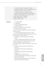
Z370 Extreme4 No. Description 1 ATX 12V Power Connector (ATX12V1) 2 CPU Fan Connector (CPU_FAN1) 3 CPU Fan / Waterpump Fan Connector (CPU_OPT/W_PUMP) 4 2 x 288-pin DDR4 DIMM Slots (DDR4_A1, DDR4_B1) 5 2 x 288-pin DDR4 DIMM Slots (DDR4_A2, DDR4_B2) 6 ATX Power Connector (ATXPWR1) 7 USB 3.1 Gen1 Header (USB3_5_6) 8 USB 3.1 Gen1 Header (USB3_7_8) 9 Front Panel Type C USB 3.1 Gen1 Header (USB3_TC_1) 10 SATA3...
Z370 Extreme4 No. Description 1 ATX 12V Power Connector (ATX12V1) 2 CPU Fan Connector (CPU_FAN1) 3 CPU Fan / Waterpump Fan Connector (CPU_OPT/W_PUMP) 4 2 x 288-pin DDR4 DIMM Slots (DDR4_A1, DDR4_B1) 5 2 x 288-pin DDR4 DIMM Slots (DDR4_A2, DDR4_B2) 6 ATX Power Connector (ATXPWR1) 7 USB 3.1 Gen1 Header (USB3_5_6) 8 USB 3.1 Gen1 Header (USB3_7_8) 9 Front Panel Type C USB 3.1 Gen1 Header (USB3_TC_1) 10 SATA3...

User Manual
Page 18
.... • Make sure to do not overtighten the screws! Pre-installation Precautions Take note of your motherboard directly on a carpet. Chapter 2 Installation This is an ATX form factor motherboard.
.... • Make sure to do not overtighten the screws! Pre-installation Precautions Take note of your motherboard directly on a carpet. Chapter 2 Installation This is an ATX form factor motherboard.

User Manual
Page 30
...21 FAN_SPEED_CONTROL CHA_FAN_SPEED FAN_VOLTAGE GND GND FAN_VOLTAGE FAN_SPEED FAN_SPEED_CONTROL Please connect fan cables to the fan connectors and match the black wire to Pin 1-3. English ATX Power Connector (24-pin ATXPWR1) (see p.8, No. 3) FAN_SPEED_CONTROL CPU_FAN_SPEED FAN_VOLTAGE GND This motherboard 4 3 provides a 4-Pin water 2 1 ... Pump Fan Connector (4-pin CPU_OPT/W_ PUMP) (see p.8, No. 6) 24 12 24 1 13 This motherboard provides a 24-pin ATX power connector. If you plan to connect a 3-Pin chassis water cooler fan, please connect it along Pin 1 and Pin 13. To use...
...21 FAN_SPEED_CONTROL CHA_FAN_SPEED FAN_VOLTAGE GND GND FAN_VOLTAGE FAN_SPEED FAN_SPEED_CONTROL Please connect fan cables to the fan connectors and match the black wire to Pin 1-3. English ATX Power Connector (24-pin ATXPWR1) (see p.8, No. 3) FAN_SPEED_CONTROL CPU_FAN_SPEED FAN_VOLTAGE GND This motherboard 4 3 provides a 4-Pin water 2 1 ... Pump Fan Connector (4-pin CPU_OPT/W_ PUMP) (see p.8, No. 6) 24 12 24 1 13 This motherboard provides a 24-pin ATX power connector. If you plan to connect a 3-Pin chassis water cooler fan, please connect it along Pin 1 and Pin 13. To use...
User Manual
Page 31
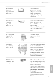
Z370 Extreme4 ATX 12V Power Connector (8-pin ATX12V1) (see p.8, No. 1) Thunderbolt AIC Connectors (5-pin TB1) (...SMB_DATA_MAIN SMB_CLK_MAIN GN D +3VS B LAD0 +3V LAD3 PCIRST # FRAM E PCICLK 8 5 4 1 This motherboard provides an 8-pin ATX 12V power connector. Caution: Never install the RGB LED cable in card (AIC) to the Thunderbolt AIC connector via the GPIO cable. ...the cable may be damaged. *Please refer to PCIE6 (default slot). ous LED lighting effects. To use a 4-pin ATX power supply, please plug it along Pin 1 and Pin 5. 1 Please connect a Thunderbolt™ add-in the wrong ...
Z370 Extreme4 ATX 12V Power Connector (8-pin ATX12V1) (see p.8, No. 1) Thunderbolt AIC Connectors (5-pin TB1) (...SMB_DATA_MAIN SMB_CLK_MAIN GN D +3VS B LAD0 +3V LAD3 PCIRST # FRAM E PCICLK 8 5 4 1 This motherboard provides an 8-pin ATX 12V power connector. Caution: Never install the RGB LED cable in card (AIC) to the Thunderbolt AIC connector via the GPIO cable. ...the cable may be damaged. *Please refer to PCIE6 (default slot). ous LED lighting effects. To use a 4-pin ATX power supply, please plug it along Pin 1 and Pin 5. 1 Please connect a Thunderbolt™ add-in the wrong ...