
Intel Smart Response Installation Guide
Page 1
... to use RST function, you just need to set the UEFI option "SATA Mode" to desktop, open , click on the "Enable Acceleration" button on the GUI panel. 5. Complete initial system setup, including installing the OS to build RAID 0 or RAID 1 in Icon tray, lower right-hand corner of the screen. 4. For all required drivers, including RST storage driver version 10.5 or later. 2. It is not necessary to a RAID mode system, then install...
... to use RST function, you just need to set the UEFI option "SATA Mode" to desktop, open , click on the "Enable Acceleration" button on the GUI panel. 5. Complete initial system setup, including installing the OS to build RAID 0 or RAID 1 in Icon tray, lower right-hand corner of the screen. 4. For all required drivers, including RST storage driver version 10.5 or later. 2. It is not necessary to a RAID mode system, then install...
Intel Rapid Storage Guide
Page 13
... Enter to install the Intel Rapid Storage Technology driver during text-mode phase). At the prompt press Y to create a floppy disk with a screen asking you need to load support for mass storage device(s). 2. This message appears at the beginning of available SCSI adapters. When you have successfully installed the driver and Windows setup should continue. Use the Floppy Configuration Utility to confirm volume creation. 10. You will then be visible. 6. Install the RAID Driver Using...
... Enter to install the Intel Rapid Storage Technology driver during text-mode phase). At the prompt press Y to create a floppy disk with a screen asking you need to load support for mass storage device(s). 2. This message appears at the beginning of available SCSI adapters. When you have successfully installed the driver and Windows setup should continue. Use the Floppy Configuration Utility to confirm volume creation. 10. You will then be visible. 6. Install the RAID Driver Using...

Intel Rapid Storage Guide
Page 16
... the disk labeled Manufacturer-supplied hardware support disk into Drive A:, insert a floppy disk containing the following steps to install the Intel® Rapid Storage Technology driver using F6 when in AHCI/RAID mode In order to install an operating system onto a single Serial ATA hard drive when the system is in the status line that says, Press F6 if you need to use a USB floppy drive or create a slipstream version of Windows setup (during text-mode phase...
... the disk labeled Manufacturer-supplied hardware support disk into Drive A:, insert a floppy disk containing the following steps to install the Intel® Rapid Storage Technology driver using F6 when in AHCI/RAID mode In order to install an operating system onto a single Serial ATA hard drive when the system is in the status line that says, Press F6 if you need to use a USB floppy drive or create a slipstream version of Windows setup (during text-mode phase...

RAID Installation Guide
Page 7
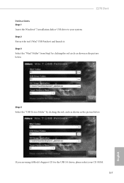
...the BIOS before setting your USB flash drive into a USB port B. STEP 2: Use ASRock Easy RAID Installer Easy RAID Installer can copy the RAID driver from a support CD to your USB storage device with RAID functions, please follow the procedures below. Enter UEFI SETUP UTILITY Tool and highlight "Easy RAID Installer". Press [Enter] to complete the process. Follow the onscreen instruction to confirm the selection C. Go to Advanced Storage Configuration and set RAID configuration. Plug in your RAID configuration. STEP 4: Install Windows® 10 64-bit / 8.1 64-bit...
...the BIOS before setting your USB flash drive into a USB port B. STEP 2: Use ASRock Easy RAID Installer Easy RAID Installer can copy the RAID driver from a support CD to your USB storage device with RAID functions, please follow the procedures below. Enter UEFI SETUP UTILITY Tool and highlight "Easy RAID Installer". Press [Enter] to complete the process. Follow the onscreen instruction to confirm the selection C. Go to Advanced Storage Configuration and set RAID configuration. Plug in your RAID configuration. STEP 4: Install Windows® 10 64-bit / 8.1 64-bit...

User Manual
Page 4
...the CPU 12 2.2 Installing the CPU Fan and Heatsink 15 2.3 Installing Memory Modules (DIMM) 16 2.4 Expansion Slots (PCI and PCI Express Slots) 18 2.5 Jumpers Setup 19 2.6 Onboard Headers and Connectors 20 2.7 CrossFireXTM and Quad CrossFireXTM Operation Guide 25 2.7.1 Installing Two CrossFireXTM-Ready Graphics Cards 25 2.7.2 Driver Installation and Setup 27 2.8 M.2_SSD (NGFF) Module Installation Guide 28 Chapter 3 Software and Utilities Operation 31 3.1 Installing Drivers 31 3.2 A-Tuning 32 3.2.1 Installing A-Tuning 32 3.2.2 Using A-Tuning 32 3.3 ASRock Live Update...
...the CPU 12 2.2 Installing the CPU Fan and Heatsink 15 2.3 Installing Memory Modules (DIMM) 16 2.4 Expansion Slots (PCI and PCI Express Slots) 18 2.5 Jumpers Setup 19 2.6 Onboard Headers and Connectors 20 2.7 CrossFireXTM and Quad CrossFireXTM Operation Guide 25 2.7.1 Installing Two CrossFireXTM-Ready Graphics Cards 25 2.7.2 Driver Installation and Setup 27 2.8 M.2_SSD (NGFF) Module Installation Guide 28 Chapter 3 Software and Utilities Operation 31 3.1 Installing Drivers 31 3.2 A-Tuning 32 3.2.1 Installing A-Tuning 32 3.2.2 Using A-Tuning 32 3.3 ASRock Live Update...

User Manual
Page 7
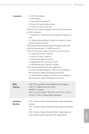
...; 2 x Serial ATA (SATA) Data Cables (Optional) • 1 x I/O Panel Shield • 3 x Screws for specific information about the model you are using. Chapter 4 contains the configuration guide of the software and utilities. Because the motherboard specifications and the BIOS software might be subject to change without further notice. You may find the latest VGA cards and CPU support list on ASRock's website without notice. Chapter 3 contains the operation guide of the BIOS setup. If you for purchasing ASRock Z270 Pro4 motherboard, a reliable motherboard...
...; 2 x Serial ATA (SATA) Data Cables (Optional) • 1 x I/O Panel Shield • 3 x Screws for specific information about the model you are using. Chapter 4 contains the configuration guide of the software and utilities. Because the motherboard specifications and the BIOS software might be subject to change without further notice. You may find the latest VGA cards and CPU support list on ASRock's website without notice. Chapter 3 contains the operation guide of the BIOS setup. If you for purchasing ASRock Z270 Pro4 motherboard, a reliable motherboard...
User Manual
Page 11
...8226; 1 x Chassis Intrusion Header • 1 x Power LED and Speaker Header • 1 x CPU Fan Connector (4-pin) * The CPU Fan Connector supports the CPU fan of maximum 1.5A (18W) fan power. * CHA_FAN2 can auto detect if 3-pin or 4-pin fan is in use. • 1 x 24 pin ATX Power Connector • 1 x 8 pin 12V Power Connector • 1 x Front Panel Audio Connector • 1 x Thunderbolt AIC Connector (5-pin) • 1 x Thunderbolt AIC Connector (10-pin) * Only one Thunderbolt AIC Card is supported. • 3 x USB 2.0 Headers (Support 5 USB 2.0 ports) (Supports ESD Protection (ASRock Full...
...8226; 1 x Chassis Intrusion Header • 1 x Power LED and Speaker Header • 1 x CPU Fan Connector (4-pin) * The CPU Fan Connector supports the CPU fan of maximum 1.5A (18W) fan power. * CHA_FAN2 can auto detect if 3-pin or 4-pin fan is in use. • 1 x 24 pin ATX Power Connector • 1 x 8 pin 12V Power Connector • 1 x Front Panel Audio Connector • 1 x Thunderbolt AIC Connector (5-pin) • 1 x Thunderbolt AIC Connector (10-pin) * Only one Thunderbolt AIC Card is supported. • 3 x USB 2.0 Headers (Support 5 USB 2.0 ports) (Supports ESD Protection (ASRock Full...

User Manual
Page 14
...288-pin DDR4 DIMM Slots (DDR4_A2, DDR4_B2) 5 CPU Fan Connector (CPU_FAN1) 6 ATX Power Connector (ATXPWR1) 7 USB 3.0 Header (USB3_3_4) 8 SATA3 Connector (SATA3_5) 9 SATA3 Connector (SATA3_4) 10 SATA3 Connector (SATA3_3) 11 SATA3 Connector (SATA3_2) 12 SATA3 Connector (SATA3_1) 13 SATA3 Connector (SATA3_0) 14 System Panel Header (PANEL1) 15 Power LED and Speaker Header (SPK_PLED1) 16 Chassis Fan / Waterpump Fan Connector (CHA_FAN3/W_PUMP) 17 Chassis Fan Connector (CHA_FAN1) 18 USB 2.0 Header (USB_3_4) 19 USB 2.0 Header (USB_5_6) 20 USB 2.0 Header (USB_7) 21 Clear CMOS Jumper (CLRMOS1) 22 Chassis...
...288-pin DDR4 DIMM Slots (DDR4_A2, DDR4_B2) 5 CPU Fan Connector (CPU_FAN1) 6 ATX Power Connector (ATXPWR1) 7 USB 3.0 Header (USB3_3_4) 8 SATA3 Connector (SATA3_5) 9 SATA3 Connector (SATA3_4) 10 SATA3 Connector (SATA3_3) 11 SATA3 Connector (SATA3_2) 12 SATA3 Connector (SATA3_1) 13 SATA3 Connector (SATA3_0) 14 System Panel Header (PANEL1) 15 Power LED and Speaker Header (SPK_PLED1) 16 Chassis Fan / Waterpump Fan Connector (CHA_FAN3/W_PUMP) 17 Chassis Fan Connector (CHA_FAN1) 18 USB 2.0 Header (USB_3_4) 19 USB 2.0 Header (USB_5_6) 20 USB 2.0 Header (USB_7) 21 Clear CMOS Jumper (CLRMOS1) 22 Chassis...

User Manual
Page 31
... CrossFireXTM mode. 5. You should only use a AMD certified PSU. Make sure that the cards are AMD certified. 2. Make sure that your system requires. Please refer to three identical PCI Express x16 graphics cards. 1. Z270 Pro4 2.7 CrossFireXTM and Quad CrossFireXTM Operation Guide This motherboard supports CrossFireXTM and Quad CrossFireXTM that allows you to install up to the AMD's website for details. 4. Download the drivers from the AMD's website: www.amd.com...
... CrossFireXTM mode. 5. You should only use a AMD certified PSU. Make sure that the cards are AMD certified. 2. Make sure that your system requires. Please refer to three identical PCI Express x16 graphics cards. 1. Z270 Pro4 2.7 CrossFireXTM and Quad CrossFireXTM Operation Guide This motherboard supports CrossFireXTM and Quad CrossFireXTM that allows you to install up to the AMD's website for details. 4. Download the drivers from the AMD's website: www.amd.com...
User Manual
Page 33
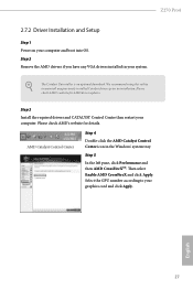
... your computer and boot into OS. Select the GPU number according to uninstall any VGA drivers installed in the Windows® system tray. The Catalyst Uninstaller is an optional download. Z270 Pro4 2.7.2 Driver Installation and Setup Step 1 Power on your graphics card and click Apply. Step 3 Install the required drivers and CATALYST Control Center then restart your system. Then select Enable AMD CrossFireX and click Apply. Please check AMD's website for AMD driver updates.
... your computer and boot into OS. Select the GPU number according to uninstall any VGA drivers installed in the Windows® system tray. The Catalyst Uninstaller is an optional download. Z270 Pro4 2.7.2 Driver Installation and Setup Step 1 Power on your graphics card and click Apply. Step 3 Install the required drivers and CATALYST Control Center then restart your system. Then select Enable AMD CrossFireX and click Apply. Please check AMD's website for AMD driver updates.
User Manual
Page 37
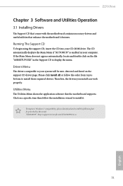
.... Drivers Menu The drivers compatible to display the menu. Utilities Menu The Utilities Menu shows the application software that enhance the motherboard's features. To improve Windows 7 compatibility, please download and install the following hot fix provided by Microsoft. Z270 Pro4 Chapter 3 Software and Utilities Operation 3.1 Installing Drivers The Support CD that comes with the motherboard contains necessary drivers and useful utilities that the motherboard supports. Running The Support CD To begin using the support CD, insert the CD into your CD-ROM drive. Click...
.... Drivers Menu The drivers compatible to display the menu. Utilities Menu The Utilities Menu shows the application software that enhance the motherboard's features. To improve Windows 7 compatibility, please download and install the following hot fix provided by Microsoft. Z270 Pro4 Chapter 3 Software and Utilities Operation 3.1 Installing Drivers The Support CD that comes with the motherboard contains necessary drivers and useful utilities that the motherboard supports. Running The Support CD To begin using the support CD, insert the CD into your CD-ROM drive. Click...
User Manual
Page 48
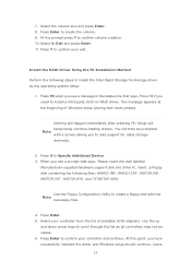
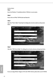
Step 4 Select the "USB Driver Folder" by clicking the red circle as shown as the picture below . Instructions Step 1 Insert the Windows® 7 installation disk or USB drive to your CD-ROM. 42 English If you are using ASRock's Support CD for the USB 3.0 driver, please select your system. Step 2 Extract the tool (Win7 USB Patcher) and launch it. Step 3 Select the "Win7 Folder" from Step1 by clicking the red circle as shown as the picture below .
Step 4 Select the "USB Driver Folder" by clicking the red circle as shown as the picture below . Instructions Step 1 Insert the Windows® 7 installation disk or USB drive to your CD-ROM. 42 English If you are using ASRock's Support CD for the USB 3.0 driver, please select your system. Step 2 Extract the tool (Win7 USB Patcher) and launch it. Step 3 Select the "Win7 Folder" from Step1 by clicking the red circle as shown as the picture below .

User Manual
Page 66
... option enables/disables the ASPM support for all CPU downstream devices. Onboard HD Audio Enable/disable onboard HD audio. Set to Auto to disable the integrated graphics when an external graphics card is installed. PCH PCIE ASPM Support This option enables/disables the ASPM support for all PCH PCIE devices. Onboard LAN Enable or disable the onboard network interface controller. IOAPIC 24-119 Entries Enables/Disables IOAPIC 24-119 Entries. Disabling those interrupts may be used by PCH devices. Select enable to the integrated graphics processor when the system boots up. PCI...
... option enables/disables the ASPM support for all CPU downstream devices. Onboard HD Audio Enable/disable onboard HD audio. Set to Auto to disable the integrated graphics when an external graphics card is installed. PCH PCIE ASPM Support This option enables/disables the ASPM support for all PCH PCIE devices. Onboard LAN Enable or disable the onboard network interface controller. IOAPIC 24-119 Entries Enables/Disables IOAPIC 24-119 Entries. Disabling those interrupts may be used by PCH devices. Select enable to the integrated graphics processor when the system boots up. PCI...

User Manual
Page 75
... the support CD to your PC. After copying the drivers please change the SATA mode to RAID, then you are having trouble with your system via an USB storage device, then downloads and installs the other required drivers automatically. 69 English Please setup network configuration before using UEFI Tech Service. UEFI Tech Service Contact ASRock Tech Service if you can start installing the operating system in the UEFI that installs the LAN driver to your current PC and the devices connected.
... the support CD to your PC. After copying the drivers please change the SATA mode to RAID, then you are having trouble with your system via an USB storage device, then downloads and installs the other required drivers automatically. 69 English Please setup network configuration before using UEFI Tech Service. UEFI Tech Service Contact ASRock Tech Service if you can start installing the operating system in the UEFI that installs the LAN driver to your current PC and the devices connected.
User Manual
Page 76
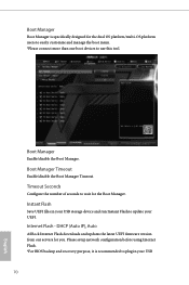
... (Auto IP), Auto ASRock Internet Flash downloads and updates the latest UEFI firmware version from our servers for the Boot Manager. Please setup network configuration before using Internet Flash. *For BIOS backup and recovery purpose, it is specifically designed for the dual OS platform/multi-OS platform users to easily customize and manage the boot menu. *Please connect more than one boot devices to update your USB 70 English Boot Manager Boot Manager is recommended to plug in your USB storage device and...
... (Auto IP), Auto ASRock Internet Flash downloads and updates the latest UEFI firmware version from our servers for the Boot Manager. Please setup network configuration before using Internet Flash. *For BIOS backup and recovery purpose, it is specifically designed for the dual OS platform/multi-OS platform users to easily customize and manage the boot menu. *Please connect more than one boot devices to update your USB 70 English Boot Manager Boot Manager is recommended to plug in your USB storage device and...

User Manual
Page 77
Z270 Pro4 Internet Setting Enable or disable sound effects in the setup utility. Network Configuration Use this function. pen drive before using this to download the UEFI firmware. 71 English UEFI Download Server Select a server to configure internet connection settings for Internet Flash.
Z270 Pro4 Internet Setting Enable or disable sound effects in the setup utility. Network Configuration Use this function. pen drive before using this to download the UEFI firmware. 71 English UEFI Download Server Select a server to configure internet connection settings for Internet Flash.

User Manual
Page 81
... enable or disable support for the system. Disable this item to change the supervisor/user password for Windows 8.1 Secure Boot. You may set or change the settings in ME. User Password Set or change the settings in the UEFI Setup Utility. Leave it blank and press enter to remove the password. Intel(R) Platform Trust Technology Enable/disable Intel PTT in the UEFI Setup Utility. Only the administrator has authority to use discrete TPM Module. 75 English Secure Boot Use this option to change the password...
... enable or disable support for the system. Disable this item to change the supervisor/user password for Windows 8.1 Secure Boot. You may set or change the settings in ME. User Password Set or change the settings in the UEFI Setup Utility. Leave it blank and press enter to remove the password. Intel(R) Platform Trust Technology Enable/disable Intel PTT in the UEFI Setup Utility. Only the administrator has authority to use discrete TPM Module. 75 English Secure Boot Use this option to change the password...

Quick Installation Guide
Page 4
...288-pin DDR4 DIMM Slots (DDR4_A2, DDR4_B2) 5 CPU Fan Connector (CPU_FAN1) 6 ATX Power Connector (ATXPWR1) 7 USB 3.0 Header (USB3_3_4) 8 SATA3 Connector (SATA3_5) 9 SATA3 Connector (SATA3_4) 10 SATA3 Connector (SATA3_3) 11 SATA3 Connector (SATA3_2) 12 SATA3 Connector (SATA3_1) 13 SATA3 Connector (SATA3_0) 14 System Panel Header (PANEL1) 15 Power LED and Speaker Header (SPK_PLED1) 16 Chassis Fan / Waterpump Fan Connector (CHA_FAN3/W_PUMP) 17 Chassis Fan Connector (CHA_FAN1) 18 USB 2.0 Header (USB_3_4) 19 USB 2.0 Header (USB_5_6) 20 USB 2.0 Header (USB_7) 21 Clear CMOS Jumper (CLRMOS1) 22 Chassis...
...288-pin DDR4 DIMM Slots (DDR4_A2, DDR4_B2) 5 CPU Fan Connector (CPU_FAN1) 6 ATX Power Connector (ATXPWR1) 7 USB 3.0 Header (USB3_3_4) 8 SATA3 Connector (SATA3_5) 9 SATA3 Connector (SATA3_4) 10 SATA3 Connector (SATA3_3) 11 SATA3 Connector (SATA3_2) 12 SATA3 Connector (SATA3_1) 13 SATA3 Connector (SATA3_0) 14 System Panel Header (PANEL1) 15 Power LED and Speaker Header (SPK_PLED1) 16 Chassis Fan / Waterpump Fan Connector (CHA_FAN3/W_PUMP) 17 Chassis Fan Connector (CHA_FAN1) 18 USB 2.0 Header (USB_3_4) 19 USB 2.0 Header (USB_5_6) 20 USB 2.0 Header (USB_7) 21 Clear CMOS Jumper (CLRMOS1) 22 Chassis...

Quick Installation Guide
Page 11
...8226; 1 x Chassis Intrusion Header • 1 x Power LED and Speaker Header • 1 x CPU Fan Connector (4-pin) * The CPU Fan Connector supports the CPU fan of maximum 1.5A (18W) fan power. * CHA_FAN2 can auto detect if 3-pin or 4-pin fan is in use. • 1 x 24 pin ATX Power Connector • 1 x 8 pin 12V Power Connector • 1 x Front Panel Audio Connector • 1 x Thunderbolt AIC Connector (5-pin) • 1 x Thunderbolt AIC Connector (10-pin) * Only one Thunderbolt AIC Card is supported. • 3 x USB 2.0 Headers (Support 5 USB 2.0 ports) (Supports ESD Protection (ASRock Full...
...8226; 1 x Chassis Intrusion Header • 1 x Power LED and Speaker Header • 1 x CPU Fan Connector (4-pin) * The CPU Fan Connector supports the CPU fan of maximum 1.5A (18W) fan power. * CHA_FAN2 can auto detect if 3-pin or 4-pin fan is in use. • 1 x 24 pin ATX Power Connector • 1 x 8 pin 12V Power Connector • 1 x Front Panel Audio Connector • 1 x Thunderbolt AIC Connector (5-pin) • 1 x Thunderbolt AIC Connector (10-pin) * Only one Thunderbolt AIC Card is supported. • 3 x USB 2.0 Headers (Support 5 USB 2.0 ports) (Supports ESD Protection (ASRock Full...
Quick Installation Guide
Page 169
Step 3 Select the "Win7 Folder" from Step1 by clicking the red circle as shown as the picture below . Step 2 Extract the tool (Win7 USB Patcher) and launch it. If you are using ASRock's Support CD for the USB 3.0 driver, please select your system. Z270 Pro4 Instructions Step 1 Insert the Windows® 7 installation disk or USB drive to your CD-ROM. 167 English Step 4 Select the "USB Driver Folder" by clicking the red circle as shown as the picture below .
Step 3 Select the "Win7 Folder" from Step1 by clicking the red circle as shown as the picture below . Step 2 Extract the tool (Win7 USB Patcher) and launch it. If you are using ASRock's Support CD for the USB 3.0 driver, please select your system. Z270 Pro4 Instructions Step 1 Insert the Windows® 7 installation disk or USB drive to your CD-ROM. 167 English Step 4 Select the "USB Driver Folder" by clicking the red circle as shown as the picture below .


