User Manual
Page 25
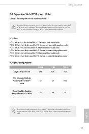
... used for PCI Express x1 lane width cards. Please read the documentation of the expansion card and make sure that the power supply is switched off or the power cord is used for PCI Express x16 lane width graphics cards. PCIE3 (PCIe 3.0 x1 slot) is unplugged. PCIe Slot... used for PCI Express x8 lane width graphics cards. PCIE5 (PCIe 3.0 x1 slot) is used for the card before you start the installation. Z270 Extreme4 2.4 Expansion Slots (PCI Express Slots) There are 6 PCI Express slots on the motherboard. Before installing an expansion card, please make necessary hardware ...
... used for PCI Express x1 lane width cards. Please read the documentation of the expansion card and make sure that the power supply is switched off or the power cord is used for PCI Express x16 lane width graphics cards. PCIE3 (PCIe 3.0 x1 slot) is unplugged. PCIe Slot... used for PCI Express x8 lane width graphics cards. PCIE5 (PCIe 3.0 x1 slot) is used for the card before you start the installation. Z270 Extreme4 2.4 Expansion Slots (PCI Express Slots) There are 6 PCI Express slots on the motherboard. Before installing an expansion card, please make necessary hardware ...
User Manual
Page 27
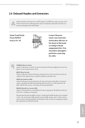
Z270 Extreme4 2.6 Onboard Headers and Connectors Onboard headers and connectors are matched correctly. Note the positive and negative pins before connecting the cables. The LED keeps blinking ... panel module to perform a normal restart. English 21 System Panel Header (9-pin PANEL1) (see p.8, No. 14) PLED+ PLEDPWRBTN# GND 1 GND RESET# GND HDLEDHDLED+ Connect the power switch, reset switch and system status indicator on the chassis to this header, make sure the wire assignments and the pin assignments are NOT jumpers. PWRBTN...
Z270 Extreme4 2.6 Onboard Headers and Connectors Onboard headers and connectors are matched correctly. Note the positive and negative pins before connecting the cables. The LED keeps blinking ... panel module to perform a normal restart. English 21 System Panel Header (9-pin PANEL1) (see p.8, No. 14) PLED+ PLEDPWRBTN# GND 1 GND RESET# GND HDLEDHDLED+ Connect the power switch, reset switch and system status indicator on the chassis to this header, make sure the wire assignments and the pin assignments are NOT jumpers. PWRBTN...
User Manual
Page 65
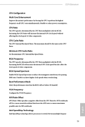
...power consumption . AVX is determined by the CPU Ratio multiplied with the BCLK. Disable to ensure maximum possible ratio for AVX workloads. Intel SpeedStep Technology Intel SpeedStep technology allows processors to perform the highest frequency on all CPU cores simultaneously. Z270 Extreme4... CPU Configuration Multi Core Enhancement Improve the system's performance by forcing the CPU to switch between multiple frequen- 59 English AVX Ratio Offset AVX Ratio Offset specifies ...
...power consumption . AVX is determined by the CPU Ratio multiplied with the BCLK. Disable to ensure maximum possible ratio for AVX workloads. Intel SpeedStep Technology Intel SpeedStep technology allows processors to perform the highest frequency on all CPU cores simultaneously. Z270 Extreme4... CPU Configuration Multi Core Enhancement Improve the system's performance by forcing the CPU to switch between multiple frequen- 59 English AVX Ratio Offset AVX Ratio Offset specifies ...


