
User Manual
Page 2
... with Part 15 of merchantability or itness for a particular purpose. CALIFORNIA, USA ONLY he Lithium battery adopted on this motherboard contains Perchlorate, a toxic substance controlled in this documentation may or may not be registered trademarks or copyrights of their respective...documentation may appear in advance. "Perchlorate Material-special handling may cause undesired operation. Version 1.0 Published September 2015 Copyright©2015 ASRock INC. In no responsibility for identiication or explanation and to the owners' beneit, without notice, and should not be reproduced,...
... with Part 15 of merchantability or itness for a particular purpose. CALIFORNIA, USA ONLY he Lithium battery adopted on this motherboard contains Perchlorate, a toxic substance controlled in this documentation may or may not be registered trademarks or copyrights of their respective...documentation may appear in advance. "Perchlorate Material-special handling may cause undesired operation. Version 1.0 Published September 2015 Copyright©2015 ASRock INC. In no responsibility for identiication or explanation and to the owners' beneit, without notice, and should not be reproduced,...
User Manual
Page 4
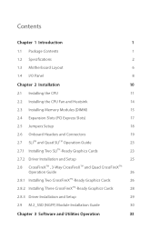
Contents Chapter 1 Introduction 1 1.1 Package Contents 1 1.2 Speciications 2 1.3 Motherboard Layout 6 1.4 I/O Panel 8 Chapter 2 Installation 10 2.1 Installing the CPU 11 2.2 Installing the CPU Fan and Heatsink 14 2.3 Installing Memory Modules (DIMM) 15 2.4 Expansion Slots (PCI Express ...
Contents Chapter 1 Introduction 1 1.1 Package Contents 1 1.2 Speciications 2 1.3 Motherboard Layout 6 1.4 I/O Panel 8 Chapter 2 Installation 10 2.1 Installing the CPU 11 2.2 Installing the CPU Fan and Heatsink 14 2.3 Installing Memory Modules (DIMM) 15 2.4 Expansion Slots (PCI Express ...
User Manual
Page 7
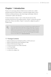
... cards and CPU support list on ASRock's website without notice. ASRock website http://www.asrock.com. 1.1 Package Contents • ASRock Z170M Extreme4 Motherboard (Micro ATX Form Factor) • ASRock Z170M Extreme4 Quick Installation Guide • ASRock Z170M Extreme4 Support CD • 2 x Serial ATA (SATA) Data Cables (Optional) • 1 x I/O Panel Shield • 1 x Screw for purchasing ASRock Z170M Extreme4 motherboard, a reliable motherboard produced under ASRock's consistently stringent quality control. In case...
... cards and CPU support list on ASRock's website without notice. ASRock website http://www.asrock.com. 1.1 Package Contents • ASRock Z170M Extreme4 Motherboard (Micro ATX Form Factor) • ASRock Z170M Extreme4 Quick Installation Guide • ASRock Z170M Extreme4 Support CD • 2 x Serial ATA (SATA) Data Cables (Optional) • 1 x I/O Panel Shield • 1 x Screw for purchasing ASRock Z170M Extreme4 motherboard, a reliable motherboard produced under ASRock's consistently stringent quality control. In case...
User Manual
Page 12
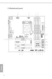
1.3 Motherboard Layout 1 2 ATX12V1 CPU_FAN1 34 PS2 Keyboard /Mouse USB 3.0 T: USB1 B: USB2 DVI1 DDR4_A1 (64 bit, 288-pin module) DDR4_A2 (64 bit, 288-pin module) DDR4_B1 (64 ... 3.0 T: USB3 B: USB4 Top: RJ-45 Top: Central/Bass LINE IN Center: REAR SPK Bottom: Optical SPDIF Top: Center: FRONT Bottom: MIC IN CHA_FAN1 CMOS Battery Z170M Extreme4 21 PCIE1 PCI Express 3.0 PCIE2 CT4 CT3 CT2 RoHS PCIE3 PCIE4 HD_AUDIO1 1 COM1 1 20 19 M2_1 5 CHA_FAN2 6 7 8 SATA3_1 SATA3_0 9 10 SATA3_3 SATA3_2 Intel 11 Z170...
1.3 Motherboard Layout 1 2 ATX12V1 CPU_FAN1 34 PS2 Keyboard /Mouse USB 3.0 T: USB1 B: USB2 DVI1 DDR4_A1 (64 bit, 288-pin module) DDR4_A2 (64 bit, 288-pin module) DDR4_B1 (64 ... 3.0 T: USB3 B: USB4 Top: RJ-45 Top: Central/Bass LINE IN Center: REAR SPK Bottom: Optical SPDIF Top: Center: FRONT Bottom: MIC IN CHA_FAN1 CMOS Battery Z170M Extreme4 21 PCIE1 PCI Express 3.0 PCIE2 CT4 CT3 CT2 RoHS PCIE3 PCIE4 HD_AUDIO1 1 COM1 1 20 19 M2_1 5 CHA_FAN2 6 7 8 SATA3_1 SATA3_0 9 10 SATA3_3 SATA3_2 Intel 11 Z170...
User Manual
Page 16
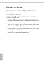
...Installation his is a Micro ATX form factor motherboard. Failure to use a grounded wrist strap or touch a safety grounded object before installing or removing the motherboard components. Doing so may cause physical injuries and damages to motherboard components. • In order to avoid ...damage from static electricity to the motherboard's components, NEVER place your chassis to ensure that comes ...
...Installation his is a Micro ATX form factor motherboard. Failure to use a grounded wrist strap or touch a safety grounded object before installing or removing the motherboard components. Doing so may cause physical injuries and damages to motherboard components. • In order to avoid ...damage from static electricity to the motherboard's components, NEVER place your chassis to ensure that comes ...
User Manual
Page 19
he cover must be placed if you wish to return the motherboard for ater service. 13 English Z170M Extreme4 Please save and replace the cover if the processor is removed.
he cover must be placed if you wish to return the motherboard for ater service. 13 English Z170M Extreme4 Please save and replace the cover if the processor is removed.
User Manual
Page 21
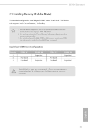
... slot; It is unable to install identical (the same brand, speed, size and chip-type) DDR4 DIMM pairs. 2. otherwise, this motherboard and DIMM may be damaged. Dual Channel Memory Coniguration Priority 1 2 3 DDR4_A1 Populated Populated DDR4_A2 Populated Populated DDR4_B1 Populated Populated DDR4_B2 Populated ... not allowed to install a DDR, DDR2 or DDR3 memory module into the slot at incorrect orientation. Z170M Extreme4 2.3 Installing Memory Modules (DIMM) his motherboard provides four 288-pin DDR4 (Double Data Rate 4) DIMM slots, and supports Dual Channel Memory Technology. 1.
... slot; It is unable to install identical (the same brand, speed, size and chip-type) DDR4 DIMM pairs. 2. otherwise, this motherboard and DIMM may be damaged. Dual Channel Memory Coniguration Priority 1 2 3 DDR4_A1 Populated Populated DDR4_A2 Populated Populated DDR4_B1 Populated Populated DDR4_B2 Populated ... not allowed to install a DDR, DDR2 or DDR3 memory module into the slot at incorrect orientation. Z170M Extreme4 2.3 Installing Memory Modules (DIMM) his motherboard provides four 288-pin DDR4 (Double Data Rate 4) DIMM slots, and supports Dual Channel Memory Technology. 1.
User Manual
Page 23
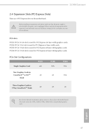
... or SLITM x8 Mode x8 N/A hree Graphics Cards in 3-Way CrossFireXTM Mode x8 x8 x4 For a better thermal environment, please connect a chassis fan to the motherboard's chassis fan connector (CHA_FAN1 or CHA_FAN2) when using multiple graphics cards. Z170M Extreme4 2.4 Expansion Slots (PCI Express Slots) here are 4 PCI Express slots on the...
... or SLITM x8 Mode x8 N/A hree Graphics Cards in 3-Way CrossFireXTM Mode x8 x8 x4 For a better thermal environment, please connect a chassis fan to the motherboard's chassis fan connector (CHA_FAN1 or CHA_FAN2) when using multiple graphics cards. Z170M Extreme4 2.4 Expansion Slots (PCI Express Slots) here are 4 PCI Express slots on the...
User Manual
Page 25
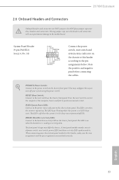
...when the system is in S4 sleep state or powered of power switch, reset switch, power LED, hard drive activity LED, speaker and etc. Z170M Extreme4 2.6 Onboard Headers and Connectors Onboard headers and connectors are matched correctly. RESET (Reset Switch): Connect to this header, make sure the wire assignments... the system is on the chassis front panel. Press the reset switch to restart the computer if the computer freezes and fails to the motherboard. he front panel design may conigure the way to the power switch on the chassis front panel. he LED is operating. A front...
...when the system is in S4 sleep state or powered of power switch, reset switch, power LED, hard drive activity LED, speaker and etc. Z170M Extreme4 2.6 Onboard Headers and Connectors Onboard headers and connectors are matched correctly. RESET (Reset Switch): Connect to this header, make sure the wire assignments... the system is on the chassis front panel. Press the reset switch to restart the computer if the computer freezes and fails to the motherboard. he front panel design may conigure the way to the power switch on the chassis front panel. he LED is operating. A front...
User Manual
Page 26
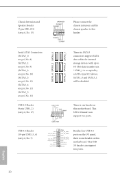
...) (see p.6, No. 12) SATA3_4 SATA3_2 SATA3_0 SATA3_5 SATA3_3 SATA3_1 hese six SATA3 connectors support SATA data cables for internal storage devices with up to this motherboard. English 20 USB 3.0 Header (19-pin USB3_5_6) (see p.6, No. 17) USB_PWR PP+ GND DUMMY 1 GND P+ PUSB_PWR here is occupied by a SATA-type M.2 device, ... 1 SIGNAL GND DUMMY Please connect the chassis intrusion and the chassis speaker to 6.0 Gb/s data transfer rate. * If M2_1 is one header on this motherboard. his USB 3.0 header can support two ports. his USB 2.0 header can support two ports.
...) (see p.6, No. 12) SATA3_4 SATA3_2 SATA3_0 SATA3_5 SATA3_3 SATA3_1 hese six SATA3 connectors support SATA data cables for internal storage devices with up to this motherboard. English 20 USB 3.0 Header (19-pin USB3_5_6) (see p.6, No. 17) USB_PWR PP+ GND DUMMY 1 GND P+ PUSB_PWR here is occupied by a SATA-type M.2 device, ... 1 SIGNAL GND DUMMY Please connect the chassis intrusion and the chassis speaker to 6.0 Gb/s data transfer rate. * If M2_1 is one header on this motherboard. his USB 3.0 header can support two ports. his USB 2.0 header can support two ports.
User Manual
Page 27
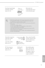
... header by the steps below: A. Connect Mic_IN (MIC) to function correctly. Connect Ground (GND) to OUT2_L. Z170M Extreme4 Front Panel Audio Header (9-pin HD_AUDIO1) (see p.6, No. 20) GND PRESENCE# MIC_RET OUT_RET 1 OUT2_L J_SENSE OUT2_R MIC2_R MIC2_L his motherboard provides a 4-Pin CPU fan (Quiet Fan) connector. Connect Audio_R (RIN) to OUT2_R and Audio_L (LIN...
... header by the steps below: A. Connect Mic_IN (MIC) to function correctly. Connect Ground (GND) to OUT2_L. Z170M Extreme4 Front Panel Audio Header (9-pin HD_AUDIO1) (see p.6, No. 20) GND PRESENCE# MIC_RET OUT_RET 1 OUT2_L J_SENSE OUT2_R MIC2_R MIC2_L his motherboard provides a 4-Pin CPU fan (Quiet Fan) connector. Connect Audio_R (RIN) to OUT2_R and Audio_L (LIN...
User Manual
Page 28
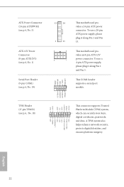
... an 8-pin ATX 12V power connector. TPM Header (17-pin TPMS1) (see p.6, No. 19) 12 24 1 13 8 5 4 1 his motherboard provides a 24-pin ATX power connector. To use a 20-pin ATX power supply, please plug it along Pin 1 and Pin 13. his COM1 header supports a ...
... an 8-pin ATX 12V power connector. TPM Header (17-pin TPMS1) (see p.6, No. 19) 12 24 1 13 8 5 4 1 his motherboard provides a 24-pin ATX power connector. To use a 20-pin ATX power supply, please plug it along Pin 1 and Pin 13. his COM1 header supports a ...
User Manual
Page 29
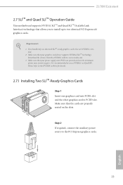
... on the slots. Make sure that allows you to install up to use identical SLITM-ready graphics cards that your system requires. Z170M Extreme4 2.7 SLITM and Quad SLITM Operation Guide his motherboard supports NVIDIA® SLITM and Quad SLITM (Scalable Link Interface) technology that your power supply unit (PSU) can provide at least...
... on the slots. Make sure that allows you to install up to use identical SLITM-ready graphics cards that your system requires. Z170M Extreme4 2.7 SLITM and Quad SLITM Operation Guide his motherboard supports NVIDIA® SLITM and Quad SLITM (Scalable Link Interface) technology that your power supply unit (PSU) can provide at least...
User Manual
Page 32
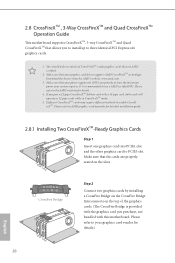
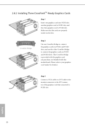
... graphics card driver supports AMD CrossFireXTM technology. 2.8 CrossFireXTM , 3-Way CrossFireXTM and Quad CrossFireXTM Operation Guide his motherboard supports CrossFireXTM, 3-way CrossFireXTM and Quad CrossFireXTM that allows you pair a 12-pipe CrossFireXTM Edition card with this motherboard. Download the drivers from the AMD's website: www.amd.com 3. If you to install up to...
... graphics card driver supports AMD CrossFireXTM technology. 2.8 CrossFireXTM , 3-Way CrossFireXTM and Quad CrossFireXTM Operation Guide his motherboard supports CrossFireXTM, 3-way CrossFireXTM and Quad CrossFireXTM that allows you pair a 12-pipe CrossFireXTM Edition card with this motherboard. Download the drivers from the AMD's website: www.amd.com 3. If you to install up to...
User Manual
Page 34
Make sure that is provided with the graphics card you purchase, not bundled with this motherboard. Please refer to your graphics card vendor for details.) Step 3 Connect a VGA cable or a DVI cable to the monitor connector or the DVI connector of ...
Make sure that is provided with the graphics card you purchase, not bundled with this motherboard. Please refer to your graphics card vendor for details.) Step 3 Connect a VGA cable or a DVI cable to the monitor connector or the DVI connector of ...
User Manual
Page 37
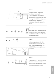
... default. Hand tighten the standof into the M.2 slot. English 31 Please do not overtighten the screw as this might damage the module. Z170M Extreme4 5 4 3 2 E D C B A E D C B A Step 3 Move the standof based on the motherboard. he standof is placed at the nut location C by hand. Skip Step 3 and 4 and go straight to Step 5 if you are...
... default. Hand tighten the standof into the M.2 slot. English 31 Please do not overtighten the screw as this might damage the module. Z170M Extreme4 5 4 3 2 E D C B A E D C B A Step 3 Move the standof based on the motherboard. he standof is placed at the nut location C by hand. Skip Step 3 and 4 and go straight to Step 5 if you are...
User Manual
Page 39
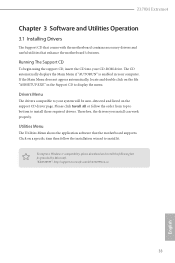
...microsot.com/kb/2720599/en-us 33 English Utilities Menu he Support CD that comes with the motherboard contains necessary drivers and useful utilities that the motherboard supports. he drivers compatible to install those required drivers. Click on the support CD driver page.... item then follow the order from top to bottom to your computer. Z170M Extreme4 Chapter 3 Software and Utilities Operation 3.1 Installing Drivers he Utilities Menu shows the application sotware that enhance the motherboard's features. To improve Windows 7 compatibility, please download and install the ...
...microsot.com/kb/2720599/en-us 33 English Utilities Menu he Support CD that comes with the motherboard contains necessary drivers and useful utilities that the motherboard supports. he drivers compatible to install those required drivers. Click on the support CD driver page.... item then follow the order from top to bottom to your computer. Z170M Extreme4 Chapter 3 Software and Utilities Operation 3.1 Installing Drivers he Utilities Menu shows the application sotware that enhance the motherboard's features. To improve Windows 7 compatibility, please download and install the ...
User Manual
Page 44
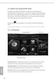
... and keep your motherboard up to date simply with a few clicks. on the image to perform job-related tasks. 3.3 ASRock Live Update & APP Shop he ASRock Live Update & APP Shop is an online store for purchasing and downloading sotware applications for your desktop to access ASRock Live Update & APP... Category Panel: he category panel contains several category tabs or buttons that when selected the information panel below displays the relative information. With ASRock APP Shop, you can quickly and easily install various apps and support utilities, such as USB Key, XFast LAN, XFast RAM and ...
... and keep your motherboard up to date simply with a few clicks. on the image to perform job-related tasks. 3.3 ASRock Live Update & APP Shop he ASRock Live Update & APP Shop is an online store for purchasing and downloading sotware applications for your desktop to access ASRock Live Update & APP... Category Panel: he category panel contains several category tabs or buttons that when selected the information panel below displays the relative information. With ASRock APP Shop, you can quickly and easily install various apps and support utilities, such as USB Key, XFast LAN, XFast RAM and ...
User Manual
Page 50
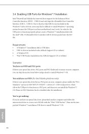
...kept the eXtensible Host Controller Interface (XHCI - Due to that fact that XHCI is not included in the ASRock Support CD or website) Scenarios You have an ODD and PS/2 ports: If there is an optical ...disabled ater the installation. Requirements • A Windows® 7 installation disk or USB drive • USB 3.0 drivers (included in the ASRock Support CD or website) • A Windows® PC • Win7 USB Patcher (included in the Windows 7 inbox drivers, users may... for the USB ports to install Windows 7 operating system because the USB ports on their motherboard won't work.
...kept the eXtensible Host Controller Interface (XHCI - Due to that fact that XHCI is not included in the ASRock Support CD or website) Scenarios You have an ODD and PS/2 ports: If there is an optical ...disabled ater the installation. Requirements • A Windows® 7 installation disk or USB drive • USB 3.0 drivers (included in the ASRock Support CD or website) • A Windows® PC • Win7 USB Patcher (included in the Windows 7 inbox drivers, users may... for the USB ports to install Windows 7 operating system because the USB ports on their motherboard won't work.
User Manual
Page 58
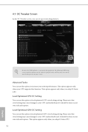
... is constantly being updated, the following UEFI setup screens and descriptions are for reference purpose only, and they may cause damage to your CPU and motherboard. Please note that overclocking may cause damage to your GPU and...
... is constantly being updated, the following UEFI setup screens and descriptions are for reference purpose only, and they may cause damage to your CPU and motherboard. Please note that overclocking may cause damage to your GPU and...

