
User Manual
Page 4
...1.2 Speciications 2 1.3 Motherboard Layout 6 1.4 I/O Panel 8 Chapter 2 Installation 10 2.1 Installing the CPU 11 2.2 Installing the CPU Fan and Heatsink 14 2.3 Installing Memory Modules (DIMM) 15 2.4 Expansion Slots (PCI Express Slots) 17 2.5 Jumpers Setup 18 2.6 Onboard Headers and Connectors 19 2.7 CrossFireXTM and Quad CrossFireXTM Operation Guide 23 2.7.2 Driver Installation and Setup 25 2.8 M.2_SSD (NGFF) Module Installation Guide 26 Chapter 3 Software and Utilities Operation 29 3.1 Installing Drivers 29 3.2 A-Tuning 30 3.3 ASRock Live Update & APP Shop 34...
...1.2 Speciications 2 1.3 Motherboard Layout 6 1.4 I/O Panel 8 Chapter 2 Installation 10 2.1 Installing the CPU 11 2.2 Installing the CPU Fan and Heatsink 14 2.3 Installing Memory Modules (DIMM) 15 2.4 Expansion Slots (PCI Express Slots) 17 2.5 Jumpers Setup 18 2.6 Onboard Headers and Connectors 19 2.7 CrossFireXTM and Quad CrossFireXTM Operation Guide 23 2.7.2 Driver Installation and Setup 25 2.8 M.2_SSD (NGFF) Module Installation Guide 26 Chapter 3 Software and Utilities Operation 29 3.1 Installing Drivers 29 3.2 A-Tuning 30 3.3 ASRock Live Update & APP Shop 34...
User Manual
Page 5
... BIOS & Drivers 38 3.3.4 Setting 39 3.4 Enabling USB Ports for Windows® 7 Installation 40 Chapter 4 UEFI SETUP UTILITY 43 4.1 Introduction 43 4.1.1 UEFI Menu Bar 43 4.1.2 Navigation Keys 44 4.2 Main Screen 45 4.3 OC Tweaker Screen 46 4.4 Advanced Screen 54 4.4.1 CPU Coniguration 55 4.4.2 Chipset Coniguration 57 4.4.3 Storage Coniguration 59 4.4.4 Super IO Coniguration 60 4.4.5 ACPI Coniguration 61 4.4.6 USB Coniguration 63 4.4.7 Trusted Computing 64 4.5 Tools 65 4.6 Hardware Health Event Monitoring Screen 69 4.7 Security Screen 71 4.8 Boot Screen...
... BIOS & Drivers 38 3.3.4 Setting 39 3.4 Enabling USB Ports for Windows® 7 Installation 40 Chapter 4 UEFI SETUP UTILITY 43 4.1 Introduction 43 4.1.1 UEFI Menu Bar 43 4.1.2 Navigation Keys 44 4.2 Main Screen 45 4.3 OC Tweaker Screen 46 4.4 Advanced Screen 54 4.4.1 CPU Coniguration 55 4.4.2 Chipset Coniguration 57 4.4.3 Storage Coniguration 59 4.4.4 Super IO Coniguration 60 4.4.5 ACPI Coniguration 61 4.4.6 USB Coniguration 63 4.4.7 Trusted Computing 64 4.5 Tools 65 4.6 Hardware Health Event Monitoring Screen 69 4.7 Security Screen 71 4.8 Boot Screen...
User Manual
Page 6
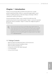
...; ASRock Z170M Pro4S Motherboard (Micro ATX Form Factor) • ASRock Z170M Pro4S Quick Installation Guide • ASRock Z170M Pro4S Support CD • 2 x Serial ATA (SATA) Data Cables (Optional) • 1 x I/O Panel Shield • 1 x Screw for speciic information about the model you for purchasing ASRock Z170M Pro4S motherboard, a reliable motherboard produced under ASRock's consistently stringent quality control. You may ind the latest VGA cards and CPU support list on ASRock's website without notice. Z170M Pro4S Chapter 1 Introduction hank you are using. In case any...
...; ASRock Z170M Pro4S Motherboard (Micro ATX Form Factor) • ASRock Z170M Pro4S Quick Installation Guide • ASRock Z170M Pro4S Support CD • 2 x Serial ATA (SATA) Data Cables (Optional) • 1 x I/O Panel Shield • 1 x Screw for speciic information about the model you for purchasing ASRock Z170M Pro4S motherboard, a reliable motherboard produced under ASRock's consistently stringent quality control. You may ind the latest VGA cards and CPU support list on ASRock's website without notice. Z170M Pro4S Chapter 1 Introduction hank you are using. In case any...
User Manual
Page 7
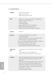
...-range Overclocking Chipset • Intel® Z170 Memory • Dual Channel DDR4 Memory Technology • 4 x DDR4 DIMM Slots • Supports DDR4 3200+(OC)*/2933(OC)/2800(OC)/2400 (OC)/2133 non-ECC, un-bufered memory * Please refer to Memory Support List on ASRock's website for more information. (http://www.asrock.com/) • Max. shared memory 1792MB English 2 PCIE4: x4 mode) • 2 x PCI Express 3.0 x1 Slots (Flexible PCIe) • Supports AMD Quad CrossFireXTM and CrossFireXTM Graphics •...
...-range Overclocking Chipset • Intel® Z170 Memory • Dual Channel DDR4 Memory Technology • 4 x DDR4 DIMM Slots • Supports DDR4 3200+(OC)*/2933(OC)/2800(OC)/2400 (OC)/2133 non-ECC, un-bufered memory * Please refer to Memory Support List on ASRock's website for more information. (http://www.asrock.com/) • Max. shared memory 1792MB English 2 PCIE4: x4 mode) • 2 x PCI Express 3.0 x1 Slots (Flexible PCIe) • Supports AMD Quad CrossFireXTM and CrossFireXTM Graphics •...
User Manual
Page 9
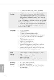
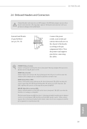
...SATA-type M.2 device, SATA3_0 and SATA3_1 will be disabled. • 1 x Ultra M.2 Socket, supports M.2 SATA3 6.0 Gb/s module and M.2 PCI Express module up to Gen3 x4 (32 Gb/s) * Supports ASRock U.2 Kit Connector • 1 x COM Port Header • 1 x TPM Header • 1 x Chassis Intrusion and Speaker Header • 1 x CPU Fan Connector (4-pin) (Smart Fan Speed Control) • 2 x Chassis Fan Connectors (4-pin) (Smart Fan Speed Control) • 1 x 24 pin ATX Power Connector • 1 x 8 pin 12V Power Connector • 1 x Front Panel Audio Connector • 1 x USB 2.0 Header (Supports...
...SATA-type M.2 device, SATA3_0 and SATA3_1 will be disabled. • 1 x Ultra M.2 Socket, supports M.2 SATA3 6.0 Gb/s module and M.2 PCI Express module up to Gen3 x4 (32 Gb/s) * Supports ASRock U.2 Kit Connector • 1 x COM Port Header • 1 x TPM Header • 1 x Chassis Intrusion and Speaker Header • 1 x CPU Fan Connector (4-pin) (Smart Fan Speed Control) • 2 x Chassis Fan Connectors (4-pin) (Smart Fan Speed Control) • 1 x 24 pin ATX Power Connector • 1 x 8 pin 12V Power Connector • 1 x Front Panel Audio Connector • 1 x USB 2.0 Header (Supports...
User Manual
Page 10
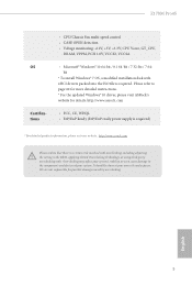
...; CPU/Chassis Fan multi-speed control • CASE OPEN detection • Voltage monitoring: +12V, +5V, +3.3V, CPU Vcore, GT_CPU, DRAM, VPPM, PCH 1.0V, VCCIO, VCCSA • Microsot® Windows® 10 64-bit / 8.1 64-bit / 7 32-bit / 7 64bit * To install Windows® 7 OS, a modiied installation disk with xHCI drivers packed into the ISO ile is a certain risk involved with overclocking, including adjusting the setting in the BIOS, applying Untied Overclocking Technology, or using third-party overclocking...
...; CPU/Chassis Fan multi-speed control • CASE OPEN detection • Voltage monitoring: +12V, +5V, +3.3V, CPU Vcore, GT_CPU, DRAM, VPPM, PCH 1.0V, VCCIO, VCCSA • Microsot® Windows® 10 64-bit / 8.1 64-bit / 7 32-bit / 7 64bit * To install Windows® 7 OS, a modiied installation disk with xHCI drivers packed into the ISO ile is a certain risk involved with overclocking, including adjusting the setting in the BIOS, applying Untied Overclocking Technology, or using third-party overclocking...
User Manual
Page 22
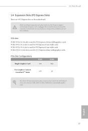
... power supply is switched of or the power cord is unplugged. Before installing an expansion card, please make necessary hardware settings for the card before you start the installation. PCIe Slot Conigurations Single Graphics Card PCIE1 x16 PCIE4 N/A Two Graphics Cards in CrossFireXTM Mode x16 x4 For a better thermal environment, please connect a chassis fan to the motherboard's chassis fan connector (CHA_FAN1 or CHA_FAN2) when using multiple graphics cards. PCIE2 (PCIe 3.0 x1 slot) is used for PCI Express x16 lane width graphics cards. PCIe slots: PCIE1 (PCIe 3.0 x16 slot...
... power supply is switched of or the power cord is unplugged. Before installing an expansion card, please make necessary hardware settings for the card before you start the installation. PCIe Slot Conigurations Single Graphics Card PCIE1 x16 PCIE4 N/A Two Graphics Cards in CrossFireXTM Mode x16 x4 For a better thermal environment, please connect a chassis fan to the motherboard's chassis fan connector (CHA_FAN1 or CHA_FAN2) when using multiple graphics cards. PCIE2 (PCIe 3.0 x1 slot) is used for PCI Express x16 lane width graphics cards. PCIe slots: PCIE1 (PCIe 3.0 x16 slot...
User Manual
Page 23
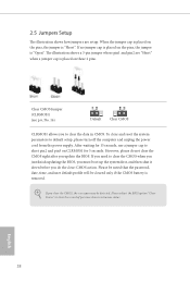
... the clear-CMOS action. If you update the BIOS. Please adjust the BIOS option "Clear Status" to default setup, please turn of previous chassis intrusion status. 2.5 Jumpers Setup he illustration shows a 3-pin jumper whose pin1 and pin2 are setup. To clear and reset the system parameters to clear the record of the computer and unplug the power cord from the power supply. When the jumper cap is "Short". he illustration shows how jumpers are "Short" when a jumper...
... the clear-CMOS action. If you update the BIOS. Please adjust the BIOS option "Clear Status" to default setup, please turn of previous chassis intrusion status. 2.5 Jumpers Setup he illustration shows a 3-pin jumper whose pin1 and pin2 are setup. To clear and reset the system parameters to clear the record of the computer and unplug the power cord from the power supply. When the jumper cap is "Short". he illustration shows how jumpers are "Short" when a jumper...
User Manual
Page 24
... the way to turn of (S5). Note the positive and negative pins before connecting the cables. You may difer by chassis. he LED is of power switch, reset switch, power LED, hard drive activity LED, speaker and etc. PLED (System Power LED): Connect to the motherboard. Placing jumper caps over these headers and connectors. PWRBTN (Power Switch): Connect to this header according to the reset switch on when the system is reading or writing data. When connecting your system using the power switch.
... the way to turn of (S5). Note the positive and negative pins before connecting the cables. You may difer by chassis. he LED is of power switch, reset switch, power LED, hard drive activity LED, speaker and etc. PLED (System Power LED): Connect to the motherboard. Placing jumper caps over these headers and connectors. PWRBTN (Power Switch): Connect to this header according to the reset switch on when the system is reading or writing data. When connecting your system using the power switch.
User Manual
Page 26
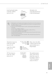
... the instructions in the Realtek Control panel and adjust "Recording Volume". B. Connect Audio_R (RIN) to OUT2_R and Audio_L (LIN) to function correctly. Chassis Fan Connectors (4-pin CHA_FAN1) (see p.6, No. 21) (4-pin CHA_FAN2) (see p.6, No. 9) CPU Fan Connector (4-pin CPU_FAN1) (see p.6, No. 20) GND PRESENCE# MIC_RET OUT_RET 1 OUT2_L J_SENSE OUT2_R MIC2_R MIC2_L his motherboard provides a 4-Pin CPU fan (Quiet Fan) connector. High Deinition Audio supports Jack Sensing, but the panel wire on the chassis must support HDA...
... the instructions in the Realtek Control panel and adjust "Recording Volume". B. Connect Audio_R (RIN) to OUT2_R and Audio_L (LIN) to function correctly. Chassis Fan Connectors (4-pin CHA_FAN1) (see p.6, No. 21) (4-pin CHA_FAN2) (see p.6, No. 9) CPU Fan Connector (4-pin CPU_FAN1) (see p.6, No. 20) GND PRESENCE# MIC_RET OUT_RET 1 OUT2_L J_SENSE OUT2_R MIC2_R MIC2_L his motherboard provides a 4-Pin CPU fan (Quiet Fan) connector. High Deinition Audio supports Jack Sensing, but the panel wire on the chassis must support HDA...
User Manual
Page 28
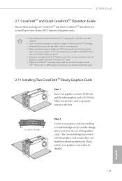
... Interconnects on the slots. Z170M Pro4S 2.7 CrossFireXTM and Quad CrossFireXTM Operation Guide his motherboard supports CrossFireXTM and Quad CrossFireXTM that allows you to install up to enable CrossFireXTM. Make sure that your power supply unit (PSU) can provide at least the minimum power your graphics card driver supports AMD CrossFireXTM technology. You should only use a AMD certiied PSU. Diferent CrossFireXTM cards may require diferent methods to three identical PCI Express x16 graphics cards. 1.
... Interconnects on the slots. Z170M Pro4S 2.7 CrossFireXTM and Quad CrossFireXTM Operation Guide his motherboard supports CrossFireXTM and Quad CrossFireXTM that allows you to install up to enable CrossFireXTM. Make sure that your power supply unit (PSU) can provide at least the minimum power your graphics card driver supports AMD CrossFireXTM technology. You should only use a AMD certiied PSU. Diferent CrossFireXTM cards may require diferent methods to three identical PCI Express x16 graphics cards. 1.
User Manual
Page 34
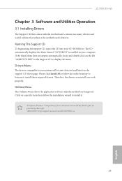
... the installation wizard to display the menu. Utilities Menu he Utilities Menu shows the application sotware that enhance the motherboard's features. Click on the support CD driver page. Z170M Pro4S Chapter 3 Software and Utilities Operation 3.1 Installing Drivers he Support CD that comes with the motherboard contains necessary drivers and useful utilities that the motherboard supports. he CD automatically displays the Main Menu if "AUTORUN" is enabled in the Support CD to install it. herefore, the drivers you install can work properly...
... the installation wizard to display the menu. Utilities Menu he Utilities Menu shows the application sotware that enhance the motherboard's features. Click on the support CD driver page. Z170M Pro4S Chapter 3 Software and Utilities Operation 3.1 Installing Drivers he Support CD that comes with the motherboard contains necessary drivers and useful utilities that the motherboard supports. he CD automatically displays the Main Menu if "AUTORUN" is enabled in the Support CD to install it. herefore, the drivers you install can work properly...
User Manual
Page 45
..., please enable the "PS/2 Simulator" option in UEFI SETUP UTILITY > Advanced > USB Coniguration, which allows the USB port to function as a PS/2 port, and then you can skip the instructions below to function properly, please create a Windows® 7 installation disk with the "Win7 USB Patcher". hen use the new patched Windows® 7 installation USB drive to disabled ater the installation. In order for the Enhanced Host Controller Interface (EHCI - Please set PS/S Simulator...
..., please enable the "PS/2 Simulator" option in UEFI SETUP UTILITY > Advanced > USB Coniguration, which allows the USB port to function as a PS/2 port, and then you can skip the instructions below to function properly, please create a Windows® 7 installation disk with the "Win7 USB Patcher". hen use the new patched Windows® 7 installation USB drive to disabled ater the installation. In order for the Enhanced Host Controller Interface (EHCI - Please set PS/S Simulator...
User Manual
Page 46
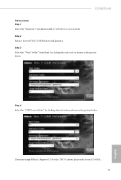
Step 3 Select the "Win7 Folder" from Step1 by clicking the red circle as shown as the picture below . If you are using ASRock's Support CD for the USB 3.0 driver, please select your system. Step 2 Extract the tool (Win7 USB Patcher) and launch it. Step 4 Select the "USB Driver Folder" by clicking the red circle as shown as the picture below . Z170M Pro4S Instructions Step 1 Insert the Windows® 7 installation disk or USB drive to your CD-ROM. 41 English
Step 3 Select the "Win7 Folder" from Step1 by clicking the red circle as shown as the picture below . If you are using ASRock's Support CD for the USB 3.0 driver, please select your system. Step 2 Extract the tool (Win7 USB Patcher) and launch it. Step 4 Select the "USB Driver Folder" by clicking the red circle as shown as the picture below . Z170M Pro4S Instructions Step 1 Insert the Windows® 7 installation disk or USB drive to your CD-ROM. 41 English
User Manual
Page 63
... graphics when an external graphics card is on AC/Power Loss Select the power state ater a power failure. Inte(R) Ethernet Connection I219-V Enable or disable the onboard network interface controller (Intel® I219V). Good Night LED By enabling Good Night LED, the Power/HDD LEDs will start to enable onboard HD audio and automatically disable it when a sound card is idle for all times. Front Panel Enable/disable front panel HD audio. If [Power Of] is selected, the power will also automatically switch of memory...
... graphics when an external graphics card is on AC/Power Loss Select the power state ater a power failure. Inte(R) Ethernet Connection I219-V Enable or disable the onboard network interface controller (Intel® I219V). Good Night LED By enabling Good Night LED, the Power/HDD LEDs will start to enable onboard HD audio and automatically disable it when a sound card is idle for all times. Front Panel Enable/disable front panel HD audio. If [Power Of] is selected, the power will also automatically switch of memory...
User Manual
Page 65
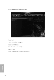
PS2 Y-Cable Enable the PS2 Y-Cable or set this option to Auto. 60 English 4.4.4 Super IO Coniguration Serial Port Enable or disable the Serial port. Serial Port Address Select the address of the Serial port.
PS2 Y-Cable Enable the PS2 Y-Cable or set this option to Auto. 60 English 4.4.4 Super IO Coniguration Serial Port Enable or disable the Serial port. Serial Port Address Select the address of the Serial port.
User Manual
Page 70
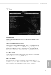
... can start installing the operating system in RAID mode. 65 English You may schedule the starting and ending hours of your current PC and the devices connected. Please setup network coniguration before using UEFI Tech Service. UEFI Tech Service Contact ASRock Tech Service if you are able to establish an internet curfew or restrict internet access at speciied times via OMG. Ater copying the drivers please change the SATA mode to RAID...
... can start installing the operating system in RAID mode. 65 English You may schedule the starting and ending hours of your current PC and the devices connected. Please setup network coniguration before using UEFI Tech Service. UEFI Tech Service Contact ASRock Tech Service if you are able to establish an internet curfew or restrict internet access at speciied times via OMG. Ater copying the drivers please change the SATA mode to RAID...
User Manual
Page 71
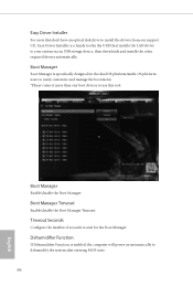
... easily customize and manage the boot menu. *Please connect more than one boot devices to use this tool. Boot Manager Enable/disable the Boot Manager. Easy Driver Installer For users that don't have an optical disk drive to install the drivers from our support CD, Easy Driver Installer is enabled, the computer will power on automatically to dehumidify the system ater entering S4/S5 state. 66 English Boot Manager Boot Manager is speciically designed for...
... easily customize and manage the boot menu. *Please connect more than one boot devices to use this tool. Boot Manager Enable/disable the Boot Manager. Easy Driver Installer For users that don't have an optical disk drive to install the drivers from our support CD, Easy Driver Installer is enabled, the computer will power on automatically to dehumidify the system ater entering S4/S5 state. 66 English Boot Manager Boot Manager is speciically designed for...

User Manual
Page 73
Network Coniguration Use this to download the UEFI irmware. 68 English UEFI Download Server Select a server to conigure internet connection settings for Internet Flash. Internet Setting Enable or disable sound efects in the setup utility.
Network Coniguration Use this to download the UEFI irmware. 68 English UEFI Download Server Select a server to conigure internet connection settings for Internet Flash. Internet Setting Enable or disable sound efects in the setup utility.
User Manual
Page 76
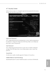
... blank and press enter to enable or disable support for the user account. Intel(R) Platform Trust Technology Enable/disable Intel PTT in the UEFI Setup Utility. Disable this item to remove the password. Users are unable to change the settings in the UEFI Setup Utility. Z170M Pro4S 4.7 Security Screen In this section you may also clear the user password. You may set or change the supervisor/user password for the administrator account. Supervisor Password Set or change the password for Windows 8.1 Secure Boot. Only the...
... blank and press enter to enable or disable support for the user account. Intel(R) Platform Trust Technology Enable/disable Intel PTT in the UEFI Setup Utility. Disable this item to remove the password. Users are unable to change the settings in the UEFI Setup Utility. Z170M Pro4S 4.7 Security Screen In this section you may also clear the user password. You may set or change the supervisor/user password for the administrator account. Supervisor Password Set or change the password for Windows 8.1 Secure Boot. Only the...


