
User Manual
Page 5
... Guide 42 Chapter 3 Software and Utilities Operation 45 3.1 Installing Drivers 45 3.2 Formula Drive 46 3.3 ASRock Live Update & APP Shop 50 3.3.1 UI Overview 50 3.3.2 Apps 51 3.3.3 BIOS & Drivers 54 3.3.4 Setting 55 3.4 Enabling USB Ports for Windows® 7... Installation 56 Chapter 4 UEFI SETUP UTILITY 59 4.1 Introduction 59 4.1.1 UEFI Menu Bar 59 4.1.2 Navigation Keys 60 4.2 Main Screen 61 4.3 OC...
... Guide 42 Chapter 3 Software and Utilities Operation 45 3.1 Installing Drivers 45 3.2 Formula Drive 46 3.3 ASRock Live Update & APP Shop 50 3.3.1 UI Overview 50 3.3.2 Apps 51 3.3.3 BIOS & Drivers 54 3.3.4 Setting 55 3.4 Enabling USB Ports for Windows® 7... Installation 56 Chapter 4 UEFI SETUP UTILITY 59 4.1 Introduction 59 4.1.1 UEFI Menu Bar 59 4.1.2 Navigation Keys 60 4.2 Main Screen 61 4.3 OC...
User Manual
Page 7
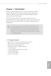
Chapter 3 contains the operation guide of the BIOS setup. You may ind the latest VGA cards and CPU support list on ASRock's website without notice. ASRock website http://www.asrock.com. 1.1 Package Contents • ASRock Z170 OC Formula Motherboard (ATX Form Factor) • ASRock Z170 OC Formula Quick Installation Guide • ASRock Z170 OC Formula Support CD • 4 x Serial ATA (SATA) Data Cables (Optional) • 1 x I/O Panel Shield...
Chapter 3 contains the operation guide of the BIOS setup. You may ind the latest VGA cards and CPU support list on ASRock's website without notice. ASRock website http://www.asrock.com. 1.1 Package Contents • ASRock Z170 OC Formula Motherboard (ATX Form Factor) • ASRock Z170 OC Formula Quick Installation Guide • ASRock Z170 OC Formula Support CD • 4 x Serial ATA (SATA) Data Cables (Optional) • 1 x I/O Panel Shield...
User Manual
Page 11
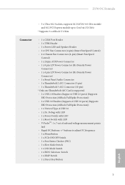
...; 2 x USB 3.0 Headers (Supports 4 USB 3.0 ports) (Supports ESD Protection (ASRock Full Spike Protection)) • 1 x Vertical Type A USB 3.0 • 1 x Dr. Debug with LED • 1 x Power Switch with LED • 1 x Reset Switch with LED • V-ProbeTM: 1 x 7-set of onboard voltage measurement points laid • Rapid OC Buttons: +/- Z170 OC Formula • 3 x Ultra M.2 Sockets, supports M.2 SATA3 6.0 Gb/s module and...
...; 2 x USB 3.0 Headers (Supports 4 USB 3.0 ports) (Supports ESD Protection (ASRock Full Spike Protection)) • 1 x Vertical Type A USB 3.0 • 1 x Dr. Debug with LED • 1 x Power Switch with LED • 1 x Reset Switch with LED • V-ProbeTM: 1 x 7-set of onboard voltage measurement points laid • Rapid OC Buttons: +/- Z170 OC Formula • 3 x Ultra M.2 Sockets, supports M.2 SATA3 6.0 Gb/s module and...
User Manual
Page 12
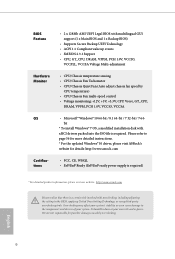
...'s stability, or even cause damage to page 56 for more detailed instructions. * For the updated Windows® 10 driver, please visit ASRock's website for possible damage caused by CPU temperature) • CPU/Chassis Fan multi-speed control • Voltage monitoring: +12V, +5V..., or using third-party overclocking tools. It should be done at your system. BIOS Feature Hardware Monitor OS Certiications • 2 x 128Mb AMI UEFI Legal BIOS with multilingual GUI support (1 x Main BIOS and 1 x Backup BIOS) • Supports Secure Backup UEFI Technology • ACPI 1.1 Compliant wake up...
...'s stability, or even cause damage to page 56 for more detailed instructions. * For the updated Windows® 10 driver, please visit ASRock's website for possible damage caused by CPU temperature) • CPU/Chassis Fan multi-speed control • Voltage monitoring: +12V, +5V..., or using third-party overclocking tools. It should be done at your system. BIOS Feature Hardware Monitor OS Certiications • 2 x 128Mb AMI UEFI Legal BIOS with multilingual GUI support (1 x Main BIOS and 1 x Backup BIOS) • Supports Secure Backup UEFI Technology • ACPI 1.1 Compliant wake up...
User Manual
Page 13
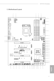
Z170 OC Formula 1.3 Motherboard Layout 1 2 3 4 5 USB 2.0 T: USB1 B: USB2 PS2 Keyboard /Mouse Clr CMOS ATX12V1 ATX12V2 VOL_CON1 6 CPU_FAN2 CHA_FAN4 7 CPU DRAM VGA BOOT 8 DISPLAY1 HDMI1 DDR4_A1 (64 bit, 288-... 16 SATA3_3 SATA3_1 CT5 CT4 CT3 CT2 CT1 17 Z170 OC Formula 18 SATA_EXP1 SATA_EXP0 PCIE2 19 20 Intel SATA3_A3 SATA3_A4 21 M2_2 PCIE3 CT4 CT3 CT2 CT1 Ultra M.2 Z170 22 23 SATA3_A2 SATA3_A1 PCIe Gen3 x4 Purity SoundTM 3 PCIE4 BIOS_B_LED BIOS_A_LED BIOS_B1 128Mb BIOS BIOS_A1 128Mb BIOS 24 25 26 M2_3 PCIE5 CT4 CT3 CT2...
Z170 OC Formula 1.3 Motherboard Layout 1 2 3 4 5 USB 2.0 T: USB1 B: USB2 PS2 Keyboard /Mouse Clr CMOS ATX12V1 ATX12V2 VOL_CON1 6 CPU_FAN2 CHA_FAN4 7 CPU DRAM VGA BOOT 8 DISPLAY1 HDMI1 DDR4_A1 (64 bit, 288-... 16 SATA3_3 SATA3_1 CT5 CT4 CT3 CT2 CT1 17 Z170 OC Formula 18 SATA_EXP1 SATA_EXP0 PCIE2 19 20 Intel SATA3_A3 SATA3_A4 21 M2_2 PCIE3 CT4 CT3 CT2 CT1 Ultra M.2 Z170 22 23 SATA3_A2 SATA3_A1 PCIe Gen3 x4 Purity SoundTM 3 PCIE4 BIOS_B_LED BIOS_A_LED BIOS_B1 128Mb BIOS BIOS_A1 128Mb BIOS 24 25 26 M2_3 PCIE5 CT4 CT3 CT2...
User Manual
Page 14
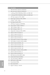
... SATA3 Connector (SATA3_A4) 22 SATA3 Connector (SATA3_A1) 23 SATA3 Connector (SATA3_A2) 24 SATA Express Connector (SATA_EXP2) 25 SATA3 Connector (SATA3_5) 26 SATA3 Connector (SATA3_4) 27 BIOS Selection Switch (BIOS_SEL1) 28 System Panel Header (PANEL1) 29 Direct Key Button (DIRKEY1) 30 XMP Switch (XMP_ON1) 31 Power Switch (PWR) 32 Reset Switch (RST...
... SATA3 Connector (SATA3_A4) 22 SATA3 Connector (SATA3_A1) 23 SATA3 Connector (SATA3_A2) 24 SATA Express Connector (SATA_EXP2) 25 SATA3 Connector (SATA3_5) 26 SATA3 Connector (SATA3_4) 27 BIOS Selection Switch (BIOS_SEL1) 28 System Panel Header (PANEL1) 29 Direct Key Button (DIRKEY1) 30 XMP Switch (XMP_ON1) 31 Power Switch (PWR) 32 Reset Switch (RST...
User Manual
Page 27
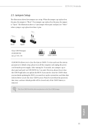
When the jumper cap is placed on the pins, the jumper is removed. If you need to short pin2 and pin3 on these 2 pins. Z170 OC Formula 2.5 Jumpers Setup he Clear CMOS Switch has the same function as the Clear CMOS jumper. To clear and reset the system parameters to clear the ... jumper whose pin1 and pin2 are setup. Ater waiting for 15 seconds, use a jumper cap to clear the CMOS when you just inish updating the BIOS, you must boot up the system irst, and then shut it down before you update the...
When the jumper cap is placed on the pins, the jumper is removed. If you need to short pin2 and pin3 on these 2 pins. Z170 OC Formula 2.5 Jumpers Setup he Clear CMOS Switch has the same function as the Clear CMOS jumper. To clear and reset the system parameters to clear the ... jumper whose pin1 and pin2 are setup. Ater waiting for 15 seconds, use a jumper cap to clear the CMOS when you just inish updating the BIOS, you must boot up the system irst, and then shut it down before you update the...
User Manual
Page 34
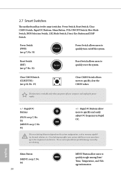
... Date/ Time, Temperature, and Voltage information. Reset Switch (RST) (see p.7, No. 31) Power Power Switch allows users to quickly and easily adjust OC frequency in Rapid OC. Clear CMOS Switch (CLRCBTN1) (see p.10, No. 15) Clear CMOS Switch allows users to the components and devices. Rapid... you power of the system. English 2.7 Smart Switches he motherboard has twelve smart switches: Power Switch, Reset Switch, Clear CMOS Switch, Rapid OC Buttons, Menu Button, PCIe ON/OFF Switch, Slow Mode Switch, BIOS Selection Switch, LN2 Mode Switch, Direct Key Button and XMP Switch.
... Date/ Time, Temperature, and Voltage information. Reset Switch (RST) (see p.7, No. 31) Power Power Switch allows users to quickly and easily adjust OC frequency in Rapid OC. Clear CMOS Switch (CLRCBTN1) (see p.10, No. 15) Clear CMOS Switch allows users to the components and devices. Rapid... you power of the system. English 2.7 Smart Switches he motherboard has twelve smart switches: Power Switch, Reset Switch, Clear CMOS Switch, Rapid OC Buttons, Menu Button, PCIe ON/OFF Switch, Slow Mode Switch, BIOS Selection Switch, LN2 Mode Switch, Direct Key Button and XMP Switch.
User Manual
Page 35
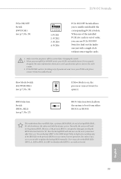
... Switch (SLOWMODE1) (see p.7, No. 34) ON If Slow Mode is for debug only. his motherboard has two BIOS chips, a primary BIOS (BIOS_A) and a backup BIOS (BIOS_ B), which BIOS is out of order, you can use PCIe ON/OFF Switch to use "Secure Backup UEFI" in the UEFI Setup... PCIE x16 cards is currently activated. PCIe ON/OFF switch is on the primary BIOS. BIOS Selection Switch (BIOS_SEL1) (see p.7, No. 27) AB BIOS Selection Switch allows the system to enable and disable the corresponding PCIE x16 slots. Z170 OC Formula PCIe ON/OFF Switch (SWITCH1) (see p.7, No. 39) ON 1234 1: ...
... Switch (SLOWMODE1) (see p.7, No. 34) ON If Slow Mode is for debug only. his motherboard has two BIOS chips, a primary BIOS (BIOS_A) and a backup BIOS (BIOS_ B), which BIOS is out of order, you can use PCIe ON/OFF Switch to use "Secure Backup UEFI" in the UEFI Setup... PCIE x16 cards is currently activated. PCIe ON/OFF switch is on the primary BIOS. BIOS Selection Switch (BIOS_SEL1) (see p.7, No. 27) AB BIOS Selection Switch allows the system to enable and disable the corresponding PCIE x16 slots. Z170 OC Formula PCIe ON/OFF Switch (SWITCH1) (see p.7, No. 39) ON 1234 1: ...
User Manual
Page 60
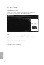
Click to select one or more details. Click on Step 2 to see a list of recommended or critical updates for the BIOS or drivers. Please update them all soon. Step 1 Please check the item information before update. Step 3 Click Update to update. 3.3.3 BIOS & Drivers Installing BIOS or Drivers When the "BIOS & Drivers" tab is selected, you will see more items you want to start the update process. 54 English
Click to select one or more details. Click on Step 2 to see a list of recommended or critical updates for the BIOS or drivers. Please update them all soon. Step 1 Please check the item information before update. Step 3 Click Update to update. 3.3.3 BIOS & Drivers Installing BIOS or Drivers When the "BIOS & Drivers" tab is selected, you will see more items you want to start the update process. 54 English
User Manual
Page 67
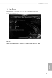
Favorite Display your collection of BIOS items. Press F5 to add/remove your favorite items. 61 English Z170 OC Formula 4.2 Main Screen When you enter the UEFI SETUP UTILITY, the Main screen will appear and display the system overview.
Favorite Display your collection of BIOS items. Press F5 to add/remove your favorite items. 61 English Z170 OC Formula 4.2 Main Screen When you enter the UEFI SETUP UTILITY, the Main screen will appear and display the system overview.
User Manual
Page 70
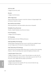
... Conigure the CPU PLL ORT. OC Tweaking Enable this option for better power saving and heat dissipation. A lower limit can protect the CPU and save power, while a higher limit may improve performance. Divider Conigure the BCLK divider. Boot Performance Mode Select the performance state that the BIOS will be lowered ater a period...
... Conigure the CPU PLL ORT. OC Tweaking Enable this option for better power saving and heat dissipation. A lower limit can protect the CPU and save power, while a higher limit may improve performance. Divider Conigure the BCLK divider. Boot Performance Mode Select the performance state that the BIOS will be lowered ater a period...
User Manual
Page 95
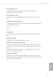
... is recommended to update your USB pen drive before using Internet Flash. *For BIOS backup and recovery purpose, it returns to the secondary lash ROM. 89 English Dehumidiier.... he higher the value, the faster the fan speed. DHCP (Auto IP), Auto ASRock Internet Flash downloads and updates the latest UEFI irmware version from our servers for you. Intel... in your UEFI. Please setup network coniguration before it is enabled. Internet Flash - Z170 OC Formula Dehumidiier Period Conigure the period of the dehumidifying process before using this function. Dehumidiier Duration...
... is recommended to update your USB pen drive before using Internet Flash. *For BIOS backup and recovery purpose, it returns to the secondary lash ROM. 89 English Dehumidiier.... he higher the value, the faster the fan speed. DHCP (Auto IP), Auto ASRock Internet Flash downloads and updates the latest UEFI irmware version from our servers for you. Intel... in your UEFI. Please setup network coniguration before it is enabled. Internet Flash - Z170 OC Formula Dehumidiier Period Conigure the period of the dehumidifying process before using this function. Dehumidiier Duration...


