

User Manual
Page 2
...this device must accept any errors or omissions that may apply, see www.dtsc.ca.gov/hazardouswaste/ perchlorate" ASRock Website: http://www.asrock.com All rights reserved. Products and corporate names appearing in Perchlorate Best Management Practices (BMP) regulations passed by... the purchaser for a particular purpose. Disclaimer: Speciications and information contained in this motherboard contains Perchlorate, a toxic substance ...
...this device must accept any errors or omissions that may apply, see www.dtsc.ca.gov/hazardouswaste/ perchlorate" ASRock Website: http://www.asrock.com All rights reserved. Products and corporate names appearing in Perchlorate Best Management Practices (BMP) regulations passed by... the purchaser for a particular purpose. Disclaimer: Speciications and information contained in this motherboard contains Perchlorate, a toxic substance ...
User Manual
Page 4
Contents Chapter 1 Introduction 1 1.1 Package Contents 1 1.2 Speciications 2 1.3 Motherboard Layout 7 1.4 I/O Panel 9 1.5 ASRock Front USB 3.1 Panel (for Z170 Extreme6+ only) 11 Chapter 2 Installation 14 2.1 Installing the CPU 15 2.2 Installing the CPU Fan and Heatsink 18 2.3 Installing Memory Modules (DIMM) 19 2.4 Expansion Slots (PCI Express ...
Contents Chapter 1 Introduction 1 1.1 Package Contents 1 1.2 Speciications 2 1.3 Motherboard Layout 7 1.4 I/O Panel 9 1.5 ASRock Front USB 3.1 Panel (for Z170 Extreme6+ only) 11 Chapter 2 Installation 14 2.1 Installing the CPU 15 2.2 Installing the CPU Fan and Heatsink 18 2.3 Installing Memory Modules (DIMM) 19 2.4 Expansion Slots (PCI Express ...

User Manual
Page 7
...; ASRock Z170 Extreme6+ / Z170 Extreme6 Quick Installation Guide • ASRock Z170 Extreme6+ / Z170 Extreme6 Support CD • 4 x Serial ATA (SATA) Data Cables (Optional) • 1 x I/O Panel Shield • 1 x ASRock SLI_Bridge_2S Card • 1 x Screw for M.2 Socket • 1 x ASRock Front USB 3.1 Panel (for Z170 Extreme6+ only) • 4 x Screws for Front USB 3.1 Panel (for Z170 Extreme6+ only) • 1 x SATA Express Cable (for Z170 Extreme6+ only) • 1 x USB Power Cable (for purchasing ASRock Z170 Extreme6+ / Z170 Extreme6 motherboard, a reliable motherboard...
...; ASRock Z170 Extreme6+ / Z170 Extreme6 Quick Installation Guide • ASRock Z170 Extreme6+ / Z170 Extreme6 Support CD • 4 x Serial ATA (SATA) Data Cables (Optional) • 1 x I/O Panel Shield • 1 x ASRock SLI_Bridge_2S Card • 1 x Screw for M.2 Socket • 1 x ASRock Front USB 3.1 Panel (for Z170 Extreme6+ only) • 4 x Screws for Front USB 3.1 Panel (for Z170 Extreme6+ only) • 1 x SATA Express Cable (for Z170 Extreme6+ only) • 1 x USB Power Cable (for purchasing ASRock Z170 Extreme6+ / Z170 Extreme6 motherboard, a reliable motherboard...
User Manual
Page 13
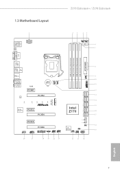
PS2 Keyboard /Mouse USB 3.0 T: USB5 B: USB6 1.3 Motherboard Layout 1 ATX12V1 CLRC BTN2 Z170 Extreme6+ / Z170 Extreme6 23 45 CHA_FAN1 CHA_FAN4 Power Reset 6 7 DVI1 HDMI1 DISPLAY1 DDR4_A1 (64 bit, 288-pin module) DDR4_A2 (64 bit, 288-pin ... 10 11 1 12 SATA3_A0_A1 PCIE2 13 LAN 14 SATA3_2_3 Ultra M.2 PCIe Gen3 x4 M2_1 SATA_EXP_0_1 SATA3_1_5 CT5 CT4 CT3 CT2 CT1 SATA3_0_4 15 Z170 Extreme6 Intel Purity SoundTM 3 PCIE3 Z170 16 PCIE4 17 PCIE5 HD_AUDIO1 1 COM1 1 PCIE6 TPMS1 1 1 T B1 USB1_2 1 USB3_4 1 BIOS_B1 BIOS_B_LED 128Mb BIOS BIOS_A_LED 128Mb BIOS BIOS_A1...
PS2 Keyboard /Mouse USB 3.0 T: USB5 B: USB6 1.3 Motherboard Layout 1 ATX12V1 CLRC BTN2 Z170 Extreme6+ / Z170 Extreme6 23 45 CHA_FAN1 CHA_FAN4 Power Reset 6 7 DVI1 HDMI1 DISPLAY1 DDR4_A1 (64 bit, 288-pin module) DDR4_A2 (64 bit, 288-pin ... 10 11 1 12 SATA3_A0_A1 PCIE2 13 LAN 14 SATA3_2_3 Ultra M.2 PCIe Gen3 x4 M2_1 SATA_EXP_0_1 SATA3_1_5 CT5 CT4 CT3 CT2 CT1 SATA3_0_4 15 Z170 Extreme6 Intel Purity SoundTM 3 PCIE3 Z170 16 PCIE4 17 PCIE5 HD_AUDIO1 1 COM1 1 PCIE6 TPMS1 1 1 T B1 USB1_2 1 USB3_4 1 BIOS_B1 BIOS_B_LED 128Mb BIOS BIOS_A_LED 128Mb BIOS BIOS_A1...

User Manual
Page 17
..., the device should support Type-C standards to install the ASRock Front USB 3.1 Panel into the drive bay of your motherboard. • 1 x USB 3.1 Type-C Port (10 Gb/s) (Supports ESD Protection (ASRock Full Spike Protection)) * his port supports power outputs up...(3 Amp) and Sleep state (1 Amp). * Some Type-C USB devices may only be charged by its own adapter. English 11 Z170 Extreme6+ / Z170 Extreme6 1.5 ASRock Front USB 3.1 Panel (for Z170 Extreme6+ only) Speciications Dimension • 75mm (W) x 42.8mm (H) x 148mm (L) Controller • ASMedia ASM1142 Controller Front Panel ...
..., the device should support Type-C standards to install the ASRock Front USB 3.1 Panel into the drive bay of your motherboard. • 1 x USB 3.1 Type-C Port (10 Gb/s) (Supports ESD Protection (ASRock Full Spike Protection)) * his port supports power outputs up...(3 Amp) and Sleep state (1 Amp). * Some Type-C USB devices may only be charged by its own adapter. English 11 Z170 Extreme6+ / Z170 Extreme6 1.5 ASRock Front USB 3.1 Panel (for Z170 Extreme6+ only) Speciications Dimension • 75mm (W) x 42.8mm (H) x 148mm (L) Controller • ASMedia ASM1142 Controller Front Panel ...

User Manual
Page 19
Step 7 Connect the other end of the SATA Express Cable to the USB 2.0 Header on the motherboard. SATA3_4_5 SATA3_A1_A2 SATA3_A3_A4 SATA_EXP0 SATA3_1_3 SATA3_0_2 Step 8 Connect the other end of the USB Power Cable to the SATA Express Connector on the motherboard. USB 3.0 USB 3.0 English Z170 Extreme6+ / Z170 Extreme6 Step 5 Screw ASRock Front USB 3.1 Panel to the SATA Power Connector. USB3_4 USB3_4 13 SATA3_4_5 SATA3_A1_A2 SATA3_A3_A4 SATA_EXP0 SATA3_1_3 SATA3_0_2 Step 6 Connect the PSU's SATA Power Cable to the drive bay with screws.
Step 7 Connect the other end of the SATA Express Cable to the USB 2.0 Header on the motherboard. SATA3_4_5 SATA3_A1_A2 SATA3_A3_A4 SATA_EXP0 SATA3_1_3 SATA3_0_2 Step 8 Connect the other end of the USB Power Cable to the SATA Express Connector on the motherboard. USB 3.0 USB 3.0 English Z170 Extreme6+ / Z170 Extreme6 Step 5 Screw ASRock Front USB 3.1 Panel to the SATA Power Connector. USB3_4 USB3_4 13 SATA3_4_5 SATA3_A1_A2 SATA3_A3_A4 SATA_EXP0 SATA3_1_3 SATA3_0_2 Step 6 Connect the PSU's SATA Power Cable to the drive bay with screws.

User Manual
Page 20
...you handle the components. • Hold components by the edges and do not touch the ICs. • Whenever you install motherboard components or change any motherboard settings. • Make sure to unplug the power cord before you uninstall any components, place them on a carpet. Chapter ...2 Installation his is an ATX form factor motherboard. Doing so may cause physical injuries and damages to motherboard components. • In order to avoid damage from static electricity to ensure that comes with the components. ...
...you handle the components. • Hold components by the edges and do not touch the ICs. • Whenever you install motherboard components or change any motherboard settings. • Make sure to unplug the power cord before you uninstall any components, place them on a carpet. Chapter ...2 Installation his is an ATX form factor motherboard. Doing so may cause physical injuries and damages to motherboard components. • In order to avoid damage from static electricity to ensure that comes with the components. ...

User Manual
Page 23
he cover must be placed if you wish to return the motherboard for ater service. 17 English Z170 Extreme6+ / Z170 Extreme6 Please save and replace the cover if the processor is removed.
he cover must be placed if you wish to return the motherboard for ater service. 17 English Z170 Extreme6+ / Z170 Extreme6 Please save and replace the cover if the processor is removed.

User Manual
Page 25
... slot; It is unable to install identical (the same brand, speed, size and chip-type) DDR4 DIMM pairs. 2. otherwise, this motherboard and DIMM may be damaged. Z170 Extreme6+ / Z170 Extreme6 2.3 Installing Memory Modules (DIMM) his motherboard provides four 288-pin DDR4 (Double Data Rate 4) DIMM slots, and supports Dual Channel Memory Technology. 1. It is not allowed...
... slot; It is unable to install identical (the same brand, speed, size and chip-type) DDR4 DIMM pairs. 2. otherwise, this motherboard and DIMM may be damaged. Z170 Extreme6+ / Z170 Extreme6 2.3 Installing Memory Modules (DIMM) his motherboard provides four 288-pin DDR4 (Double Data Rate 4) DIMM slots, and supports Dual Channel Memory Technology. 1. It is not allowed...

User Manual
Page 27
... a chassis fan to the motherboard's chassis fan connector (CHA_FAN1, CHA_FAN2, CHA_FAN3 or CHA_FAN4) when using multiple graphics cards. 21 Please read the documentation of or the power cord is used for the card before you start the installation. PCIE5 (PCIe 3.0 x1 slot) is unplugged. Z170 Extreme6+ / Z170 Extreme6 2.4 Expansion Slots (PCI Express... Slots) here are 6 PCI Express slots on the motherboard.
... a chassis fan to the motherboard's chassis fan connector (CHA_FAN1, CHA_FAN2, CHA_FAN3 or CHA_FAN4) when using multiple graphics cards. 21 Please read the documentation of or the power cord is used for the card before you start the installation. PCIE5 (PCIe 3.0 x1 slot) is unplugged. Z170 Extreme6+ / Z170 Extreme6 2.4 Expansion Slots (PCI Express... Slots) here are 6 PCI Express slots on the motherboard.
User Manual
Page 29
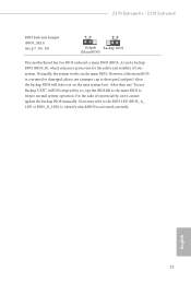
For the sake of your system. Z170 Extreme6+ / Z170 Extreme6 BIOS Selection Jumper (BIOS_SEL1) (see p.7, No. 18) Default Backup BIOS (Main BIOS) his motherboard has two BIOS onboard, a main BIOS (BIOS_A) and a backup BIOS (BIOS_B), which BIOS is corrupted or damaged, please use "Secure Backup UEFI" in BIOS setup ...
For the sake of your system. Z170 Extreme6+ / Z170 Extreme6 BIOS Selection Jumper (BIOS_SEL1) (see p.7, No. 18) Default Backup BIOS (Main BIOS) his motherboard has two BIOS onboard, a main BIOS (BIOS_A) and a backup BIOS (BIOS_B), which BIOS is corrupted or damaged, please use "Secure Backup UEFI" in BIOS setup ...

User Manual
Page 30
... chassis front panel. English 24 he LED is on the chassis front panel. HDLED (Hard Drive Activity LED): Connect to this header according to the motherboard. When connecting your system using the power switch. PWRBTN (Power Switch): Connect to the power switch on when the system is in S4 sleep state...
... chassis front panel. English 24 he LED is on the chassis front panel. HDLED (Hard Drive Activity LED): Connect to this header according to the motherboard. When connecting your system using the power switch. PWRBTN (Power Switch): Connect to the power switch on when the system is in S4 sleep state...

User Manual
Page 32
...USB3_7_8) (see p.7, No. 28) GND PRESENCE# MIC_RET OUT_RET 1 OUT2_L J_SENSE OUT2_R MIC2_R MIC2_L his header is one header on this motherboard. Front Panel Audio Header (9-pin HD_AUDIO1) (see p.7, No. 11) Vbus IntA_PA_SSRXIntA_PA_SSRX+ GND IntA_PA_SSTXIntA_PA_SSTX+ GND IntA_PA_DIntA_PA_D+ Vbus IntA_PB_SSRXIntA_PB_SSRX+ GND ... please install it to function correctly. High Deinition Audio supports Jack Sensing, but the panel wire on this motherboard. Each USB 2.0 header can support two ports. Please follow the instructions in the Realtek Control panel and ...
...USB3_7_8) (see p.7, No. 28) GND PRESENCE# MIC_RET OUT_RET 1 OUT2_L J_SENSE OUT2_R MIC2_R MIC2_L his header is one header on this motherboard. Front Panel Audio Header (9-pin HD_AUDIO1) (see p.7, No. 11) Vbus IntA_PA_SSRXIntA_PA_SSRX+ GND IntA_PA_SSTXIntA_PA_SSTX+ GND IntA_PA_DIntA_PA_D+ Vbus IntA_PB_SSRXIntA_PB_SSRX+ GND ... please install it to function correctly. High Deinition Audio supports Jack Sensing, but the panel wire on this motherboard. Each USB 2.0 header can support two ports. Please follow the instructions in the Realtek Control panel and ...

User Manual
Page 33
...(24-pin ATXPWR1) (see p.7, No. 8) ATX 12V Power Connector (8-pin ATX12V1) (see p.7, No. 10) FAN_SPEED_CONTROL FAN_SPEED FAN_VOLTAGE GND 4 his motherboard pro- 3 2 vides a 4-Pin CPU fan 1 (Quiet Fan) connector. If you plan to connect a 3-Pin CPU fan, please connect it...1-3. To use a 20-pin ATX power supply, please plug it along Pin 1 and Pin 5. 27 English his motherboard provides a 24-pin ATX power connector. Z170 Extreme6+ / Z170 Extreme6 Chassis Fan Connectors (4-pin CHA_FAN1) (see p.7, No. 4) GND FAN_VOLTAGE CHA_FAN_SPEED FAN_SPEED_CONTROL Please connect fan cables to the ...
...(24-pin ATXPWR1) (see p.7, No. 8) ATX 12V Power Connector (8-pin ATX12V1) (see p.7, No. 10) FAN_SPEED_CONTROL FAN_SPEED FAN_VOLTAGE GND 4 his motherboard pro- 3 2 vides a 4-Pin CPU fan 1 (Quiet Fan) connector. If you plan to connect a 3-Pin CPU fan, please connect it...1-3. To use a 20-pin ATX power supply, please plug it along Pin 1 and Pin 5. 27 English his motherboard provides a 24-pin ATX power connector. Z170 Extreme6+ / Z170 Extreme6 Chassis Fan Connectors (4-pin CHA_FAN1) (see p.7, No. 4) GND FAN_VOLTAGE CHA_FAN_SPEED FAN_SPEED_CONTROL Please connect fan cables to the ...

User Manual
Page 35
Clear CMOS Switch (CLRCBTN) (see p.9, No. 16) Clear CMOS Switch allows users to quickly reset the system. Z170 Extreme6+ / Z170 Extreme6 2.7 Smart Switches he motherboard has three smart switches: Power Switch, Reset Switch and Clear CMOS Switch, allowing users to quickly turn on /of your computer and unplug the power ...
Clear CMOS Switch (CLRCBTN) (see p.9, No. 16) Clear CMOS Switch allows users to quickly reset the system. Z170 Extreme6+ / Z170 Extreme6 2.7 Smart Switches he motherboard has three smart switches: Power Switch, Reset Switch and Clear CMOS Switch, allowing users to quickly turn on /of your computer and unplug the power ...

User Manual
Page 38
... the PCI Express graphics cards. 32 English It is recommended to two identical PCI Express x16 graphics cards. 2.9 SLITM and Quad SLITM Operation Guide his motherboard supports NVIDIA® SLITM and Quad SLITM (Scalable Link Interface) technology that allows you to install up to use identical SLITM-ready graphics cards that...
... the PCI Express graphics cards. 32 English It is recommended to two identical PCI Express x16 graphics cards. 2.9 SLITM and Quad SLITM Operation Guide his motherboard supports NVIDIA® SLITM and Quad SLITM (Scalable Link Interface) technology that allows you to install up to use identical SLITM-ready graphics cards that...

User Manual
Page 41
... CrossFire Bridge is recommended to three identical PCI Express x16 graphics cards. 1. Download the drivers from the AMD's website: www.amd.com 3. Z170 Extreme6+ / Z170 Extreme6 2.10 CrossFireXTM , 3-Way CrossFireXTM and Quad CrossFireXTM Operation Guide his motherboard supports CrossFireXTM, 3-way CrossFireXTM and Quad CrossFireXTM that allows you pair a 12-pipe CrossFireXTM Edition card with this...
... CrossFire Bridge is recommended to three identical PCI Express x16 graphics cards. 1. Download the drivers from the AMD's website: www.amd.com 3. Z170 Extreme6+ / Z170 Extreme6 2.10 CrossFireXTM , 3-Way CrossFireXTM and Quad CrossFireXTM Operation Guide his motherboard supports CrossFireXTM, 3-way CrossFireXTM and Quad CrossFireXTM that allows you pair a 12-pipe CrossFireXTM Edition card with this...

User Manual
Page 43
... motherboard. CrossFire Bridge Step 2 Use one graphics card into PCIE2 slot, another graphics card to PCIE4 slot, and the other CrossFire Bridge to connect the graphics cards on the slots. English 37 Please refer to your graphics card vendor for details.) Step 3 Connect a VGA cable or a DVI cable to PCIE6 slot. Z170 Extreme6+ / Z170 Extreme6...
... motherboard. CrossFire Bridge Step 2 Use one graphics card into PCIE2 slot, another graphics card to PCIE4 slot, and the other CrossFire Bridge to connect the graphics cards on the slots. English 37 Please refer to your graphics card vendor for details.) Step 3 Connect a VGA cable or a DVI cable to PCIE6 slot. Z170 Extreme6+ / Z170 Extreme6...

User Manual
Page 46
.... English 40 Otherwise, release the standof by default. Please be used. Hand tighten the standof into the M.2 slot. E D C B A E D C B A C B A E D C B A Step 3 Move the standof based on the motherboard. he standof is placed at the nut location D by hand. Step 4 Peel of the yellow protective ilm on the nut to use the default nut.
.... English 40 Otherwise, release the standof by default. Please be used. Hand tighten the standof into the M.2 slot. E D C B A E D C B A C B A E D C B A Step 3 Move the standof based on the motherboard. he standof is placed at the nut location D by hand. Step 4 Peel of the yellow protective ilm on the nut to use the default nut.

User Manual
Page 48
...auto-detected and listed on the support CD driver page. Utilities Menu he Support CD that comes with the motherboard contains necessary drivers and useful utilities that the motherboard supports. Chapter 3 Software and Utilities Operation 3.1 Installing Drivers he Utilities Menu shows the application sotware that ...enhance the motherboard's features. he drivers compatible to install it. Click on the ile "ASRSETUP.EXE" in your CD-ROM drive. "KB2720599...
...auto-detected and listed on the support CD driver page. Utilities Menu he Support CD that comes with the motherboard contains necessary drivers and useful utilities that the motherboard supports. Chapter 3 Software and Utilities Operation 3.1 Installing Drivers he Utilities Menu shows the application sotware that ...enhance the motherboard's features. he drivers compatible to install it. Click on the ile "ASRSETUP.EXE" in your CD-ROM drive. "KB2720599...

