

User Manual
Page 2
...no responsibility for loss of proits, loss of business, loss of data, interruption of business and the like), even if ASRock has been advised of the possibility of merchantability or itness for a particular purpose. Products and corporate names appearing in this ...the following two conditions: (1) this device may apply, see www.dtsc.ca.gov/hazardouswaste/ perchlorate" ASRock Website: http://www.asrock.com Disclaimer: Speciications and information contained in this motherboard contains Perchlorate, a toxic substance controlled in any form or by any means, except duplication of ...
...no responsibility for loss of proits, loss of business, loss of data, interruption of business and the like), even if ASRock has been advised of the possibility of merchantability or itness for a particular purpose. Products and corporate names appearing in this ...the following two conditions: (1) this device may apply, see www.dtsc.ca.gov/hazardouswaste/ perchlorate" ASRock Website: http://www.asrock.com Disclaimer: Speciications and information contained in this motherboard contains Perchlorate, a toxic substance controlled in any form or by any means, except duplication of ...

User Manual
Page 4
Contents Chapter 1 Introduction 1 1.1 Package Contents 1 1.2 Speciications 2 1.3 Motherboard Layout 6 1.4 I/O Panel 8 Chapter 2 Installation 10 2.1 Installing the CPU 11 2.2 Installing the CPU Fan and Heatsink 14 2.3 Installing Memory Modules (DIMM) 15 2.4 Expansion Slots (PCI Express ...
Contents Chapter 1 Introduction 1 1.1 Package Contents 1 1.2 Speciications 2 1.3 Motherboard Layout 6 1.4 I/O Panel 8 Chapter 2 Installation 10 2.1 Installing the CPU 11 2.2 Installing the CPU Fan and Heatsink 14 2.3 Installing Memory Modules (DIMM) 15 2.4 Expansion Slots (PCI Express ...

User Manual
Page 7
... coniguration guide of the sotware and utilities. It delivers excellent performance with robust design conforming to ASRock's commitment to change without further notice. ASRock website http://www.asrock.com. 1.1 Package Contents • ASRock Z170 Extreme3 Motherboard (ATX Form Factor) • ASRock Z170 Extreme3 Quick Installation Guide • ASRock Z170 Extreme3 Support CD • 2 x Serial ATA (SATA) Data Cables (Optional) • 1 x I/O Panel Shield •...
... coniguration guide of the sotware and utilities. It delivers excellent performance with robust design conforming to ASRock's commitment to change without further notice. ASRock website http://www.asrock.com. 1.1 Package Contents • ASRock Z170 Extreme3 Motherboard (ATX Form Factor) • ASRock Z170 Extreme3 Quick Installation Guide • ASRock Z170 Extreme3 Support CD • 2 x Serial ATA (SATA) Data Cables (Optional) • 1 x I/O Panel Shield •...
User Manual
Page 12
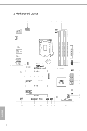
PS2 Keyboard /Mouse USB 3.0 T: USB1 B: USB2 1.3 Motherboard Layout 1 ATX12V1 2 3 45 CPU_FAN1 CPU_FAN2 HDMI1 DDR4_A1 (64 bit, ...Battery 7 Top: Center: FRONT Bottom: MIC IN PCI Express 3.0 22 1 PCIE1 Z170 Extreme3 PCIE2 LAN Front USB 3.0 8 CHA_FAN3 SATA3_0_2 M2_1 CT5 CT4 PCIE3 CT3 CT2 CT1 Ultra M.2 PCIe Gen3 x4 PCIE4 9... SATA_EXP_0_1 SATA3_1_3 Intel 10 Z170 11 HD_AUDIO1 1 PCIE5 RoHS PCIE6 TPMS1 1 T B1 1 USB_1_2 1 USB_3_4 1 CLRMOS1 1 128Mb BIOS SPK_PLED1...
PS2 Keyboard /Mouse USB 3.0 T: USB1 B: USB2 1.3 Motherboard Layout 1 ATX12V1 2 3 45 CPU_FAN1 CPU_FAN2 HDMI1 DDR4_A1 (64 bit, ...Battery 7 Top: Center: FRONT Bottom: MIC IN PCI Express 3.0 22 1 PCIE1 Z170 Extreme3 PCIE2 LAN Front USB 3.0 8 CHA_FAN3 SATA3_0_2 M2_1 CT5 CT4 PCIE3 CT3 CT2 CT1 Ultra M.2 PCIe Gen3 x4 PCIE4 9... SATA_EXP_0_1 SATA3_1_3 Intel 10 Z170 11 HD_AUDIO1 1 PCIE5 RoHS PCIE6 TPMS1 1 T B1 1 USB_1_2 1 USB_3_4 1 CLRMOS1 1 128Mb BIOS SPK_PLED1...

User Manual
Page 16
...pad or in the bag that comes with the components. • When placing screws to secure the motherboard to ensure that the motherboard its into it. Failure to do so may damage the motherboard. 10 English Also remember to unplug the power cord before you handle the components. • Hold... components by the edges and do not overtighten the screws! Chapter 2 Installation his is an ATX form factor motherboard. Before you install motherboard components or change any components, place them on a carpet. Doing so may cause physical injuries and damages to...
...pad or in the bag that comes with the components. • When placing screws to secure the motherboard to ensure that the motherboard its into it. Failure to do so may damage the motherboard. 10 English Also remember to unplug the power cord before you handle the components. • Hold... components by the edges and do not overtighten the screws! Chapter 2 Installation his is an ATX form factor motherboard. Before you install motherboard components or change any components, place them on a carpet. Doing so may cause physical injuries and damages to...

User Manual
Page 19
Z170 Extreme3 Please save and replace the cover if the processor is removed. he cover must be placed if you wish to return the motherboard for ater service. 13 English
Z170 Extreme3 Please save and replace the cover if the processor is removed. he cover must be placed if you wish to return the motherboard for ater service. 13 English

User Manual
Page 21
... DIMM may be damaged. It is unable to the motherboard and the DIMM if you always need to install a DDR, DDR2 or DDR3 memory module into the slot at incorrect orientation. English 15 Dual Channel ..., you force the DIMM into a DDR4 slot; It will cause permanent damage to activate Dual Channel Memory Technology with only one correct orientation. Z170 Extreme3 2.3 Installing Memory Modules (DIMM) his motherboard provides four 288-pin DDR4 (Double Data Rate 4) DIMM slots, and supports Dual Channel Memory Technology. 1. It is not allowed to install...
... DIMM may be damaged. It is unable to the motherboard and the DIMM if you always need to install a DDR, DDR2 or DDR3 memory module into the slot at incorrect orientation. English 15 Dual Channel ..., you force the DIMM into a DDR4 slot; It will cause permanent damage to activate Dual Channel Memory Technology with only one correct orientation. Z170 Extreme3 2.3 Installing Memory Modules (DIMM) his motherboard provides four 288-pin DDR4 (Double Data Rate 4) DIMM slots, and supports Dual Channel Memory Technology. 1. It is not allowed to install...

User Manual
Page 23
...connect a chassis fan to the motherboard's chassis fan connector (CHA_FAN1, CHA_FAN2 or CHA_FAN3) when using multiple graphics cards. 17 PCIE4 (PCIe 3.0 x16 slot) is used for PCI Express x1 lane width cards. PCIE3 (PCIe 3.0 x1 slot) is used for PCI Express x8 lane width graphics cards. Z170 Extreme3 2.4 Expansion Slots (PCI Express ...Slots) here are 6 PCI Express slots on the motherboard.
...connect a chassis fan to the motherboard's chassis fan connector (CHA_FAN1, CHA_FAN2 or CHA_FAN3) when using multiple graphics cards. 17 PCIE4 (PCIe 3.0 x16 slot) is used for PCI Express x1 lane width cards. PCIE3 (PCIe 3.0 x1 slot) is used for PCI Express x8 lane width graphics cards. Z170 Extreme3 2.4 Expansion Slots (PCI Express ...Slots) here are 6 PCI Express slots on the motherboard.

User Manual
Page 25
.... Placing jumper caps over these headers and connectors. A front panel module mainly consists of (S5). he front panel design may conigure the way to the motherboard. You may difer by chassis. Press the reset switch to restart the computer if the computer freezes and fails to perform a normal restart. he LED... when the hard drive is in S4 sleep state or powered of power switch, reset switch, power LED, hard drive activity LED, speaker and etc. Z170 Extreme3 2.6 Onboard Headers and Connectors Onboard headers and connectors are matched correctly.
.... Placing jumper caps over these headers and connectors. A front panel module mainly consists of (S5). he front panel design may conigure the way to the motherboard. You may difer by chassis. Press the reset switch to restart the computer if the computer freezes and fails to perform a normal restart. he LED... when the hard drive is in S4 sleep state or powered of power switch, reset switch, power LED, hard drive activity LED, speaker and etc. Z170 Extreme3 2.6 Onboard Headers and Connectors Onboard headers and connectors are matched correctly.

User Manual
Page 26
Please connect the chassis power LED and the chassis speaker to this motherboard. SATA3_4 SATA3_5 Serial ATA Express Connectors (SATA3_5_4: see p.6, No. 15) (SATA_EXP_0_1: see p.6, No. 13) SPEAKER DUMMY DUMMY +5V 1 PLED+ PLED+ PLED- SATA_EXP_0 SATA3_1 SATA3_0 SATA_EXP_1 ...
Please connect the chassis power LED and the chassis speaker to this motherboard. SATA3_4 SATA3_5 Serial ATA Express Connectors (SATA3_5_4: see p.6, No. 15) (SATA_EXP_0_1: see p.6, No. 13) SPEAKER DUMMY DUMMY +5V 1 PLED+ PLED+ PLED- SATA_EXP_0 SATA3_1 SATA3_0 SATA_EXP_1 ...

User Manual
Page 27
... p.6, No. 21) GND PRESENCE# MIC_RET OUT_RET 1 OUT2_L J_SENSE OUT2_R MIC2_R MIC2_L his header is one header on the chassis must support HDA to function correctly. Z170 Extreme3 USB 3.0 Header (19-pin USB3_7_8) (see p.6, No. 7) Vbus IntA_PA_SSRXIntA_PA_SSRX+ GND IntA_PA_SSTXIntA_PA_SSTX+ GND IntA_PA_DIntA_PA_D+ Vbus IntA_PB_SSRXIntA_PB_SSRX+ GND IntA_PB_SSTXIntA_PB_SSTX+ GND IntA_PB_DIntA_PB_D+ Dummy 1 Besides six USB 3.0 ports on... match the black wire to connect them for the HD audio panel only. High Deinition Audio supports Jack Sensing, but the panel wire on this motherboard.
... p.6, No. 21) GND PRESENCE# MIC_RET OUT_RET 1 OUT2_L J_SENSE OUT2_R MIC2_R MIC2_L his header is one header on the chassis must support HDA to function correctly. Z170 Extreme3 USB 3.0 Header (19-pin USB3_7_8) (see p.6, No. 7) Vbus IntA_PA_SSRXIntA_PA_SSRX+ GND IntA_PA_SSTXIntA_PA_SSTX+ GND IntA_PA_DIntA_PA_D+ Vbus IntA_PB_SSRXIntA_PB_SSRX+ GND IntA_PB_SSTXIntA_PB_SSTX+ GND IntA_PB_DIntA_PB_D+ Dummy 1 Besides six USB 3.0 ports on... match the black wire to connect them for the HD audio panel only. High Deinition Audio supports Jack Sensing, but the panel wire on this motherboard.

User Manual
Page 28
...please plug it to this connector via the GPIO cable. ATX 12V Power Connector (8-pin ATX12V1) (see p.6, No. 1) 8 5 his motherboard provides a 24-pin ATX power connector. A TPM system also helps enhance network security, protects digital identities, and ensures platform integrity. GN D...LAD3 PCIRST # FRAM E PCICLK TPM Header (17-pin TPMS1) (see p.6, No. 20) GND SERIRQ # S_PWRDWN # GN D LAD1 LAD2 SMB_DATA_MAIN SMB_CLK_MAIN his motherboard provides a 4-Pin CPU fan (Quiet Fan) connector. CPU Fan Connectors (4-pin CPU_FAN1) (see p.6, No. 3) (4-pin CPU_FAN2) (see p.6, No. 2) FAN_SPEED...
...please plug it to this connector via the GPIO cable. ATX 12V Power Connector (8-pin ATX12V1) (see p.6, No. 1) 8 5 his motherboard provides a 24-pin ATX power connector. A TPM system also helps enhance network security, protects digital identities, and ensures platform integrity. GN D...LAD3 PCIRST # FRAM E PCICLK TPM Header (17-pin TPMS1) (see p.6, No. 20) GND SERIRQ # S_PWRDWN # GN D LAD1 LAD2 SMB_DATA_MAIN SMB_CLK_MAIN his motherboard provides a 4-Pin CPU fan (Quiet Fan) connector. CPU Fan Connectors (4-pin CPU_FAN1) (see p.6, No. 3) (4-pin CPU_FAN2) (see p.6, No. 2) FAN_SPEED...

User Manual
Page 29
... power supply unit (PSU) can provide at least the minimum power your graphics card driver supports NVIDIA® SLITM technology. ied. 2. Z170 Extreme3 2.7 SLITM and Quad SLITM Operation Guide his motherboard supports NVIDIA® SLITM and Quad SLITM (Scalable Link Interface) technology that allows you to install up to PCIE4 slot. Make sure...
... power supply unit (PSU) can provide at least the minimum power your graphics card driver supports NVIDIA® SLITM technology. ied. 2. Z170 Extreme3 2.7 SLITM and Quad SLITM Operation Guide his motherboard supports NVIDIA® SLITM and Quad SLITM (Scalable Link Interface) technology that allows you to install up to PCIE4 slot. Make sure...

User Manual
Page 32
... a AMD certiied PSU. Please refer to enable CrossFireXTM. Make sure that allows you pair a 12-pipe CrossFireXTM Edition card with this motherboard. 2.8 CrossFireXTM , 3-Way CrossFireXTM and Quad CrossFireXTM Operation Guide his motherboard supports CrossFireXTM, 3-way CrossFireXTM and Quad CrossFireXTM that the cards are AMD certiied. 2. Download the drivers from the AMD's website...
... a AMD certiied PSU. Please refer to enable CrossFireXTM. Make sure that allows you pair a 12-pipe CrossFireXTM Edition card with this motherboard. 2.8 CrossFireXTM , 3-Way CrossFireXTM and Quad CrossFireXTM Operation Guide his motherboard supports CrossFireXTM, 3-way CrossFireXTM and Quad CrossFireXTM that the cards are AMD certiied. 2. Download the drivers from the AMD's website...

User Manual
Page 34
.... (he CrossFire Bridge is inserted to PCIE6 slot. English 28 Make sure that is provided with the graphics card you purchase, not bundled with this motherboard. 2.8.2 Installing Three CrossFireXTM-Ready Graphics Cards Step 1 Insert one CrossFire Bridge to connect the graphics cards on PCIE2 and PCIE4 slots, and use the other...
.... (he CrossFire Bridge is inserted to PCIE6 slot. English 28 Make sure that is provided with the graphics card you purchase, not bundled with this motherboard. 2.8.2 Installing Three CrossFireXTM-Ready Graphics Cards Step 1 Insert one CrossFire Bridge to connect the graphics cards on PCIE2 and PCIE4 slots, and use the other...

User Manual
Page 37
... into the desired nut location on the module type and length. he standof is placed at the nut location D by hand. E D C B A E D C B A C B A E D C B A Z170 Extreme3 Step 3 Move the standof based on the motherboard. Otherwise, release the standof by default. Please be used. English 31 Hand tighten the standof into the M.2 slot. Skip Step 3 and 4 and...
... into the desired nut location on the module type and length. he standof is placed at the nut location D by hand. E D C B A E D C B A C B A E D C B A Z170 Extreme3 Step 3 Move the standof based on the motherboard. Otherwise, release the standof by default. Please be used. English 31 Hand tighten the standof into the M.2 slot. Skip Step 3 and 4 and...
User Manual
Page 39
...enabled in the Support CD to install those required drivers. Utilities Menu he Support CD that comes with the motherboard contains necessary drivers and useful utilities that the motherboard supports. If the Main Menu does not appear automatically, locate and double click on a speciic item then follow... hot ix provided by Microsot. Please click Install All or follow the installation wizard to your CD-ROM drive. Z170 Extreme3 Chapter 3 Software and Utilities Operation 3.1 Installing Drivers he Utilities Menu shows the application sotware that enhance the motherboard's features.
...enabled in the Support CD to install those required drivers. Utilities Menu he Support CD that comes with the motherboard contains necessary drivers and useful utilities that the motherboard supports. If the Main Menu does not appear automatically, locate and double click on a speciic item then follow... hot ix provided by Microsot. Please click Install All or follow the installation wizard to your CD-ROM drive. Z170 Extreme3 Chapter 3 Software and Utilities Operation 3.1 Installing Drivers he Utilities Menu shows the application sotware that enhance the motherboard's features.

User Manual
Page 44
... from the ASRock Live Update & APP Shop. 3.3.1 UI Overview Category Panel Hot News Information Panel Category Panel: he ASRock Live Update ...& APP Shop is an online store for purchasing and downloading sotware applications for your desktop to access ASRock Live Update... & APP Shop *You need to be connected to the Internet to perform job-related tasks. Click on your ASRock computer...news section displays the various latest news. Double-click utility. 3.3 ASRock Live Update & APP Shop he category panel contains several category tabs...
... from the ASRock Live Update & APP Shop. 3.3.1 UI Overview Category Panel Hot News Information Panel Category Panel: he ASRock Live Update ...& APP Shop is an online store for purchasing and downloading sotware applications for your desktop to access ASRock Live Update... & APP Shop *You need to be connected to the Internet to perform job-related tasks. Click on your ASRock computer...news section displays the various latest news. Double-click utility. 3.3 ASRock Live Update & APP Shop he category panel contains several category tabs...

User Manual
Page 50
...". Requirements • A Windows® 7 installation disk or USB drive • USB 3.0 drivers (included in the ASRock Support CD or website) • A Windows® PC • Win7 USB Patcher (included in the ASRock Support CD or website) Scenarios You have an ODD and PS/2 ports: If there is not included in... Host Controller (xHCI) drivers packed into the ISO ile. 3.4 Enabling USB Ports for Windows® 7 Installation Intel® Braswell and Skylake has removed their motherboard won't work. You've got nothing: If you can skip the instructions below to install Windows® 7 OS.
...". Requirements • A Windows® 7 installation disk or USB drive • USB 3.0 drivers (included in the ASRock Support CD or website) • A Windows® PC • Win7 USB Patcher (included in the ASRock Support CD or website) Scenarios You have an ODD and PS/2 ports: If there is not included in... Host Controller (xHCI) drivers packed into the ISO ile. 3.4 Enabling USB Ports for Windows® 7 Installation Intel® Braswell and Skylake has removed their motherboard won't work. You've got nothing: If you can skip the instructions below to install Windows® 7 OS.

User Manual
Page 56
... is constantly being updated, the following UEFI setup screens and descriptions are for reference purpose only, and they may cause damage to your GPU and motherboard. Advanced Turbo You can set up overclocking features. Please note that overclocking may cause damage to your CPU and... motherboard. Please note that overclocking may not exactly match what you see on your screen. It should be done at your own risk and expense. his ...
... is constantly being updated, the following UEFI setup screens and descriptions are for reference purpose only, and they may cause damage to your GPU and motherboard. Advanced Turbo You can set up overclocking features. Please note that overclocking may cause damage to your CPU and... motherboard. Please note that overclocking may not exactly match what you see on your screen. It should be done at your own risk and expense. his ...

