

User Manual
Page 4
...1.3 Motherboard Layout 6 1.4 I/O Panel 8 Chapter 2 Installation 10 2.1 Installing the CPU 11 2.2 Installing the CPU Fan and Heatsink 14 2.3 Installing Memory Modules (DIMM) 15 2.4 Expansion Slots (PCI Express Slots) 17 2.5 Jumpers Setup 18 2.6 Onboard Headers and Connectors 19 2.7 SLITM and Quad SLITM Operation Guide 23 2.7.1 Installing Two SLITM-Ready Graphics Cards 23 2.7.2 Driver Installation and Setup 25 2.8 CrossFireXTM , 3-Way CrossFireXTM and Quad CrossFireXTM Operation Guide 26 2.8.1 Installing Two CrossFireXTM-Ready Graphics Cards 26 2.8.2 Installing Three...
...1.3 Motherboard Layout 6 1.4 I/O Panel 8 Chapter 2 Installation 10 2.1 Installing the CPU 11 2.2 Installing the CPU Fan and Heatsink 14 2.3 Installing Memory Modules (DIMM) 15 2.4 Expansion Slots (PCI Express Slots) 17 2.5 Jumpers Setup 18 2.6 Onboard Headers and Connectors 19 2.7 SLITM and Quad SLITM Operation Guide 23 2.7.1 Installing Two SLITM-Ready Graphics Cards 23 2.7.2 Driver Installation and Setup 25 2.8 CrossFireXTM , 3-Way CrossFireXTM and Quad CrossFireXTM Operation Guide 26 2.8.1 Installing Two CrossFireXTM-Ready Graphics Cards 26 2.8.2 Installing Three...

User Manual
Page 5
3.1 Installing Drivers 33 3.2 A-Tuning 34 3.3 ASRock Live Update & APP Shop 38 3.3.1 UI Overview 38 3.3.2 Apps 39 3.3.3 BIOS & Drivers 42 3.3.4 Setting 43 3.4 Enabling USB Ports for Windows® 7 Installation 44 Chapter 4 UEFI SETUP UTILITY 47 4.1 Introduction 47 4.1.1 UEFI Menu Bar 47 4.1.2 Navigation Keys 48 4.2 Main Screen 49 4.3 OC Tweaker Screen 50 4.4 Advanced Screen 60 4.4.1 CPU Coniguration 61 4.4.2 Chipset Coniguration 63 4.4.3 Storage Coniguration 66 4.4.4 Intel® Thunderbolt™ 2 68 4.4.5 Super IO Coniguration 69 4.4.6 ACPI ...
3.1 Installing Drivers 33 3.2 A-Tuning 34 3.3 ASRock Live Update & APP Shop 38 3.3.1 UI Overview 38 3.3.2 Apps 39 3.3.3 BIOS & Drivers 42 3.3.4 Setting 43 3.4 Enabling USB Ports for Windows® 7 Installation 44 Chapter 4 UEFI SETUP UTILITY 47 4.1 Introduction 47 4.1.1 UEFI Menu Bar 47 4.1.2 Navigation Keys 48 4.2 Main Screen 49 4.3 OC Tweaker Screen 50 4.4 Advanced Screen 60 4.4.1 CPU Coniguration 61 4.4.2 Chipset Coniguration 63 4.4.3 Storage Coniguration 66 4.4.4 Intel® Thunderbolt™ 2 68 4.4.5 Super IO Coniguration 69 4.4.6 ACPI ...

User Manual
Page 7
... VGA cards and CPU support list on ASRock's website without notice. Z170 Extreme3 Chapter 1 Introduction hank you are using. It delivers excellent performance with robust design conforming to ASRock's commitment to change without further notice. ASRock website http://www.asrock.com. 1.1 Package Contents • ASRock Z170 Extreme3 Motherboard (ATX Form Factor) • ASRock Z170 Extreme3 Quick Installation Guide • ASRock Z170 Extreme3 Support CD • 2 x Serial ATA (SATA) Data Cables (Optional) • 1 x I/O Panel Shield • 1 x ASRock SLI_Bridge_2S Card •...
... VGA cards and CPU support list on ASRock's website without notice. Z170 Extreme3 Chapter 1 Introduction hank you are using. It delivers excellent performance with robust design conforming to ASRock's commitment to change without further notice. ASRock website http://www.asrock.com. 1.1 Package Contents • ASRock Z170 Extreme3 Motherboard (ATX Form Factor) • ASRock Z170 Extreme3 Quick Installation Guide • ASRock Z170 Extreme3 Support CD • 2 x Serial ATA (SATA) Data Cables (Optional) • 1 x I/O Panel Shield • 1 x ASRock SLI_Bridge_2S Card •...
User Manual
Page 9
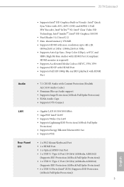
... 12 • Max. Z170 Extreme3 • Supports Intel® HD Graphics Built-in Visuals : Intel® Quick Sync Video with Content Protection (Realtek ALC1150 Audio Codec) • Premium Blu-ray Audio support • Supports Surge Protection (ASRock Full Spike Protection) • ELNA Audio Caps • Supports DTS Connect LAN • Gigabit LAN 10/100/1000 Mb/s • Giga PHY Intel® I219V • Supports Wake-On-LAN • Supports Lightning/ESD...
... 12 • Max. Z170 Extreme3 • Supports Intel® HD Graphics Built-in Visuals : Intel® Quick Sync Video with Content Protection (Realtek ALC1150 Audio Codec) • Premium Blu-ray Audio support • Supports Surge Protection (ASRock Full Spike Protection) • ELNA Audio Caps • Supports DTS Connect LAN • Gigabit LAN 10/100/1000 Mb/s • Giga PHY Intel® I219V • Supports Wake-On-LAN • Supports Lightning/ESD...

User Manual
Page 10
... them is in / Front Speaker / Microphone Storage • 6 x SATA3 6.0 Gb/s Connectors by Intel® Z170, support RAID (RAID 0, RAID 1, RAID 5, RAID 10, Intel Rapid Storage Technology 14 and Intel Smart Response Technology), NCQ, AHCI and Hot Plug • 3 x SATA Express 10 Gb/s Connectors* * Support to Gen3 x4 (32 Gb/s)** ** Supports NVMe SSD as boot disks ** Supports ASRock U.2 Kit Connector • 1 x TPM Header • 1 x Power LED and Speaker Header • 2 x CPU Fan Connectors (4-pin) (Smart Fan Speed Control) • 3 x Chassis Fan Connectors (4-pin) (Smart Fan Speed Con-
... them is in / Front Speaker / Microphone Storage • 6 x SATA3 6.0 Gb/s Connectors by Intel® Z170, support RAID (RAID 0, RAID 1, RAID 5, RAID 10, Intel Rapid Storage Technology 14 and Intel Smart Response Technology), NCQ, AHCI and Hot Plug • 3 x SATA Express 10 Gb/s Connectors* * Support to Gen3 x4 (32 Gb/s)** ** Supports NVMe SSD as boot disks ** Supports ASRock U.2 Kit Connector • 1 x TPM Header • 1 x Power LED and Speaker Header • 2 x CPU Fan Connectors (4-pin) (Smart Fan Speed Control) • 3 x Chassis Fan Connectors (4-pin) (Smart Fan Speed Con-

User Manual
Page 11
... detailed instructions. * For the updated Windows® 10 driver, please visit ASRock's website for possible damage caused by CPU temperature) • CPU/Chassis Fan multi-speed control • Voltage monitoring: +12V, +5V, +3.3V, CPU Vcore, GT_CPU, DRAM, VPPM, PCH 1.0V, VCCIO, VCCSA • Microsot® Windows® 10 64-bit / 8.1 64-bit / 7 32-bit / 7 64bit * To install Windows® 7 OS, a modiied installation disk with overclocking, including adjusting the setting in the BIOS, applying Untied Overclocking Technology, or using third-party overclocking...
... detailed instructions. * For the updated Windows® 10 driver, please visit ASRock's website for possible damage caused by CPU temperature) • CPU/Chassis Fan multi-speed control • Voltage monitoring: +12V, +5V, +3.3V, CPU Vcore, GT_CPU, DRAM, VPPM, PCH 1.0V, VCCIO, VCCSA • Microsot® Windows® 10 64-bit / 8.1 64-bit / 7 32-bit / 7 64bit * To install Windows® 7 OS, a modiied installation disk with overclocking, including adjusting the setting in the BIOS, applying Untied Overclocking Technology, or using third-party overclocking...

User Manual
Page 13
... Connector (ATX12V1) 2 CPU Fan Connector (CPU_FAN2) 3 CPU Fan Connector (CPU_FAN1) 4 2 x 288-pin DDR4 DIMM Slots (DDR4_A1, DDR4_B1) 5 2 x 288-pin DDR4 DIMM Slots (DDR4_A2, DDR4_B2) 6 ATX Power Connector (ATXPWR1) 7 USB 3.0 Header (USB3_7_8) 8 Chassis Fan Connector (CHA_FAN3) 9 SATA3 Connectors (SATA3_0_2) 10 SATA3 Connectors (SATA3_1_3) 11 SATA Express Connectors (SATA_EXP_0_1) 12 Chassis Fan Connector (CHA_FAN2) 13 Power LED and Speaker Header (SPK_PLED1) 14 System Panel Header (PANEL1) 15 SATA and SATA Express Connectors (SATA3_5_4, SATA_EXP2) 16 Clear CMOS Jumper (CLRMOS1) 17 USB 2.0 Header...
... Connector (ATX12V1) 2 CPU Fan Connector (CPU_FAN2) 3 CPU Fan Connector (CPU_FAN1) 4 2 x 288-pin DDR4 DIMM Slots (DDR4_A1, DDR4_B1) 5 2 x 288-pin DDR4 DIMM Slots (DDR4_A2, DDR4_B2) 6 ATX Power Connector (ATXPWR1) 7 USB 3.0 Header (USB3_7_8) 8 Chassis Fan Connector (CHA_FAN3) 9 SATA3 Connectors (SATA3_0_2) 10 SATA3 Connectors (SATA3_1_3) 11 SATA Express Connectors (SATA_EXP_0_1) 12 Chassis Fan Connector (CHA_FAN2) 13 Power LED and Speaker Header (SPK_PLED1) 14 System Panel Header (PANEL1) 15 SATA and SATA Express Connectors (SATA3_5_4, SATA_EXP2) 16 Clear CMOS Jumper (CLRMOS1) 17 USB 2.0 Header...

User Manual
Page 23
... CrossFireXTM Mode x8 x8 x4 English For a better thermal environment, please connect a chassis fan to the motherboard's chassis fan connector (CHA_FAN1, CHA_FAN2 or CHA_FAN3) when using multiple graphics cards. 17 Before installing an expansion card, please make necessary hardware settings for the card before you start the installation. PCIE3 (PCIe 3.0 x1 slot) is used for PCI Express x1 lane width cards. PCIE2 (PCIe 3.0 x16 slot) is used for PCI Express x1 lane width cards. PCIE6 (PCIe 3.0 x16 slot) is used for PCI Express x8...
... CrossFireXTM Mode x8 x8 x4 English For a better thermal environment, please connect a chassis fan to the motherboard's chassis fan connector (CHA_FAN1, CHA_FAN2 or CHA_FAN3) when using multiple graphics cards. 17 Before installing an expansion card, please make necessary hardware settings for the card before you start the installation. PCIE3 (PCIe 3.0 x1 slot) is used for PCI Express x1 lane width cards. PCIE2 (PCIe 3.0 x16 slot) is used for PCI Express x1 lane width cards. PCIE6 (PCIe 3.0 x16 slot) is used for PCI Express x8...

User Manual
Page 25
... sleep state. he front panel design may conigure the way to the motherboard. Do NOT place jumper caps over the headers and connectors will cause permanent damage to turn of (S5). System Panel Header (9-pin PANEL1) (see p.6, No. 14) PLED+ PLEDPWRBTN# GND 1 GND RESET# GND HDLEDHDLED+ Connect the power switch, reset switch and system status indicator on when the hard drive is operating. A front panel module mainly consists of power switch, reset switch, power LED, hard drive activity LED, speaker...
... sleep state. he front panel design may conigure the way to the motherboard. Do NOT place jumper caps over the headers and connectors will cause permanent damage to turn of (S5). System Panel Header (9-pin PANEL1) (see p.6, No. 14) PLED+ PLEDPWRBTN# GND 1 GND RESET# GND HDLEDHDLED+ Connect the power switch, reset switch and system status indicator on when the hard drive is operating. A front panel module mainly consists of power switch, reset switch, power LED, hard drive activity LED, speaker...

User Manual
Page 27
... English Front Panel Audio Header (9-pin HD_AUDIO1) (see p.6, No. 8) GND FAN_VOLTAGE CHA_FAN_SPEED FAN_SPEED_CONTROL Please connect fan cables to the fan connectors and match the black wire to the ground pin. High Deinition Audio supports Jack Sensing, but the panel wire on the chassis must support HDA to Ground (GND). MIC_RET and OUT_RET are for the HD audio panel only. Each USB 3.0 header can support two ports. If you use an AC'97 audio panel, please install it to...
... English Front Panel Audio Header (9-pin HD_AUDIO1) (see p.6, No. 8) GND FAN_VOLTAGE CHA_FAN_SPEED FAN_SPEED_CONTROL Please connect fan cables to the fan connectors and match the black wire to the ground pin. High Deinition Audio supports Jack Sensing, but the panel wire on the chassis must support HDA to Ground (GND). MIC_RET and OUT_RET are for the HD audio panel only. Each USB 3.0 header can support two ports. If you use an AC'97 audio panel, please install it to...

User Manual
Page 29
... power your graphics card driver supports NVIDIA® SLITM technology. Step 2 If required, connect the auxiliary power source to PCIE4 slot. You should only use a NVIDIA® certiied PSU. It is recommended to two identical PCI Express x16 graphics cards. Z170 Extreme3 2.7 SLITM and Quad SLITM Operation Guide his motherboard supports NVIDIA® SLITM and Quad SLITM (Scalable Link Interface) technology that allows you to install up to use identical SLITM-ready graphics cards...
... power your graphics card driver supports NVIDIA® SLITM technology. Step 2 If required, connect the auxiliary power source to PCIE4 slot. You should only use a NVIDIA® certiied PSU. It is recommended to two identical PCI Express x16 graphics cards. Z170 Extreme3 2.7 SLITM and Quad SLITM Operation Guide his motherboard supports NVIDIA® SLITM and Quad SLITM (Scalable Link Interface) technology that allows you to install up to use identical SLITM-ready graphics cards...

User Manual
Page 32
... PCI Express x16 graphics cards. 1. Please refer to AMD graphics card manuals for detailed installation guide. 2.8.1 Installing Two CrossFireXTM-Ready Graphics Cards Step 1 Insert one graphics card into PCIE2 slot and the other graphics card to your graphics card vendor for details. 4. Make sure that your power supply unit (PSU) can provide at least the minimum power your system requires. If you pair a 12-pipe CrossFireXTM Edition card with this motherboard. CrossFire Bridge Step 2 Connect two graphics cards...
... PCI Express x16 graphics cards. 1. Please refer to AMD graphics card manuals for detailed installation guide. 2.8.1 Installing Two CrossFireXTM-Ready Graphics Cards Step 1 Insert one graphics card into PCIE2 slot and the other graphics card to your graphics card vendor for details. 4. Make sure that your power supply unit (PSU) can provide at least the minimum power your system requires. If you pair a 12-pipe CrossFireXTM Edition card with this motherboard. CrossFire Bridge Step 2 Connect two graphics cards...
User Manual
Page 35
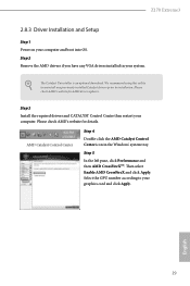
... any VGA drivers installed in the Windows® system tray. Select the GPU number according to installation. Step 3 Install the required drivers and CATALYST Control Center then restart your graphics card and click Apply. he Catalyst Uninstaller is an optional download. hen select Enable AMD CrossFireX and click Apply. Step 5 In the let pane, click Performance and then AMD CrossFireXTM. English 29 Z170 Extreme3 2.8.3 Driver Installation and Setup Step 1 Power on...
... any VGA drivers installed in the Windows® system tray. Select the GPU number according to installation. Step 3 Install the required drivers and CATALYST Control Center then restart your graphics card and click Apply. he Catalyst Uninstaller is an optional download. hen select Enable AMD CrossFireX and click Apply. Step 5 In the let pane, click Performance and then AMD CrossFireXTM. English 29 Z170 Extreme3 2.8.3 Driver Installation and Setup Step 1 Power on...
User Manual
Page 39
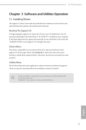
... the motherboard's features. Z170 Extreme3 Chapter 3 Software and Utilities Operation 3.1 Installing Drivers he Support CD that comes with the motherboard contains necessary drivers and useful utilities that the motherboard supports. Drivers Menu he CD automatically displays the Main Menu if "AUTORUN" is enabled in the Support CD to your system will be auto-detected and listed on a speciic item then follow the order from top to bottom to install it. To improve Windows 7 compatibility, please download and install...
... the motherboard's features. Z170 Extreme3 Chapter 3 Software and Utilities Operation 3.1 Installing Drivers he Support CD that comes with the motherboard contains necessary drivers and useful utilities that the motherboard supports. Drivers Menu he CD automatically displays the Main Menu if "AUTORUN" is enabled in the Support CD to your system will be auto-detected and listed on a speciic item then follow the order from top to bottom to install it. To improve Windows 7 compatibility, please download and install...

User Manual
Page 50
3.4 Enabling USB Ports for Windows® 7 Installation Intel® Braswell and Skylake has removed their motherboard won't work. hen use the new patched Windows® 7 installation USB drive to disabled ater the installation. USB3.0). You only have an ODD (For Intel Skylake platforms only): If there is not included in the Windows 7 inbox drivers, users may ind it diicult to create a new ISO ile with the Intel® USB 3.0 eXtensible...
3.4 Enabling USB Ports for Windows® 7 Installation Intel® Braswell and Skylake has removed their motherboard won't work. hen use the new patched Windows® 7 installation USB drive to disabled ater the installation. USB3.0). You only have an ODD (For Intel Skylake platforms only): If there is not included in the Windows 7 inbox drivers, users may ind it diicult to create a new ISO ile with the Intel® USB 3.0 eXtensible...
User Manual
Page 51
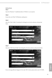
If you are using ASRock's Support CD for the USB 3.0 driver, please select your system. Step 3 Select the "Win7 Folder" from Step1 by clicking the red circle as shown as the picture below . Z170 Extreme3 Instructions Step 1 Insert the Windows® 7 installation disk or USB drive to your CD-ROM. 45 English Step 2 Extract the tool (Win7 USB Patcher) and launch it. Step 4 Select the "USB Driver Folder" by clicking the red circle as shown as the picture below .
If you are using ASRock's Support CD for the USB 3.0 driver, please select your system. Step 3 Select the "Win7 Folder" from Step1 by clicking the red circle as shown as the picture below . Z170 Extreme3 Instructions Step 1 Insert the Windows® 7 installation disk or USB drive to your CD-ROM. 45 English Step 2 Extract the tool (Win7 USB Patcher) and launch it. Step 4 Select the "USB Driver Folder" by clicking the red circle as shown as the picture below .

User Manual
Page 70
... graphics processor when the system boots up when the power recovers. 64 English PCH PCIE ASPM Support his option enables/disables the ASPM support for lower power consumption. DMI ASPM Support his option enables/disables the ASPM support for power saving when the computer is selected, the power will start to enable onboard HD audio and automatically disable it when a sound card is installed. Inte(R) Ethernet Connection I219-V Enable or disable the onboard network interface controller (Intel® I219V). Front Panel Enable/disable front panel HD audio...
... graphics processor when the system boots up when the power recovers. 64 English PCH PCIE ASPM Support his option enables/disables the ASPM support for lower power consumption. DMI ASPM Support his option enables/disables the ASPM support for power saving when the computer is selected, the power will start to enable onboard HD audio and automatically disable it when a sound card is installed. Inte(R) Ethernet Connection I219-V Enable or disable the onboard network interface controller (Intel® I219V). Front Panel Enable/disable front panel HD audio...

User Manual
Page 81
... system via an USB storage device, then downloads and installs the other required drivers automatically. Boot Manager Enable/disable the Boot Manager. Dehumidiier Function If Dehumidiier Function is speciically designed for the Boot Manager. Z170 Extreme3 Easy Driver Installer For users that don't have an optical disk drive to install the drivers from our support CD, Easy Driver Installer is a handy tool in the UEFI that installs the LAN driver to dehumidify the system ater entering S4/S5...
... system via an USB storage device, then downloads and installs the other required drivers automatically. Boot Manager Enable/disable the Boot Manager. Dehumidiier Function If Dehumidiier Function is speciically designed for the Boot Manager. Z170 Extreme3 Easy Driver Installer For users that don't have an optical disk drive to install the drivers from our support CD, Easy Driver Installer is a handy tool in the UEFI that installs the LAN driver to dehumidify the system ater entering S4/S5...

User Manual
Page 83
Network Coniguration Use this to download the UEFI irmware. UEFI Download Server Select a server to conigure internet connection settings for Internet Flash. English 77 Z170 Extreme3 Internet Setting Enable or disable sound efects in the setup utility.
Network Coniguration Use this to download the UEFI irmware. UEFI Download Server Select a server to conigure internet connection settings for Internet Flash. English 77 Z170 Extreme3 Internet Setting Enable or disable sound efects in the setup utility.

User Manual
Page 86
... remove the password. Leave it blank and press enter to remove the password. Users are unable to change the settings in the UEFI Setup Utility. Disable this item to use discrete TPM Module. 80 English You may set or change the settings in ME. User Password Set or change the password for Windows 8.1 Secure Boot. Intel(R) Platform Trust Technology Enable/disable Intel PTT in the UEFI Setup Utility. Secure Boot Use this option to enable or disable support for the administrator account. Supervisor Password Set or change the password...
... remove the password. Leave it blank and press enter to remove the password. Users are unable to change the settings in the UEFI Setup Utility. Disable this item to use discrete TPM Module. 80 English You may set or change the settings in ME. User Password Set or change the password for Windows 8.1 Secure Boot. Intel(R) Platform Trust Technology Enable/disable Intel PTT in the UEFI Setup Utility. Secure Boot Use this option to enable or disable support for the administrator account. Supervisor Password Set or change the password...


