
User Manual
Page 2
...particular purpose. Copyright Notice: No part of documentation by the California Legislature. With respect to the contents of this documentation, ASRock does not provide warranty of any kind, either expressed or implied, including but not limited to the following two conditions: ...(1) this device may not cause harmful interference, and (2) this documentation may appear in this motherboard contains Perchlorate, a toxic substance controlled in Perchlorate Best Management Practices (BMP) regulations passed by the purchaser for backup purpose, without...
...particular purpose. Copyright Notice: No part of documentation by the California Legislature. With respect to the contents of this documentation, ASRock does not provide warranty of any kind, either expressed or implied, including but not limited to the following two conditions: ...(1) this device may not cause harmful interference, and (2) this documentation may appear in this motherboard contains Perchlorate, a toxic substance controlled in Perchlorate Best Management Practices (BMP) regulations passed by the purchaser for backup purpose, without...

User Manual
Page 4
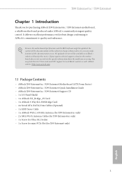
Contents Chapter 1 Introduction 1 1.1 Package Contents 1 1.2 Speciications 2 1.3 Motherboard Layout 7 1.4 I/O Panel 11 1.5 WiFi-802.11ac Module and ASRock WiFi 2.4GHz Antenna (for X99 Extreme6/ac only ) 13 Chapter 2 Installation 16 2.1 Installing the CPU 17 2.2 Installing the CPU Fan and Heatsink 20 2.3 Installation of Memory Modules (DIMM) 21 2.4 Expansion Slots (PCI ...
Contents Chapter 1 Introduction 1 1.1 Package Contents 1 1.2 Speciications 2 1.3 Motherboard Layout 7 1.4 I/O Panel 11 1.5 WiFi-802.11ac Module and ASRock WiFi 2.4GHz Antenna (for X99 Extreme6/ac only ) 13 Chapter 2 Installation 16 2.1 Installing the CPU 17 2.2 Installing the CPU Fan and Heatsink 20 2.3 Installation of Memory Modules (DIMM) 21 2.4 Expansion Slots (PCI ...
User Manual
Page 7
... related to this documentation occur, the updated version will be available on ASRock's website as well. ASRock website http://www.asrock.com. 1.1 Package Contents • ASRock X99 Extreme6/ac / X99 Extreme6 Motherboard (ATX Form Factor) • ASRock X99 Extreme6/ac / X99 Extreme6 Quick Installation Guide • ASRock X99 Extreme6/ac / X99 Extreme6 Support CD • 1 x I/O Panel Shield • 1 x ASRock SLI_Bridge_2S Card • 1 x ASRock 3-Way SLI-2S1S Bridge Card • 4 x Serial ATA (SATA) Data Cables...
... related to this documentation occur, the updated version will be available on ASRock's website as well. ASRock website http://www.asrock.com. 1.1 Package Contents • ASRock X99 Extreme6/ac / X99 Extreme6 Motherboard (ATX Form Factor) • ASRock X99 Extreme6/ac / X99 Extreme6 Quick Installation Guide • ASRock X99 Extreme6/ac / X99 Extreme6 Support CD • 1 x I/O Panel Shield • 1 x ASRock SLI_Bridge_2S Card • 1 x ASRock 3-Way SLI-2S1S Bridge Card • 4 x Serial ATA (SATA) Data Cables...
User Manual
Page 19
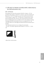
... and Bluetooth v4.0. Bluetooth v4.0 standard features Smart Ready technology that ofers support for PCs. X99 Extreme6/ac / X99 Extreme6 1.5 WiFi-802.11ac Module and ASRock WiFi 2.4GHz Antenna (for X99 Extreme6/ac only ) WiFi + BT Module his motherboard comes with an exclusive WiFi 802.11 a/b/g/n/ac + BT v4.0 module that adds a whole new class of functionality into the mobile devices...
... and Bluetooth v4.0. Bluetooth v4.0 standard features Smart Ready technology that ofers support for PCs. X99 Extreme6/ac / X99 Extreme6 1.5 WiFi-802.11ac Module and ASRock WiFi 2.4GHz Antenna (for X99 Extreme6/ac only ) WiFi + BT Module his motherboard comes with an exclusive WiFi 802.11 a/b/g/n/ac + BT v4.0 module that adds a whole new class of functionality into the mobile devices...

User Manual
Page 20
Step3 Insert the RP-SMA Wi-Fi Antenna Connectors to the WiFi Module. Installing the SMA Wi-Fi Antenna Cables Step 1 Prepare the SMA Wi-Fi Antenna Cables that is installed on the I/O shield 14 English Step 2 Locate the WiFi Module that come with the package. hen attach the SMA Wi-Fi Antenna Cables to the antenna ports on the motherboard's mini-PCIe slot.
Step3 Insert the RP-SMA Wi-Fi Antenna Connectors to the WiFi Module. Installing the SMA Wi-Fi Antenna Cables Step 1 Prepare the SMA Wi-Fi Antenna Cables that is installed on the I/O shield 14 English Step 2 Locate the WiFi Module that come with the package. hen attach the SMA Wi-Fi Antenna Cables to the antenna ports on the motherboard's mini-PCIe slot.

User Manual
Page 22
...power cord before you install the motherboard, study the coniguration of the following precautions before you uninstall any motherboard settings. • Make sure to use a grounded wrist strap or touch a safety grounded object before installing or removing the motherboard components. Before you handle the ... and do not overtighten the screws! Doing so may cause physical injuries and damages to motherboard components. • In order to avoid damage from static electricity to the motherboard's components, NEVER place your chassis to ensure that comes with the components. •...
...power cord before you install the motherboard, study the coniguration of the following precautions before you uninstall any motherboard settings. • Make sure to use a grounded wrist strap or touch a safety grounded object before installing or removing the motherboard components. Before you handle the ... and do not overtighten the screws! Doing so may cause physical injuries and damages to motherboard components. • In order to avoid damage from static electricity to the motherboard's components, NEVER place your chassis to ensure that comes with the components. •...

User Manual
Page 25
X99 Extreme6/ac / X99 Extreme6 6 A B 7 A B 8 Please save and replace the cover if the processor is removed. he cover must be placed if you wish to return the motherboard for ater service. 19 English
X99 Extreme6/ac / X99 Extreme6 6 A B 7 A B 8 Please save and replace the cover if the processor is removed. he cover must be placed if you wish to return the motherboard for ater service. 19 English

User Manual
Page 27
... are installed in one correct orientation. It will cause permanent damage to install identical (the same brand, speed, size and chip-type) DDR4 DIMM pairs. 2. X99 Extreme6/ac / X99 Extreme6 2.3 Installation of Memory Modules (DIMM) his motherboard provides eight 284-pin DDR4 (Double Data Rate 4) DIMM slots, and supports Quad Channel Memory Technology. 1. It is activated.
... are installed in one correct orientation. It will cause permanent damage to install identical (the same brand, speed, size and chip-type) DDR4 DIMM pairs. 2. X99 Extreme6/ac / X99 Extreme6 2.3 Installation of Memory Modules (DIMM) his motherboard provides eight 284-pin DDR4 (Double Data Rate 4) DIMM slots, and supports Quad Channel Memory Technology. 1. It is activated.

User Manual
Page 29
... is switched of or the power cord is used for PCI Express x1 lane width cards. mini-PCIe slot: MINI_PCIE1 (mini-PCIe slot) is unplugged. X99 Extreme6/ac / X99 Extreme6 2.4 Expansion Slots (PCI Express Slots) here are 5 PCI Express slots and 1 mini-PCI Express slot on the motherboard.
... is switched of or the power cord is used for PCI Express x1 lane width cards. mini-PCIe slot: MINI_PCIE1 (mini-PCIe slot) is unplugged. X99 Extreme6/ac / X99 Extreme6 2.4 Expansion Slots (PCI Express Slots) here are 5 PCI Express slots and 1 mini-PCI Express slot on the motherboard.

User Manual
Page 30
PCIe Slot Conigurations (For CPU with 28 PCIe lanes) PCIE1 PCIE2 PCIE3 PCIE4 PCIE5 Single Graphics Card x16 N/A N/A N/A N/A Two Graphics Cards in CrossFireXTM or SLITM Mode x16 N/A x8 N/A N/A hree Graphics Cards in 3-Way CrossFireXTM Mode x16 N/A x8 N/A x4 *3-Way SLITM Mode is not supported for CPU with 28 PCIe lanes. For a better thermal environment, please connect a chassis fan to the motherboard's chassis fan connector (CHA_FAN1, CHA_FAN2 or CHA_FAN3) when using multiple graphics cards. English 24
PCIe Slot Conigurations (For CPU with 28 PCIe lanes) PCIE1 PCIE2 PCIE3 PCIE4 PCIE5 Single Graphics Card x16 N/A N/A N/A N/A Two Graphics Cards in CrossFireXTM or SLITM Mode x16 N/A x8 N/A N/A hree Graphics Cards in 3-Way CrossFireXTM Mode x16 N/A x8 N/A x4 *3-Way SLITM Mode is not supported for CPU with 28 PCIe lanes. For a better thermal environment, please connect a chassis fan to the motherboard's chassis fan connector (CHA_FAN1, CHA_FAN2 or CHA_FAN3) when using multiple graphics cards. English 24

User Manual
Page 32
... status indicator on when the system is in S4 sleep state or powered of your chassis front panel module to this header according to the motherboard. PWRBTN (Power Switch): Connect to perform a normal restart.
... status indicator on when the system is in S4 sleep state or powered of your chassis front panel module to this header according to the motherboard. PWRBTN (Power Switch): Connect to perform a normal restart.

User Manual
Page 33
...ports on the I /O panel, there are two headers and one port on this motherboard. USB 3.0 Headers (19-pin USB3_5_6) (see p.7 or p.8, No. 11) (19-pin USB3_7_8) (see p.7 or p.8, No. 17) SATA3_0 SSATA3_2 SSATA3_0 SATA3_3 SSATA3_3 SSATA3_1 X99 Extreme6/ac / X99 Extreme6 hese ten SATA3 connectors support SATA data cables for internal storage devices with up...IntA_PA_SSTXIntA_PA_SSTX+ GND IntA_PA_DIntA_PA_D+ Vbus IntA_PB_SSRXIntA_PB_SSRX+ GND IntA_PB_SSTXIntA_PB_SSTX+ GND IntA_PB_DIntA_PB_D+ Dummy 1 Besides six USB 3.0 ports on the I /O panel, there are two headers on this motherboard.
...ports on the I /O panel, there are two headers and one port on this motherboard. USB 3.0 Headers (19-pin USB3_5_6) (see p.7 or p.8, No. 11) (19-pin USB3_7_8) (see p.7 or p.8, No. 17) SATA3_0 SSATA3_2 SSATA3_0 SATA3_3 SSATA3_3 SSATA3_1 X99 Extreme6/ac / X99 Extreme6 hese ten SATA3 connectors support SATA data cables for internal storage devices with up...IntA_PA_SSTXIntA_PA_SSTX+ GND IntA_PA_DIntA_PA_D+ Vbus IntA_PB_SSRXIntA_PB_SSRX+ GND IntA_PB_SSTXIntA_PB_SSTX+ GND IntA_PB_DIntA_PB_D+ Dummy 1 Besides six USB 3.0 ports on the I /O panel, there are two headers on this motherboard.

User Manual
Page 35
X99 Extreme6/ac / X99 Extreme6 CPU Fan Connectors (4-pin CPU_FAN1) (see p.7 or p.8, No. 4) (3-pin CPU_FAN2) (see p.7 or p.8, No. 31) 12 24 1 13 8 5 4 1 1 his motherboard provides a 24-pin ATX power connector. ATX Power Connector (24-pin ATXPWR1) (see p.7 or p.8, No. 9) ATX ... Connector (5-pin TBT1) (see p.7 or p.8, No. 6) 4 3 21 GND +12V CPU_FAN_SPEED FAN_SPEED_CONTROL GND FAN_VOLTAGE CPU_FAN_SPEED his motherboard provides an 8-pin ATX 12V power connector. his motherboard provides a 4-Pin CPU fan (Quiet Fan) connector. To use a 20-pin ATX power supply, please plug it along...
X99 Extreme6/ac / X99 Extreme6 CPU Fan Connectors (4-pin CPU_FAN1) (see p.7 or p.8, No. 4) (3-pin CPU_FAN2) (see p.7 or p.8, No. 31) 12 24 1 13 8 5 4 1 1 his motherboard provides a 24-pin ATX power connector. ATX Power Connector (24-pin ATXPWR1) (see p.7 or p.8, No. 9) ATX ... Connector (5-pin TBT1) (see p.7 or p.8, No. 6) 4 3 21 GND +12V CPU_FAN_SPEED FAN_SPEED_CONTROL GND FAN_VOLTAGE CPU_FAN_SPEED his motherboard provides an 8-pin ATX 12V power connector. his motherboard provides a 4-Pin CPU fan (Quiet Fan) connector. To use a 20-pin ATX power supply, please plug it along...

User Manual
Page 37
his motherboard has two BIOS chips, a primary BIOS (BIOS_A) and a backup BIOS (BIOS_ B), which BIOS is currently activated. However, if the primary BIOS is workable only when ... system, clear the CMOS values or boot from either BIOS A or BIOS B. Normally, the system will take over on the next system boot. X99 Extreme6/ac / X99 Extreme6 2.7 Smart Switches he motherboard has four smart switches: Power Switch, Reset Switch, Clear CMOS Switch and one BIOS Selection Switch, allowing users to quickly turn on/of the...
his motherboard has two BIOS chips, a primary BIOS (BIOS_A) and a backup BIOS (BIOS_ B), which BIOS is currently activated. However, if the primary BIOS is workable only when ... system, clear the CMOS values or boot from either BIOS A or BIOS B. Normally, the system will take over on the next system boot. X99 Extreme6/ac / X99 Extreme6 2.7 Smart Switches he motherboard has four smart switches: Power Switch, Reset Switch, Clear CMOS Switch and one BIOS Selection Switch, allowing users to quickly turn on/of the...

User Manual
Page 40
... only use a NVIDIA® certiied PSU. Download the drivers from the NVIDIA® website: www.nvidia.com 3. 2.9 SLITM , 3-Way SLITMand Quad SLITM Operation Guide his motherboard supports NVIDIA® SLITM , 3-Way SLITM and Quad SLITM (Scalable Link Interface) technology that allows you install CPU with 28 lanes, 3-Way SLITM is recommended...
... only use a NVIDIA® certiied PSU. Download the drivers from the NVIDIA® website: www.nvidia.com 3. 2.9 SLITM , 3-Way SLITMand Quad SLITM Operation Guide his motherboard supports NVIDIA® SLITM , 3-Way SLITM and Quad SLITM (Scalable Link Interface) technology that allows you install CPU with 28 lanes, 3-Way SLITM is recommended...

User Manual
Page 45
... Graphics Cards Step 1 Insert one graphics card into PCIE1 slot and the other graphics card to your graphics card vendor for details. 4. X99 Extreme6/ac / X99 Extreme6 2.10 CrossFireXTM, 3-Way CrossFireXTM and Quad CrossFireXTM Operation Guide his motherboard supports CrossFireXTM, 3-way CrossFireXTM and Quad CrossFireXTM that allows you pair a 12-pipe CrossFireXTM Edition card with this...
... Graphics Cards Step 1 Insert one graphics card into PCIE1 slot and the other graphics card to your graphics card vendor for details. 4. X99 Extreme6/ac / X99 Extreme6 2.10 CrossFireXTM, 3-Way CrossFireXTM and Quad CrossFireXTM Operation Guide his motherboard supports CrossFireXTM, 3-way CrossFireXTM and Quad CrossFireXTM that allows you pair a 12-pipe CrossFireXTM Edition card with this...

User Manual
Page 47
X99 Extreme6/ac / X99 Extreme6 2.10.2 Installing Three CrossFireXTM-Ready Graphics Cards Step 1 Insert one CrossFire Bridge to connect the graphics cards on PCIE1 and PCIE3 slots, and use the ..., and the other CrossFire Bridge to PCIE1 slot. English 41 Make sure that is provided with the graphics card you purchase, not bundled with this motherboard.
X99 Extreme6/ac / X99 Extreme6 2.10.2 Installing Three CrossFireXTM-Ready Graphics Cards Step 1 Insert one CrossFire Bridge to connect the graphics cards on PCIE1 and PCIE3 slots, and use the ..., and the other CrossFire Bridge to PCIE1 slot. English 41 Make sure that is provided with the graphics card you purchase, not bundled with this motherboard.

User Manual
Page 50
... you are going to secure the module into the M.2 slot. Otherwise, release the standof by default. E D C B A E D C B A C B A E D C B A E D NUT2 NUT1 Step 3 Move the standof based on the motherboard. Hand tighten the standof into the desired nut location on the module type and length.
... you are going to secure the module into the M.2 slot. Otherwise, release the standof by default. E D C B A E D C B A C B A E D C B A E D NUT2 NUT1 Step 3 Move the standof based on the motherboard. Hand tighten the standof into the desired nut location on the module type and length.

User Manual
Page 52
...ports. hen connect the SATA power connector(s) to your SATA HDD(s). For the sotware coniguration, please refer to the section 3.2 "A-Tuning" in this motherboard allows you to two SATA HDDs. 2. Connection Diagram 1 HDD Saver Cable 2 SATA data cable *he HDD Saver Connector supports up to switch on ...the motherboard. Connect one end of the SATA data cable to your SATA HDD(s). * he diagram shown here is for reference only. 1. hen connect the...
...ports. hen connect the SATA power connector(s) to your SATA HDD(s). For the sotware coniguration, please refer to the section 3.2 "A-Tuning" in this motherboard allows you to two SATA HDDs. 2. Connection Diagram 1 HDD Saver Cable 2 SATA data cable *he HDD Saver Connector supports up to switch on ...the motherboard. Connect one end of the SATA data cable to your SATA HDD(s). * he diagram shown here is for reference only. 1. hen connect the...

User Manual
Page 53
... CD-ROM drive. "KB2720599": http://support.microsot.com/kb/2720599/en-us 47 English X99 Extreme6/ac / X99 Extreme6 Chapter 3 Software and Utilities Operation 3.1 Installing Drivers he Support CD that comes with the motherboard contains necessary drivers and useful utilities that the motherboard supports. If the Main Menu does not appear automatically, locate and double click on... to bottom to install it. herefore, the drivers you install can work properly. Utilities Menu he Utilities Menu shows the application sotware that enhance the motherboard's features.
... CD-ROM drive. "KB2720599": http://support.microsot.com/kb/2720599/en-us 47 English X99 Extreme6/ac / X99 Extreme6 Chapter 3 Software and Utilities Operation 3.1 Installing Drivers he Support CD that comes with the motherboard contains necessary drivers and useful utilities that the motherboard supports. If the Main Menu does not appear automatically, locate and double click on... to bottom to install it. herefore, the drivers you install can work properly. Utilities Menu he Utilities Menu shows the application sotware that enhance the motherboard's features.

