
User Manual
Page 4
...1.3 Motherboard Layout 7 1.4 I/O Panel 11 1.5 WiFi-802.11ac Module and ASRock WiFi 2.4GHz Antenna (for X99 Extreme6/ac only ) 13 Chapter 2 Installation 16 2.1 Installing the CPU 17 2.2 Installing the CPU Fan and Heatsink 20 2.3 Installation of Memory Modules (DIMM) 21 2.4 Expansion Slots (PCI Express Slots) 23 2.5 Jumpers Setup 25 2.6 Onboard Headers and Connectors 26 2.7 Smart Switches 31 2.8 Dr. Debug 32 2.9 SLITM , 3-Way SLITMand Quad SLITM Operation Guide 34 2.9.1 Installing Two SLITM-Ready Graphics Cards 34 2.9.2 Installing Three SLITM-Ready Graphics Cards 36...
...1.3 Motherboard Layout 7 1.4 I/O Panel 11 1.5 WiFi-802.11ac Module and ASRock WiFi 2.4GHz Antenna (for X99 Extreme6/ac only ) 13 Chapter 2 Installation 16 2.1 Installing the CPU 17 2.2 Installing the CPU Fan and Heatsink 20 2.3 Installation of Memory Modules (DIMM) 21 2.4 Expansion Slots (PCI Express Slots) 23 2.5 Jumpers Setup 25 2.6 Onboard Headers and Connectors 26 2.7 Smart Switches 31 2.8 Dr. Debug 32 2.9 SLITM , 3-Way SLITMand Quad SLITM Operation Guide 34 2.9.1 Installing Two SLITM-Ready Graphics Cards 34 2.9.2 Installing Three SLITM-Ready Graphics Cards 36...
User Manual
Page 7
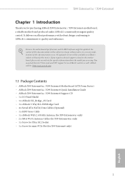
...) • ASRock X99 Extreme6/ac / X99 Extreme6 Quick Installation Guide • ASRock X99 Extreme6/ac / X99 Extreme6 Support CD • 1 x I/O Panel Shield • 1 x ASRock SLI_Bridge_2S Card • 1 x ASRock 3-Way SLI-2S1S Bridge Card • 4 x Serial ATA (SATA) Data Cables (Optional) • 1 x HDD Saver Cable • 1 x ASRock WiFi 2.4/5GHz Antenna (for X99 Extreme6/ac only) • 2 x SMA Wi-Fi Antenna Cables (for X99 Extreme6/ac only) • 1 x Screw for Ultra M.2 Socket • 1 x Screw for mini-PCIe Slot (for speciic information about the model you are using. It delivers...
...) • ASRock X99 Extreme6/ac / X99 Extreme6 Quick Installation Guide • ASRock X99 Extreme6/ac / X99 Extreme6 Support CD • 1 x I/O Panel Shield • 1 x ASRock SLI_Bridge_2S Card • 1 x ASRock 3-Way SLI-2S1S Bridge Card • 4 x Serial ATA (SATA) Data Cables (Optional) • 1 x HDD Saver Cable • 1 x ASRock WiFi 2.4/5GHz Antenna (for X99 Extreme6/ac only) • 2 x SMA Wi-Fi Antenna Cables (for X99 Extreme6/ac only) • 1 x Screw for Ultra M.2 Socket • 1 x Screw for mini-PCIe Slot (for speciic information about the model you are using. It delivers...
User Manual
Page 8
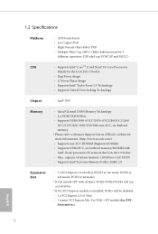
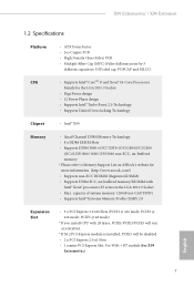
... 2011-3 Socket • Digi Power design • 12 Power Phase design • Supports Intel® Turbo Boost 2.0 Technology • Supports Untied Overclocking Technology Chipset • Intel® X99 Memory • Quad Channel DDR4 Memory Technology • 8 x DDR4 DIMM Slots • Supports DDR4 3000+(OC)*/2933+(OC)/2800(OC)/2400 (OC)/2133/1866/ 1600/1333/1066 non-ECC, un-bufered memory * Please refer to Memory Support List on ASRock's website for X99 Extreme6/ac) English...
... 2011-3 Socket • Digi Power design • 12 Power Phase design • Supports Intel® Turbo Boost 2.0 Technology • Supports Untied Overclocking Technology Chipset • Intel® X99 Memory • Quad Channel DDR4 Memory Technology • 8 x DDR4 DIMM Slots • Supports DDR4 3000+(OC)*/2933+(OC)/2800(OC)/2400 (OC)/2133/1866/ 1600/1333/1066 non-ECC, un-bufered memory * Please refer to Memory Support List on ASRock's website for X99 Extreme6/ac) English...

User Manual
Page 10
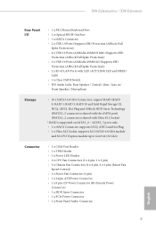
...; 2 x USB 3.0 Ports (ASMedia ASM1042) (Supports ESD Protection (ASRock Full Spike Protection)) • 2 x RJ-45 LAN Ports with LED (ACT/LINK LED and SPEED LED) • 1 x Clear CMOS Switch • HD Audio Jacks: Rear Speaker / Central / Bass / Line in / Front Speaker / Microphone Storage • 10 x SATA3 6.0 Gb/s Connectors, support RAID (RAID 0, RAID 1, RAID 5, RAID 10 and Intel Rapid Storage 13), NCQ, AHCI, Hot Plug and ASRock HDD Saver Technology (SSATA3_3 connector is shared with the eSATA port) (SSATA3_2 connector is shared with Ultra M.2 Socket) * RAID is supported...
...; 2 x USB 3.0 Ports (ASMedia ASM1042) (Supports ESD Protection (ASRock Full Spike Protection)) • 2 x RJ-45 LAN Ports with LED (ACT/LINK LED and SPEED LED) • 1 x Clear CMOS Switch • HD Audio Jacks: Rear Speaker / Central / Bass / Line in / Front Speaker / Microphone Storage • 10 x SATA3 6.0 Gb/s Connectors, support RAID (RAID 0, RAID 1, RAID 5, RAID 10 and Intel Rapid Storage 13), NCQ, AHCI, Hot Plug and ASRock HDD Saver Technology (SSATA3_3 connector is shared with the eSATA port) (SSATA3_2 connector is shared with Ultra M.2 Socket) * RAID is supported...

User Manual
Page 11
...; 2 x USB 3.0 Headers (Support 4 USB 3.0 ports) (Supports ESD Protection (ASRock Full Spike Protection)) • 1 x Dr. Debug with LED • 1 x Power Switch with LED • 1 x Reset Switch with LED • 1 x BIOS Selection Switch • 2 x 128Mb AMI UEFI Legal BIOS with multilingual GUI support (1 x Main BIOS and 1 x Backup BIOS) • Supports Secure Backup UEFI Technology • ACPI 1.1 Compliant wake up events • SMBIOS 2.3.1 Support • CPU, DRAM, PCH 1.05V, PCH 1.5V, VPPM Voltage Multi- adjustment • CPU/Chassis temperature sensing • CPU/Chassis/Power Fan...
...; 2 x USB 3.0 Headers (Support 4 USB 3.0 ports) (Supports ESD Protection (ASRock Full Spike Protection)) • 1 x Dr. Debug with LED • 1 x Power Switch with LED • 1 x Reset Switch with LED • 1 x BIOS Selection Switch • 2 x 128Mb AMI UEFI Legal BIOS with multilingual GUI support (1 x Main BIOS and 1 x Backup BIOS) • Supports Secure Backup UEFI Technology • ACPI 1.1 Compliant wake up events • SMBIOS 2.3.1 Support • CPU, DRAM, PCH 1.05V, PCH 1.5V, VPPM Voltage Multi- adjustment • CPU/Chassis temperature sensing • CPU/Chassis/Power Fan...

User Manual
Page 15
... Connectors (SATA3_1_4) 17 SATA3 Connectors (SATA3_2_5) 18 Power LED Header (PLED1) 19 Chassis Speaker Header (SPEAKER1) 20 System Panel Header (PANEL1) 21 Power Switch (PWRBTN1) 22 HDD Saver Connector (SATA_PWR_1) 23 Reset Switch (RSTBTN1) 24 Chassis Fan Connector (CHA_FAN2) 25 Chassis Fan Connector (CHA_FAN1) 26 USB 2.0 Header (USB3_4) 27 USB 2.0 Header (USB5_6) 28 BIOS Selection Switch (BIOS_SEL1) 29 Clear CMOS Jumper (CLRCMOS1) 30 COM Port Header (COM1) 31 hunderbolt AIC Connector (TBT1) 32 TPM Header (TPMS1) 33 Front Panel Audio Header (HD_AUDIO1) 9 English X99 Extreme6/ac / X99 Extreme6...
... Connectors (SATA3_1_4) 17 SATA3 Connectors (SATA3_2_5) 18 Power LED Header (PLED1) 19 Chassis Speaker Header (SPEAKER1) 20 System Panel Header (PANEL1) 21 Power Switch (PWRBTN1) 22 HDD Saver Connector (SATA_PWR_1) 23 Reset Switch (RSTBTN1) 24 Chassis Fan Connector (CHA_FAN2) 25 Chassis Fan Connector (CHA_FAN1) 26 USB 2.0 Header (USB3_4) 27 USB 2.0 Header (USB5_6) 28 BIOS Selection Switch (BIOS_SEL1) 29 Clear CMOS Jumper (CLRCMOS1) 30 COM Port Header (COM1) 31 hunderbolt AIC Connector (TBT1) 32 TPM Header (TPMS1) 33 Front Panel Audio Header (HD_AUDIO1) 9 English X99 Extreme6/ac / X99 Extreme6...

User Manual
Page 35
... his motherboard provides a 4-Pin CPU fan (Quiet Fan) connector. his motherboard provides a 24-pin ATX power connector. Please connect the HDD Saver Cable to this connector to this connector via the GPIO cable. 29 English Please connect a 4 pin molex power cable to manage the power state of HDD. To use a 4-pin ATX power supply, please plug it along Pin 1 and Pin 13. If you plan to this connector when more than three graphics cards are installed. To use a 20-pin ATX power supply, please plug it to Pin 1-3. X99 Extreme6/ac / X99 Extreme6 CPU Fan Connectors (4-pin...
... his motherboard provides a 4-Pin CPU fan (Quiet Fan) connector. his motherboard provides a 24-pin ATX power connector. Please connect the HDD Saver Cable to this connector to this connector via the GPIO cable. 29 English Please connect a 4 pin molex power cable to manage the power state of HDD. To use a 4-pin ATX power supply, please plug it along Pin 1 and Pin 13. If you plan to this connector when more than three graphics cards are installed. To use a 20-pin ATX power supply, please plug it to Pin 1-3. X99 Extreme6/ac / X99 Extreme6 CPU Fan Connectors (4-pin...

User Manual
Page 38
... VGA card, and remove other devices. Please re-install IDE and SATA devices. Code Description 00 Please check if the CPU is used to provide code information, which makes troubleshooting even easier. A7 Problem related to memory. Please re-install the CPU and memory. If the problem still exists, please install only one memory module or try using other slots. 2.8 Dr. Debug Dr. Debug is installed correctly and then clear CMOS. 0d Problem related to memory, VGA card or other USB, PCI devices...
... VGA card, and remove other devices. Please re-install IDE and SATA devices. Code Description 00 Please check if the CPU is used to provide code information, which makes troubleshooting even easier. A7 Problem related to memory. Please re-install the CPU and memory. If the problem still exists, please install only one memory module or try using other slots. 2.8 Dr. Debug Dr. Debug is installed correctly and then clear CMOS. 0d Problem related to memory, VGA card or other USB, PCI devices...

User Manual
Page 45
... enable CrossFireXTM. X99 Extreme6/ac / X99 Extreme6 2.10 CrossFireXTM, 3-Way CrossFireXTM and Quad CrossFireXTM Operation Guide his motherboard supports CrossFireXTM, 3-way CrossFireXTM and Quad CrossFireXTM that your power supply unit (PSU) can provide at least the minimum power your system requires. Download the drivers from the AMD's website: www.amd.com 3. If you to install up to use identical CrossFireXTM-ready graphics cards that your graphics card vendor for details. 4. Diferent CrossFireXTM cards...
... enable CrossFireXTM. X99 Extreme6/ac / X99 Extreme6 2.10 CrossFireXTM, 3-Way CrossFireXTM and Quad CrossFireXTM Operation Guide his motherboard supports CrossFireXTM, 3-way CrossFireXTM and Quad CrossFireXTM that your power supply unit (PSU) can provide at least the minimum power your system requires. Download the drivers from the AMD's website: www.amd.com 3. If you to install up to use identical CrossFireXTM-ready graphics cards that your graphics card vendor for details. 4. Diferent CrossFireXTM cards...

User Manual
Page 48
... your graphics card and click Apply. AMD Catalyst Control Center Step 4 Double-click the AMD Catalyst Control Center icon in your computer and boot into OS. he Catalyst Uninstaller is an optional download. English 42 Step 2 Remove the AMD drivers if you have any previously installed Catalyst drivers prior to uninstall any VGA drivers installed in the Windows® system tray. We recommend using this utility to installation. 2.10.3 Driver Installation and Setup Step 1 Power...
... your graphics card and click Apply. AMD Catalyst Control Center Step 4 Double-click the AMD Catalyst Control Center icon in your computer and boot into OS. he Catalyst Uninstaller is an optional download. English 42 Step 2 Remove the AMD drivers if you have any previously installed Catalyst drivers prior to uninstall any VGA drivers installed in the Windows® system tray. We recommend using this utility to installation. 2.10.3 Driver Installation and Setup Step 1 Power...

User Manual
Page 53
... install can work properly. Please click Install All or follow the installation wizard to install those required drivers. X99 Extreme6/ac / X99 Extreme6 Chapter 3 Software and Utilities Operation 3.1 Installing Drivers he Support CD that comes with the motherboard contains necessary drivers and useful utilities that the motherboard supports. he Utilities Menu shows the application sotware that enhance the motherboard's features. Utilities Menu he CD automatically displays the Main Menu if "AUTORUN" is enabled in the Support CD to your system will be auto...
... install can work properly. Please click Install All or follow the installation wizard to install those required drivers. X99 Extreme6/ac / X99 Extreme6 Chapter 3 Software and Utilities Operation 3.1 Installing Drivers he Support CD that comes with the motherboard contains necessary drivers and useful utilities that the motherboard supports. he Utilities Menu shows the application sotware that enhance the motherboard's features. Utilities Menu he CD automatically displays the Main Menu if "AUTORUN" is enabled in the Support CD to your system will be auto...

User Manual
Page 95
... a power failure. Deep Sleep Conigure deep sleep mode for X99 Extreme6/ac only) Enable/disable the WiFi module's connectivity. 89 English If [Power On] is selected, the system will also automatically switch of when the power recovers. Front Panel Enable/disable front panel HD audio. Restore on . It will start to enable onboard HD audio and automatically disable it when a sound card is shut down. X99 Extreme6/ac / X99 Extreme6 PCI-E ASPM Support his option enables/disables the ASPM support for all CPU downstream devices PCH PCI-E ASPM Support his option enables/disables the...
... a power failure. Deep Sleep Conigure deep sleep mode for X99 Extreme6/ac only) Enable/disable the WiFi module's connectivity. 89 English If [Power On] is selected, the system will also automatically switch of when the power recovers. Front Panel Enable/disable front panel HD audio. Restore on . It will start to enable onboard HD audio and automatically disable it when a sound card is shut down. X99 Extreme6/ac / X99 Extreme6 PCI-E ASPM Support his option enables/disables the ASPM support for all CPU downstream devices PCH PCI-E ASPM Support his option enables/disables the...

User Manual
Page 99
...X99 Extreme6/ac / X99 Extreme6 USB Controller Enable or disable all the USB ports. Select UEFI Setup Only to keep the USB 3.0 driver enabled ater rebooting (USB 3.0 is disabled in BIOS). Set [Enabled] to support USB devices under the UEFI setup and Windows/Linux operating systems only. 93 English Intel USB 3.0 Mode Select Intel® USB 3.0 controller mode. Set [Smart Auto] to keep the USB 3.0 driver enabled (Must install driver to disable the USB 3.0 ports. Set [Disabled] to use USB devices under Windows® 7). Legacy USB 3.0 Support Enable or disable Legacy OS Support...
...X99 Extreme6/ac / X99 Extreme6 USB Controller Enable or disable all the USB ports. Select UEFI Setup Only to keep the USB 3.0 driver enabled ater rebooting (USB 3.0 is disabled in BIOS). Set [Enabled] to support USB devices under the UEFI setup and Windows/Linux operating systems only. 93 English Intel USB 3.0 Mode Select Intel® USB 3.0 controller mode. Set [Smart Auto] to keep the USB 3.0 driver enabled (Must install driver to disable the USB 3.0 ports. Set [Disabled] to use USB devices under Windows® 7). Legacy USB 3.0 Support Enable or disable Legacy OS Support...
User Manual
Page 103
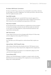
... plug in RAID mode. Secure Backup UEFI Whenever one of your OS. Easy Driver Installer For users that don't have an optical disk drive to install the drivers from our servers for any changes of the ROM images are having trouble with your USB storage device. Please setup network coniguration before using Internet Flash. *For BIOS backup and recovery purpose, it is a handy tool in your USB storage device and run Instant Flash to your UEFI. X99 Extreme6/ac / X99 Extreme6 Re-detect SATA Power Connection...
... plug in RAID mode. Secure Backup UEFI Whenever one of your OS. Easy Driver Installer For users that don't have an optical disk drive to install the drivers from our servers for any changes of the ROM images are having trouble with your USB storage device. Please setup network coniguration before using Internet Flash. *For BIOS backup and recovery purpose, it is a handy tool in your USB storage device and run Instant Flash to your UEFI. X99 Extreme6/ac / X99 Extreme6 Re-detect SATA Power Connection...

User Manual
Page 104
Internet Setting Enable or disable sound efects in the setup utility. UEFI Download Server Select a server to save your settings as user default. Load User Default Load previously saved user defaults. 98 English Save User Default Type a proile name and press enter to download the UEFI irmware. Network Coniguration Use this to conigure internet connection settings for Internet Flash.
Internet Setting Enable or disable sound efects in the setup utility. UEFI Download Server Select a server to save your settings as user default. Load User Default Load previously saved user defaults. 98 English Save User Default Type a proile name and press enter to download the UEFI irmware. Network Coniguration Use this to conigure internet connection settings for Internet Flash.

Quick Installation Guide
Page 5
... 18 Power LED Header (PLED1) 19 Chassis Speaker Header (SPEAKER1) 20 System Panel Header (PANEL1) 21 Power Switch (PWRBTN1) 22 HDD Saver Connector (SATA_PWR_1) 23 Reset Switch (RSTBTN1) 24 Chassis Fan Connector (CHA_FAN2) 25 Chassis Fan Connector (CHA_FAN1) 26 USB 2.0 Header (USB3_4) 27 USB 2.0 Header (USB5_6) 28 BIOS Selection Switch (BIOS_SEL1) 29 Clear CMOS Jumper (CLRCMOS1) 30 COM Port Header (COM1) 31 hunderbolt AIC Connector (TBT1) 32 TPM Header (TPMS1) 33 Front Panel Audio Header (HD_AUDIO1) 34 PCIe Power Connector (PCIE_PWR1) 35 Power Fan Connector (PWR_FAN1) 3 English X99 Extreme6/ac...
... 18 Power LED Header (PLED1) 19 Chassis Speaker Header (SPEAKER1) 20 System Panel Header (PANEL1) 21 Power Switch (PWRBTN1) 22 HDD Saver Connector (SATA_PWR_1) 23 Reset Switch (RSTBTN1) 24 Chassis Fan Connector (CHA_FAN2) 25 Chassis Fan Connector (CHA_FAN1) 26 USB 2.0 Header (USB3_4) 27 USB 2.0 Header (USB5_6) 28 BIOS Selection Switch (BIOS_SEL1) 29 Clear CMOS Jumper (CLRCMOS1) 30 COM Port Header (COM1) 31 hunderbolt AIC Connector (TBT1) 32 TPM Header (TPMS1) 33 Front Panel Audio Header (HD_AUDIO1) 34 PCIe Power Connector (PCIE_PWR1) 35 Power Fan Connector (PWR_FAN1) 3 English X99 Extreme6/ac...
Quick Installation Guide
Page 9
...; X99 Memory • Quad Channel DDR4 Memory Technology • 8 x DDR4 DIMM Slots • Supports DDR4 3000+(OC)*/2933+(OC)/2800(OC)/2400 (OC)/2133/1866/ 1600/1333/1066 non-ECC, un-bufered memory * Please refer to Memory Support List on ASRock's website for X99 Extreme6/ac) English 7 PCIE5 @ x8 mode) * If you install CPU with 28 lanes, PCIE1/PCIE3/PCIE5 will run at x16/x8/x4. * If M.2 PCI Express module...
...; X99 Memory • Quad Channel DDR4 Memory Technology • 8 x DDR4 DIMM Slots • Supports DDR4 3000+(OC)*/2933+(OC)/2800(OC)/2400 (OC)/2133/1866/ 1600/1333/1066 non-ECC, un-bufered memory * Please refer to Memory Support List on ASRock's website for X99 Extreme6/ac) English 7 PCIE5 @ x8 mode) * If you install CPU with 28 lanes, PCIE1/PCIE3/PCIE5 will run at x16/x8/x4. * If M.2 PCI Express module...
Quick Installation Guide
Page 11
...; 2 x USB 3.0 Ports (ASMedia ASM1042) (Supports ESD Protection (ASRock Full Spike Protection)) • 2 x RJ-45 LAN Ports with LED (ACT/LINK LED and SPEED LED) • 1 x Clear CMOS Switch • HD Audio Jacks: Rear Speaker / Central / Bass / Line in / Front Speaker / Microphone Storage • 10 x SATA3 6.0 Gb/s Connectors, support RAID (RAID 0, RAID 1, RAID 5, RAID 10 and Intel Rapid Storage 13), NCQ, AHCI, Hot Plug and ASRock HDD Saver Technology (SSATA3_3 connector is shared with the eSATA port) (SSATA3_2 connector is shared with Ultra M.2 Socket) * RAID is supported...
...; 2 x USB 3.0 Ports (ASMedia ASM1042) (Supports ESD Protection (ASRock Full Spike Protection)) • 2 x RJ-45 LAN Ports with LED (ACT/LINK LED and SPEED LED) • 1 x Clear CMOS Switch • HD Audio Jacks: Rear Speaker / Central / Bass / Line in / Front Speaker / Microphone Storage • 10 x SATA3 6.0 Gb/s Connectors, support RAID (RAID 0, RAID 1, RAID 5, RAID 10 and Intel Rapid Storage 13), NCQ, AHCI, Hot Plug and ASRock HDD Saver Technology (SSATA3_3 connector is shared with the eSATA port) (SSATA3_2 connector is shared with Ultra M.2 Socket) * RAID is supported...

Quick Installation Guide
Page 29
...Pin 1 and Pin 13. To use a 20-pin ATX power supply, please plug it along Pin 1 and Pin 5. X99 Extreme6/ac / X99 Extreme6 CPU Fan Connectors (4-pin CPU_FAN1) (see p.1 or p.2, No. 4) (3-pin CPU_FAN2) (see p.1 or p.2, No. 31) 12 24 1 13 8 5 4 1 1 his motherboard provides a 4-Pin CPU fan (Quiet Fan) connector. Please connect a hunderbolt™ add-in card (AIC) to this connector when more than three graphics cards are installed. ATX Power Connector (24-pin ATXPWR1) (see p.1 or p.2, No. 9) ATX 12V Power Connector (8-pin ATX12V1) (see p.1 or p.2, No. 3) PCIe Power Connector...
...Pin 1 and Pin 13. To use a 20-pin ATX power supply, please plug it along Pin 1 and Pin 5. X99 Extreme6/ac / X99 Extreme6 CPU Fan Connectors (4-pin CPU_FAN1) (see p.1 or p.2, No. 4) (3-pin CPU_FAN2) (see p.1 or p.2, No. 31) 12 24 1 13 8 5 4 1 1 his motherboard provides a 4-Pin CPU fan (Quiet Fan) connector. Please connect a hunderbolt™ add-in card (AIC) to this connector when more than three graphics cards are installed. ATX Power Connector (24-pin ATXPWR1) (see p.1 or p.2, No. 9) ATX 12V Power Connector (8-pin ATX12V1) (see p.1 or p.2, No. 3) PCIe Power Connector...

Quick Installation Guide
Page 32
... re-install the memory and CPU. Please see the diagrams below for reading the Dr. Debug codes. Please press reset or clear CMOS. 92 - 99 Problem related to IDE or SATA devices. If the problem still exists, please clear CMOS and try removing all PCI-E devices or try using other memory modules. 55 he Memory could not be detected. If the problem still exists, please install only one memory module or try using other USB, PCI devices. 01...
... re-install the memory and CPU. Please see the diagrams below for reading the Dr. Debug codes. Please press reset or clear CMOS. 92 - 99 Problem related to IDE or SATA devices. If the problem still exists, please clear CMOS and try removing all PCI-E devices or try using other memory modules. 55 he Memory could not be detected. If the problem still exists, please install only one memory module or try using other USB, PCI devices. 01...


