

User Manual
Page 5
... (NGFF) Module Installation Guide 39 2.12 HDD Saver Cable Installation Guide 42 2.13 ASRock USB 3.1 Card/A+A Installation Guide 43 Chapter 3 Software and Utilities Operation 45 3.1 Installing Drivers 45 3.2 A-Tuning 46 3.3 ASRock APP Shop 52 3.3.1 UI Overview 52 3.3.2 Apps 53 3.3.3 BIOS & Drivers 56 3.3.4 Setting 57 3.4 Start8 58 Chapter 4 UEFI SETUP UTILITY 61 4.1 Introduction 61...
... (NGFF) Module Installation Guide 39 2.12 HDD Saver Cable Installation Guide 42 2.13 ASRock USB 3.1 Card/A+A Installation Guide 43 Chapter 3 Software and Utilities Operation 45 3.1 Installing Drivers 45 3.2 A-Tuning 46 3.3 ASRock APP Shop 52 3.3.1 UI Overview 52 3.3.2 Apps 53 3.3.3 BIOS & Drivers 56 3.3.4 Setting 57 3.4 Start8 58 Chapter 4 UEFI SETUP UTILITY 61 4.1 Introduction 61...
User Manual
Page 7
...) • 1 x HDD Saver Cable • 1 x Screw for Ultra M.2 Socket • 1 x Screw for purchasing ASRock X99 Extreme6/3.1 motherboard, a reliable motherboard produced under ASRock's consistently stringent quality control. Because the motherboard speciications and the BIOS sotware might be available on ASRock's website as well. X99 Extreme6/3.1 Chapter 1 Introduction hank you are using. Chapter 4 contains the coniguration guide of the sotware...
...) • 1 x HDD Saver Cable • 1 x Screw for Ultra M.2 Socket • 1 x Screw for purchasing ASRock X99 Extreme6/3.1 motherboard, a reliable motherboard produced under ASRock's consistently stringent quality control. Because the motherboard speciications and the BIOS sotware might be available on ASRock's website as well. X99 Extreme6/3.1 Chapter 1 Introduction hank you are using. Chapter 4 contains the coniguration guide of the sotware...

User Manual
Page 11
... (ErP/EuP ready power supply is required) * For detailed product information, please visit our website: http://www.asrock.com English 5 X99 Extreme6/3.1 BIOS Feature Hardware Monitor OS Certiications • 2 x USB 3.0 Headers (Support 4 USB 3.0 ports) (Supports ESD Protection (ASRock Full Spike Protection)) • 1 x Dr. Debug with LED • 1 x Power Switch with LED • 1 x Reset Switch with...
... (ErP/EuP ready power supply is required) * For detailed product information, please visit our website: http://www.asrock.com English 5 X99 Extreme6/3.1 BIOS Feature Hardware Monitor OS Certiications • 2 x USB 3.0 Headers (Support 4 USB 3.0 ports) (Supports ESD Protection (ASRock Full Spike Protection)) • 1 x Dr. Debug with LED • 1 x Power Switch with LED • 1 x Reset Switch with...

User Manual
Page 12
...stability, or even cause damage to utilize the memory that there is a certain risk involved with overclocking, including adjusting the setting in the BIOS, applying Untied Overclocking Technology, or using third-party overclocking tools. It should be less than 4GB for the reservation for possible damage caused... by overclocking. You can use ASRock XFast RAM to the components and devices of your own risk and expense. Overclocking may be done at your system. We are not ...
...stability, or even cause damage to utilize the memory that there is a certain risk involved with overclocking, including adjusting the setting in the BIOS, applying Untied Overclocking Technology, or using third-party overclocking tools. It should be less than 4GB for the reservation for possible damage caused... by overclocking. You can use ASRock XFast RAM to the components and devices of your own risk and expense. Overclocking may be done at your system. We are not ...

User Manual
Page 14
... Connector (SATA_PWR_1) 24 Reset Switch (RSTBTN1) 25 Chassis Fan Connector (CHA_FAN2) 26 Chassis Fan Connector (CHA_FAN1) 27 USB 2.0 Header (USB3_4) 28 USB 2.0 Header (USB5_6) 29 BIOS Selection Switch (BIOS_SEL1) 30 Clear CMOS Jumper (CLRCMOS1) 31 COM Port Header (COM1) 32 hunderbolt AIC Connector (TBT1) 33 TPM Header (TPMS1) 8 English
... Connector (SATA_PWR_1) 24 Reset Switch (RSTBTN1) 25 Chassis Fan Connector (CHA_FAN2) 26 Chassis Fan Connector (CHA_FAN1) 27 USB 2.0 Header (USB3_4) 28 USB 2.0 Header (USB5_6) 29 BIOS Selection Switch (BIOS_SEL1) 30 Clear CMOS Jumper (CLRCMOS1) 31 COM Port Header (COM1) 32 hunderbolt AIC Connector (TBT1) 33 TPM Header (TPMS1) 8 English

User Manual
Page 27
... CMOS CLRCMOS1 allows you to default setup, please turn of the computer and unplug the power cord from the power supply. If you update the BIOS. To clear and reset the system parameters to clear the data in CMOS. he illustration shows a 3-pin jumper whose pin1 and pin2 are setup. ... when you just inish updating the BIOS, you must boot up the system irst, and then shut it down before you do not clear the CMOS right ater you need to short pin2 and pin3 on the pins, the jumper is removed. Ater waiting for 5 seconds. X99 Extreme6/3.1 2.5 Jumpers Setup he Clear CMOS...
... CMOS CLRCMOS1 allows you to default setup, please turn of the computer and unplug the power cord from the power supply. If you update the BIOS. To clear and reset the system parameters to clear the data in CMOS. he illustration shows a 3-pin jumper whose pin1 and pin2 are setup. ... when you just inish updating the BIOS, you must boot up the system irst, and then shut it down before you do not clear the CMOS right ater you need to short pin2 and pin3 on the pins, the jumper is removed. Ater waiting for 5 seconds. X99 Extreme6/3.1 2.5 Jumpers Setup he Clear CMOS...

User Manual
Page 33
... a working copy of the system. English 27 X99 Extreme6/3.1 2.7 Smart Switches he motherboard has four smart switches: Power Switch, Reset Switch, Clear CMOS Switch and one BIOS Selection Switch, allowing users to quickly turn on/of the BIOS iles to the primary BIOS to ensure normal system operation. BIOS Selection Switch (BIOS_SEL1) (see p.7, No. 22) Power...
... a working copy of the system. English 27 X99 Extreme6/3.1 2.7 Smart Switches he motherboard has four smart switches: Power Switch, Reset Switch, Clear CMOS Switch and one BIOS Selection Switch, allowing users to quickly turn on/of the BIOS iles to the primary BIOS to ensure normal system operation. BIOS Selection Switch (BIOS_SEL1) (see p.7, No. 22) Power...

User Manual
Page 56
Tech Service Contact Tech Service if you have problems with details of BIOS or drivers. Live Update Check for newer versions of the problem. 50 English Please leave your contact information along with your computer.
Tech Service Contact Tech Service if you have problems with details of BIOS or drivers. Live Update Check for newer versions of the problem. 50 English Please leave your contact information along with your computer.

User Manual
Page 62
Click on Step 2 to see a list of recommended or critical updates for the BIOS or drivers. Click to select one or more details. Please update them all soon. Step 3 Click Update to start the update process. 56 English Step 1 Please check the item information before update. 3.3.3 BIOS & Drivers Installing BIOS or Drivers When the "BIOS & Drivers" tab is selected, you will see more items you want to update.
Click on Step 2 to see a list of recommended or critical updates for the BIOS or drivers. Click to select one or more details. Please update them all soon. Step 3 Click Update to start the update process. 56 English Step 1 Please check the item information before update. 3.3.3 BIOS & Drivers Installing BIOS or Drivers When the "BIOS & Drivers" tab is selected, you will see more items you want to update.

User Manual
Page 88
Select UEFI Setup Only to automatically enable the USB 3.0 driver ater entering the OS (USB 3.0 is enabled in BIOS). Set [Auto] to support USB devices under the UEFI setup and Windows/Linux operating systems only. 82 English Legacy USB 3 Support Enable or disable Legacy... USB Controller Enable or disable all the USB ports. Select UEFI Setup Only to keep the USB 3.0 driver enabled ater rebooting (USB 3.0 is disabled in BIOS). Set [Enabled] to support USB devices under the UEFI setup and Windows/Linux operating systems only. Set [Smart Auto] to keep the USB 3.0 driver ...
Select UEFI Setup Only to automatically enable the USB 3.0 driver ater entering the OS (USB 3.0 is enabled in BIOS). Set [Auto] to support USB devices under the UEFI setup and Windows/Linux operating systems only. 82 English Legacy USB 3 Support Enable or disable Legacy... USB Controller Enable or disable all the USB ports. Select UEFI Setup Only to keep the USB 3.0 driver enabled ater rebooting (USB 3.0 is disabled in BIOS). Set [Enabled] to support USB devices under the UEFI setup and Windows/Linux operating systems only. Set [Smart Auto] to keep the USB 3.0 driver ...

User Manual
Page 93
X99 Extreme6/3.1 Boot Manager Enable/disable the Boot Manager. Instant Flash Save UEFI iles in your UEFI. DHCP (Auto IP), Auto ASRock Internet Flash downloads and updates the latest UEFI irmware version from our servers for the Boot Manager. Secure Backup UEFI Whenever ...drive before using this function. Boot Manager Timeout Enable/disable the Boot Manager Timeout. Please setup network coniguration before using Internet Flash. *For BIOS backup and recovery purpose, it is recommended to the secondary lash ROM. 87 English Timeout Seconds Conigure the number of the ROM images ...
X99 Extreme6/3.1 Boot Manager Enable/disable the Boot Manager. Instant Flash Save UEFI iles in your UEFI. DHCP (Auto IP), Auto ASRock Internet Flash downloads and updates the latest UEFI irmware version from our servers for the Boot Manager. Secure Backup UEFI Whenever ...drive before using this function. Boot Manager Timeout Enable/disable the Boot Manager Timeout. Please setup network coniguration before using Internet Flash. *For BIOS backup and recovery purpose, it is recommended to the secondary lash ROM. 87 English Timeout Seconds Conigure the number of the ROM images ...

Quick Installation Guide
Page 4
... Connector (SATA_PWR_1) 24 Reset Switch (RSTBTN1) 25 Chassis Fan Connector (CHA_FAN2) 26 Chassis Fan Connector (CHA_FAN1) 27 USB 2.0 Header (USB3_4) 28 USB 2.0 Header (USB5_6) 29 BIOS Selection Switch (BIOS_SEL1) 30 Clear CMOS Jumper (CLRCMOS1) 31 COM Port Header (COM1) 32 hunderbolt AIC Connector (TBT1) 33 TPM Header (TPMS1) 2 English
... Connector (SATA_PWR_1) 24 Reset Switch (RSTBTN1) 25 Chassis Fan Connector (CHA_FAN2) 26 Chassis Fan Connector (CHA_FAN1) 27 USB 2.0 Header (USB3_4) 28 USB 2.0 Header (USB5_6) 29 BIOS Selection Switch (BIOS_SEL1) 30 Clear CMOS Jumper (CLRCMOS1) 31 COM Port Header (COM1) 32 hunderbolt AIC Connector (TBT1) 33 TPM Header (TPMS1) 2 English

Quick Installation Guide
Page 8
...ind the latest VGA cards and CPU support list on ASRock's website without notice. Because the motherboard speciications and the BIOS sotware might be updated, the content of this documentation will...to ASRock's commitment to quality and endurance. ASRock website http://www.asrock.com. 1.1 Package Contents • ASRock X99 Extreme6/3.1 Motherboard (ATX Form Factor) • ASRock X99 Extreme6/3.1 Quick Installation Guide • ASRock X99 Extreme6/3.1 Support CD • 1 x I/O Panel Shield • 1 x ASRock USB 3.1 Card/A+A • 1 x ASRock SLI_Bridge_2S Card • 1 x ASRock 3-Way...
...ind the latest VGA cards and CPU support list on ASRock's website without notice. Because the motherboard speciications and the BIOS sotware might be updated, the content of this documentation will...to ASRock's commitment to quality and endurance. ASRock website http://www.asrock.com. 1.1 Package Contents • ASRock X99 Extreme6/3.1 Motherboard (ATX Form Factor) • ASRock X99 Extreme6/3.1 Quick Installation Guide • ASRock X99 Extreme6/3.1 Support CD • 1 x I/O Panel Shield • 1 x ASRock USB 3.1 Card/A+A • 1 x ASRock SLI_Bridge_2S Card • 1 x ASRock 3-Way...

Quick Installation Guide
Page 12
...; 2 x USB 3.0 Headers (Support 4 USB 3.0 ports) (Supports ESD Protection (ASRock Full Spike Protection)) • 1 x Dr. Debug with LED • 1 x Power Switch with LED • 1 x Reset Switch with LED • 1 x BIOS Selection Switch • 2 x 128Mb AMI UEFI Legal BIOS with multilingual GUI support (1 x Main BIOS and 1 x Backup BIOS) • Supports Secure Backup UEFI Technology • ACPI 1.1 Compliant... • FCC, CE, WHQL • ErP/EuP Ready (ErP/EuP ready power supply is required) * For detailed product information, please visit our website: http://www.asrock.com English 10
...; 2 x USB 3.0 Headers (Support 4 USB 3.0 ports) (Supports ESD Protection (ASRock Full Spike Protection)) • 1 x Dr. Debug with LED • 1 x Power Switch with LED • 1 x Reset Switch with LED • 1 x BIOS Selection Switch • 2 x 128Mb AMI UEFI Legal BIOS with multilingual GUI support (1 x Main BIOS and 1 x Backup BIOS) • Supports Secure Backup UEFI Technology • ACPI 1.1 Compliant... • FCC, CE, WHQL • ErP/EuP Ready (ErP/EuP ready power supply is required) * For detailed product information, please visit our website: http://www.asrock.com English 10

Quick Installation Guide
Page 13
... a certain risk involved with overclocking, including adjusting the setting in the BIOS, applying Untied Overclocking Technology, or using third-party overclocking tools. X99 Extreme6/3.1 * For detailed product information, please visit our website: http://www.asrock.com Please realize that Windows® cannot use ASRock XFast RAM to the components and devices of your system. You...
... a certain risk involved with overclocking, including adjusting the setting in the BIOS, applying Untied Overclocking Technology, or using third-party overclocking tools. X99 Extreme6/3.1 * For detailed product information, please visit our website: http://www.asrock.com Please realize that Windows® cannot use ASRock XFast RAM to the components and devices of your system. You...

Quick Installation Guide
Page 22
... jumper. When the jumper cap is placed on CLRCMOS1 for 15 seconds, use a jumper cap to clear the CMOS when you just inish updating the BIOS, you must boot up the system irst, and then shut it down before you need to short pin2 and pin3 on the pins, the jumper... computer and unplug the power cord from the power supply. Clear CMOS Jumper (CLRCMOS1) (see p.1, No. 30) Default Clear CMOS CLRCMOS1 allows you update the BIOS. To clear and reset the system parameters to clear the data in CMOS.
... jumper. When the jumper cap is placed on CLRCMOS1 for 15 seconds, use a jumper cap to clear the CMOS when you just inish updating the BIOS, you must boot up the system irst, and then shut it down before you need to short pin2 and pin3 on the pins, the jumper... computer and unplug the power cord from the power supply. Clear CMOS Jumper (CLRCMOS1) (see p.1, No. 30) Default Clear CMOS CLRCMOS1 allows you update the BIOS. To clear and reset the system parameters to clear the data in CMOS.

Quick Installation Guide
Page 28
.... Power Switch (PWRBTN) (see p.1, No. 19) AB BIOS Selection Switch allows the system to quickly turn on /of the BIOS iles to the primary BIOS to quickly reset the system. his motherboard has two BIOS chips, a primary BIOS (BIOS_A) and a backup BIOS (BIOS_ B), which BIOS is currently activated. BIOS Selection Switch (BIOS_SEL1) (see p.1, No. 22) Power Power Switch...
.... Power Switch (PWRBTN) (see p.1, No. 19) AB BIOS Selection Switch allows the system to quickly turn on /of the BIOS iles to the primary BIOS to quickly reset the system. his motherboard has two BIOS chips, a primary BIOS (BIOS_A) and a backup BIOS (BIOS_ B), which BIOS is currently activated. BIOS Selection Switch (BIOS_SEL1) (see p.1, No. 22) Power Power Switch...
Quick Installation Guide
Page 133
한국어 X99 Extreme6/3.1 BIOS Untied Overclocking Technology Windows® 32 4GB Windows® 64 ASRock XFast RAM Windows 131
한국어 X99 Extreme6/3.1 BIOS Untied Overclocking Technology Windows® 32 4GB Windows® 64 ASRock XFast RAM Windows 131
Quick Installation Guide
Page 181
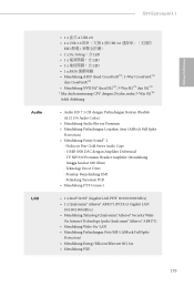
...® Atheros® AR8171) • Mendukung Wake-On-LAN • Mendukung Perlindungan Petir/ESD (ASRock Full Spike Protection) • Mendukung Energy Eicient Ethernet 802.3az • Mendukung PXE 179 X99 Extreme6/3.1 Bahasa Indonesia Audio LAN • 1 x 直式 A USB 2.0 • 2 x... USB 3.0 4 個 USB 3.0 ESD 1 x Dr. Debug,含 LED • 1 x LED • 1 x LED • 1 x BIOS Mendukung AMD Quad CrossFireXTM, 3-...
...® Atheros® AR8171) • Mendukung Wake-On-LAN • Mendukung Perlindungan Petir/ESD (ASRock Full Spike Protection) • Mendukung Energy Eicient Ethernet 802.3az • Mendukung PXE 179 X99 Extreme6/3.1 Bahasa Indonesia Audio LAN • 1 x 直式 A USB 2.0 • 2 x... USB 3.0 4 個 USB 3.0 ESD 1 x Dr. Debug,含 LED • 1 x LED • 1 x LED • 1 x BIOS Mendukung AMD Quad CrossFireXTM, 3-...

RAID Installation Guide
Page 1
...; 8.1 / 8.1 64-bit / 8 / 8 64-bit / 7 / 7 64-bit With RAID Functions 7 2.4 Coniguring a RAID array 8 2.4.1 Coniguring a RAID array Using UEFI Setup Utility ...... 9 2.4.2 Coniguring a RAID array Using Intel RAID BIOS ...... 13 3. Installing Windows® on a HDD larger than 2TB in RAID mode 17 4.
...; 8.1 / 8.1 64-bit / 8 / 8 64-bit / 7 / 7 64-bit With RAID Functions 7 2.4 Coniguring a RAID array 8 2.4.1 Coniguring a RAID array Using UEFI Setup Utility ...... 9 2.4.2 Coniguring a RAID array Using Intel RAID BIOS ...... 13 3. Installing Windows® on a HDD larger than 2TB in RAID mode 17 4.


