

User Manual
Page 4
...Package Contents 1 1.2 Speciications 2 1.3 Motherboard Layout 7 1.4 I/O Panel 10 Chapter 2 Installation 12 2.1 Installing the CPU 13 2.2 Installing the CPU Fan and Heatsink 16 2.3 Installation of Memory Modules (DIMM) 17 2.4 Expansion Slots (PCI Express Slots) 19 2.5 Jumpers Setup 21 2.6 Onboard Headers and Connectors 22 2.7 Smart Switches 27 2.8 Dr. Debug 28 2.9 SLITM , 3-Way SLITMand Quad SLITM Operation Guide 30 2.9.1 Installing Two SLITM-Ready Graphics Cards 30 2.9.2 Installing Three SLITM-Ready Graphics Cards 32 2.9.3 Driver Installation and Setup 34 2.10...
...Package Contents 1 1.2 Speciications 2 1.3 Motherboard Layout 7 1.4 I/O Panel 10 Chapter 2 Installation 12 2.1 Installing the CPU 13 2.2 Installing the CPU Fan and Heatsink 16 2.3 Installation of Memory Modules (DIMM) 17 2.4 Expansion Slots (PCI Express Slots) 19 2.5 Jumpers Setup 21 2.6 Onboard Headers and Connectors 22 2.7 Smart Switches 27 2.8 Dr. Debug 28 2.9 SLITM , 3-Way SLITMand Quad SLITM Operation Guide 30 2.9.1 Installing Two SLITM-Ready Graphics Cards 30 2.9.2 Installing Three SLITM-Ready Graphics Cards 32 2.9.3 Driver Installation and Setup 34 2.10...
User Manual
Page 7
... ind the latest VGA cards and CPU support list on ASRock's website without notice. ASRock website http://www.asrock.com. 1.1 Package Contents • ASRock X99 Extreme6/3.1 Motherboard (ATX Form Factor) • ASRock X99 Extreme6/3.1 Quick Installation Guide • ASRock X99 Extreme6/3.1 Support CD • 1 x I/O Panel Shield • 1 x ASRock USB 3.1 Card/A+A • 1 x ASRock SLI_Bridge_2S Card • 1 x ASRock 3-Way SLI-2S1S Bridge Card • 4 x Serial ATA (SATA) Data Cables (Optional) • 1 x HDD Saver Cable • 1 x Screw for Ultra M.2 Socket • 1 x Screw for...
... ind the latest VGA cards and CPU support list on ASRock's website without notice. ASRock website http://www.asrock.com. 1.1 Package Contents • ASRock X99 Extreme6/3.1 Motherboard (ATX Form Factor) • ASRock X99 Extreme6/3.1 Quick Installation Guide • ASRock X99 Extreme6/3.1 Support CD • 1 x I/O Panel Shield • 1 x ASRock USB 3.1 Card/A+A • 1 x ASRock SLI_Bridge_2S Card • 1 x ASRock 3-Way SLI-2S1S Bridge Card • 4 x Serial ATA (SATA) Data Cables (Optional) • 1 x HDD Saver Cable • 1 x Screw for Ultra M.2 Socket • 1 x Screw for...

User Manual
Page 8
..., un-bufered memory/RDIMM with 28 lanes, PCIE1/PCIE3/PCIE5 will run at x16/x8/x4. * If M.2 PCI Express module is installed, PCIE5 will be disabled. • 2 x PCI Express 2.0 x1 Slots • 1 x mini-PCI Express Slot • Supports AMD Quad CrossFireXTM, 3-Way CrossFireXTM and CrossFireXTM English 2 PCIE5 @ x8 mode) * If you install CPU with Intel® Xeon® processors E5 series in the LGA 2011-3 Socket • Max. PCIE3 @ x16...
..., un-bufered memory/RDIMM with 28 lanes, PCIE1/PCIE3/PCIE5 will run at x16/x8/x4. * If M.2 PCI Express module is installed, PCIE5 will be disabled. • 2 x PCI Express 2.0 x1 Slots • 1 x mini-PCI Express Slot • Supports AMD Quad CrossFireXTM, 3-Way CrossFireXTM and CrossFireXTM English 2 PCIE5 @ x8 mode) * If you install CPU with Intel® Xeon® processors E5 series in the LGA 2011-3 Socket • Max. PCIE3 @ x16...

User Manual
Page 10
...x Clear CMOS Switch • HD Audio Jacks: Rear Speaker / Central / Bass / Line in / Front Speaker / Microphone ASRock USB 3.1 Card/A+A • 2 x USB 3.1 Type-A Ports (10 Gb/s) (Supports ESD Protection (ASRock Full Spike Protection)) Storage • 10 x SATA3 6.0 Gb/s Connectors, support RAID (RAID 0, RAID 1, RAID 5, RAID 10 and Intel Rapid Storage 13), NCQ, AHCI, Hot Plug and ASRock HDD Saver Technology (SSATA3_3 connector is shared with the eSATA port) (SSATA3_2 connector is shared with Ultra M.2 Socket) * RAID is supported on SATA3_0 ~ SATA3_5 ports only. • 1 x SATA Express 10...
...x Clear CMOS Switch • HD Audio Jacks: Rear Speaker / Central / Bass / Line in / Front Speaker / Microphone ASRock USB 3.1 Card/A+A • 2 x USB 3.1 Type-A Ports (10 Gb/s) (Supports ESD Protection (ASRock Full Spike Protection)) Storage • 10 x SATA3 6.0 Gb/s Connectors, support RAID (RAID 0, RAID 1, RAID 5, RAID 10 and Intel Rapid Storage 13), NCQ, AHCI, Hot Plug and ASRock HDD Saver Technology (SSATA3_3 connector is shared with the eSATA port) (SSATA3_2 connector is shared with Ultra M.2 Socket) * RAID is supported on SATA3_0 ~ SATA3_5 ports only. • 1 x SATA Express 10...

User Manual
Page 14
... 288-pin DDR4 DIMM Slots (DDR4_D1, DDR4_C1) 8 Vertical Type A USB 2.0 (USB7) 9 ATX Power Connector (ATXPWR1) 10 USB 3.0 Header (USB3_7_8) 11 USB 3.0 Header (USB3_5_6) 12 Chassis Fan Connector (CHA_FAN3) 13 SATA3 Connectors (SSATA3_0_1) 14 SATA3 Connectors (SSATA3_2_3) 15 SATA3 Connectors (SATA3_0_3) 16 SATA3 Connectors (SATA3_1_4) 17 SATA3 Connectors (SATA3_2_5) 18 SATA Express Connector (SATAE_1) 19 Power LED Header (PLED1) 20 Chassis Speaker Header (SPEAKER1) 21 System Panel Header (PANEL1) 22 Power Switch (PWRBTN1) 23 HDD Saver Connector (SATA_PWR_1) 24 Reset Switch (RSTBTN1) 25 Chassis Fan...
... 288-pin DDR4 DIMM Slots (DDR4_D1, DDR4_C1) 8 Vertical Type A USB 2.0 (USB7) 9 ATX Power Connector (ATXPWR1) 10 USB 3.0 Header (USB3_7_8) 11 USB 3.0 Header (USB3_5_6) 12 Chassis Fan Connector (CHA_FAN3) 13 SATA3 Connectors (SSATA3_0_1) 14 SATA3 Connectors (SSATA3_2_3) 15 SATA3 Connectors (SATA3_0_3) 16 SATA3 Connectors (SATA3_1_4) 17 SATA3 Connectors (SATA3_2_5) 18 SATA Express Connector (SATAE_1) 19 Power LED Header (PLED1) 20 Chassis Speaker Header (SPEAKER1) 21 System Panel Header (PANEL1) 22 Power Switch (PWRBTN1) 23 HDD Saver Connector (SATA_PWR_1) 24 Reset Switch (RSTBTN1) 25 Chassis Fan...

User Manual
Page 32
... GPIO cable. Please connect a hunderbolt™ add-in card (AIC) to manage the power state of HDD. A TPM system also helps enhance network security, protects digital identities, and ensures platform integrity. RRXD1 DDTR#1 DDSR#1 CCTS#1 1 RRI#1 RRTS#1 GND TTXD1 DDCD#1 his connector supports Trusted Platform Module (TPM) system, which can securely store keys, digital certiicates, passwords, and data. HDD Saver Connector (4-pin SATA_PWR_1...
... GPIO cable. Please connect a hunderbolt™ add-in card (AIC) to manage the power state of HDD. A TPM system also helps enhance network security, protects digital identities, and ensures platform integrity. RRXD1 DDTR#1 DDSR#1 CCTS#1 1 RRI#1 RRTS#1 GND TTXD1 DDCD#1 his connector supports Trusted Platform Module (TPM) system, which can securely store keys, digital certiicates, passwords, and data. HDD Saver Connector (4-pin SATA_PWR_1...

User Manual
Page 34
... CPU and memory. A0 - If the problem still exists, please install only one memory module or try installing them in other USB, PCI devices. 01 - 54 (except 0d), 5A- 60 Problem related to memory. If the problem still exists, please clear CMOS and try removing all PCI-E devices or try using another VGA card. If the problem still exists, please remove all SATA devices. A7 Problem related to IDE or SATA devices. Please clear CMOS, re-install the memory and VGA card, and remove other slots...
... CPU and memory. A0 - If the problem still exists, please install only one memory module or try installing them in other USB, PCI devices. 01 - 54 (except 0d), 5A- 60 Problem related to memory. If the problem still exists, please clear CMOS and try removing all PCI-E devices or try using another VGA card. If the problem still exists, please remove all SATA devices. A7 Problem related to IDE or SATA devices. Please clear CMOS, re-install the memory and VGA card, and remove other slots...

User Manual
Page 41
... card, both cards will operate as 12-pipe cards while in CrossFireXTM mode. 5. It is provided with the graphics card you to install up to your system requires. CrossFire Bridge Step 2 Connect two graphics cards by installing a CrossFire Bridge on the CrossFire Bridge Interconnects on the slots. Please refer to three identical PCI Express x16 graphics cards. X99 Extreme6/3.1 2.10 CrossFireXTM, 3-Way CrossFireXTM and Quad CrossFireXTM Operation Guide his motherboard supports...
... card, both cards will operate as 12-pipe cards while in CrossFireXTM mode. 5. It is provided with the graphics card you to install up to your system requires. CrossFire Bridge Step 2 Connect two graphics cards by installing a CrossFire Bridge on the CrossFire Bridge Interconnects on the slots. Please refer to three identical PCI Express x16 graphics cards. X99 Extreme6/3.1 2.10 CrossFireXTM, 3-Way CrossFireXTM and Quad CrossFireXTM Operation Guide his motherboard supports...
User Manual
Page 44
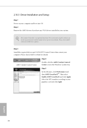
... the AMD Catalyst Control Center icon in your graphics card and click Apply. Step 3 Install the required drivers and CATALYST Control Center then restart your computer and boot into OS. Step 5 In the let pane, click Performance and then AMD CrossFireXTM. Select the GPU number according to installation. 2.10.3 Driver Installation and Setup Step 1 Power on your computer. We recommend using this utility to uninstall any VGA drivers installed...
... the AMD Catalyst Control Center icon in your graphics card and click Apply. Step 3 Install the required drivers and CATALYST Control Center then restart your computer and boot into OS. Step 5 In the let pane, click Performance and then AMD CrossFireXTM. Select the GPU number according to installation. 2.10.3 Driver Installation and Setup Step 1 Power on your computer. We recommend using this utility to uninstall any VGA drivers installed...
User Manual
Page 51
... will be auto-detected and listed on a speciic item then follow the order from top to bottom to display the menu. herefore, the drivers you install can work properly. To improve Windows 7 compatibility, please download and install the following hot ix provided by Microsot. If the Main Menu does not appear automatically, locate and double click on the ile "ASRSETUP.EXE" in your CD-ROM drive.
... will be auto-detected and listed on a speciic item then follow the order from top to bottom to display the menu. herefore, the drivers you install can work properly. To improve Windows 7 compatibility, please download and install the following hot ix provided by Microsot. If the Main Menu does not appear automatically, locate and double click on the ile "ASRSETUP.EXE" in your CD-ROM drive.

User Manual
Page 86
PS2 Y-Cable Enable the PS2 Y-Cable or set this option to Auto. 80 English Serial Port Address Select the address of the Serial port. 4.4.4 Super IO Coniguration Serial Port Enable or disable the Serial port.
PS2 Y-Cable Enable the PS2 Y-Cable or set this option to Auto. 80 English Serial Port Address Select the address of the Serial port. 4.4.4 Super IO Coniguration Serial Port Enable or disable the Serial port.

User Manual
Page 88
... it is recommended to keep the USB 3.0 driver enabled (Must install driver to support USB devices under Windows® 7). Set [Smart Auto] to disable legacy USB support. 4.4.6 USB Coniguration USB Controller Enable or disable all the USB ports. If you encounter USB compatibility issues it is recommended to automatically enable the USB 3.0 driver ater entering the OS (USB 3.0 is enabled in BIOS). Legacy USB Support Enable or disable Legacy OS Support for USB 3 devices. Set [Auto] to disable legacy USB support. Intel USB 3.0 Mode Select Intel® USB 3.0 controller mode.
... it is recommended to keep the USB 3.0 driver enabled (Must install driver to support USB devices under Windows® 7). Set [Smart Auto] to disable legacy USB support. 4.4.6 USB Coniguration USB Controller Enable or disable all the USB ports. If you encounter USB compatibility issues it is recommended to automatically enable the USB 3.0 driver ater entering the OS (USB 3.0 is enabled in BIOS). Legacy USB Support Enable or disable Legacy OS Support for USB 3 devices. Set [Auto] to disable legacy USB support. Intel USB 3.0 Mode Select Intel® USB 3.0 controller mode.

User Manual
Page 92
... Easy RAID Installer Easy RAID Installer helps you to copy the RAID driver from our support CD, Easy Driver Installer is a handy tool in RAID mode. UEFI Tech Service Contact ASRock Tech Service if you can also proceed the re-detection via an USB storage device, then downloads and installs the other required drivers automatically. Please setup network coniguration before using UEFI Tech Service. Boot Manager Boot Manager is recommended to your USB storage device. Re-detect SATA Power Connection Re-detect your HDD coniguration...
... Easy RAID Installer Easy RAID Installer helps you to copy the RAID driver from our support CD, Easy Driver Installer is a handy tool in RAID mode. UEFI Tech Service Contact ASRock Tech Service if you can also proceed the re-detection via an USB storage device, then downloads and installs the other required drivers automatically. Please setup network coniguration before using UEFI Tech Service. Boot Manager Boot Manager is recommended to your USB storage device. Re-detect SATA Power Connection Re-detect your HDD coniguration...

User Manual
Page 94
Save User Default Type a proile name and press enter to conigure internet connection settings for Internet Flash. Network Coniguration Use this to save your settings as user default. Load User Default Load previously saved user defaults. 88 English UEFI Download Server Select a server to download the UEFI irmware. Internet Setting Enable or disable sound efects in the setup utility.
Save User Default Type a proile name and press enter to conigure internet connection settings for Internet Flash. Network Coniguration Use this to save your settings as user default. Load User Default Load previously saved user defaults. 88 English UEFI Download Server Select a server to download the UEFI irmware. Internet Setting Enable or disable sound efects in the setup utility.

Quick Installation Guide
Page 4
... 288-pin DDR4 DIMM Slots (DDR4_D1, DDR4_C1) 8 Vertical Type A USB 2.0 (USB7) 9 ATX Power Connector (ATXPWR1) 10 USB 3.0 Header (USB3_7_8) 11 USB 3.0 Header (USB3_5_6) 12 Chassis Fan Connector (CHA_FAN3) 13 SATA3 Connectors (SSATA3_0_1) 14 SATA3 Connectors (SSATA3_2_3) 15 SATA3 Connectors (SATA3_0_3) 16 SATA3 Connectors (SATA3_1_4) 17 SATA3 Connectors (SATA3_2_5) 18 SATA Express Connector (SATAE_1) 19 Power LED Header (PLED1) 20 Chassis Speaker Header (SPEAKER1) 21 System Panel Header (PANEL1) 22 Power Switch (PWRBTN1) 23 HDD Saver Connector (SATA_PWR_1) 24 Reset Switch (RSTBTN1) 25 Chassis Fan...
... 288-pin DDR4 DIMM Slots (DDR4_D1, DDR4_C1) 8 Vertical Type A USB 2.0 (USB7) 9 ATX Power Connector (ATXPWR1) 10 USB 3.0 Header (USB3_7_8) 11 USB 3.0 Header (USB3_5_6) 12 Chassis Fan Connector (CHA_FAN3) 13 SATA3 Connectors (SSATA3_0_1) 14 SATA3 Connectors (SSATA3_2_3) 15 SATA3 Connectors (SATA3_0_3) 16 SATA3 Connectors (SATA3_1_4) 17 SATA3 Connectors (SATA3_2_5) 18 SATA Express Connector (SATAE_1) 19 Power LED Header (PLED1) 20 Chassis Speaker Header (SPEAKER1) 21 System Panel Header (PANEL1) 22 Power Switch (PWRBTN1) 23 HDD Saver Connector (SATA_PWR_1) 24 Reset Switch (RSTBTN1) 25 Chassis Fan...

Quick Installation Guide
Page 9
PCIE3 @ x16 mode; PCIE5 @ x8 mode) * If you install CPU with Intel® Xeon® processors E5 series in the LGA 2011-3 Socket • Max. capacity of system memory: 128GB (see CAUTION) • Supports Intel® Extreme Memory Proile (XMP) 2.0 Expansion Slot • 3 x PCI Express 3.0 x16 Slots (PCIE1 @ x16 mode; X99 Extreme6/3.1 1.2 Speciications Platform • ATX Form Factor • 2oz Copper PCB • High Density Glass Fabric PCB • Multiple Filter...
PCIE3 @ x16 mode; PCIE5 @ x8 mode) * If you install CPU with Intel® Xeon® processors E5 series in the LGA 2011-3 Socket • Max. capacity of system memory: 128GB (see CAUTION) • Supports Intel® Extreme Memory Proile (XMP) 2.0 Expansion Slot • 3 x PCI Express 3.0 x16 Slots (PCIE1 @ x16 mode; X99 Extreme6/3.1 1.2 Speciications Platform • ATX Form Factor • 2oz Copper PCB • High Density Glass Fabric PCB • Multiple Filter...

Quick Installation Guide
Page 11
...x Clear CMOS Switch • HD Audio Jacks: Rear Speaker / Central / Bass / Line in / Front Speaker / Microphone ASRock USB 3.1 Card/A+A • 2 x USB 3.1 Type-A Ports (10 Gb/s) (Supports ESD Protection (ASRock Full Spike Protection)) Storage • 10 x SATA3 6.0 Gb/s Connectors, support RAID (RAID 0, RAID 1, RAID 5, RAID 10 and Intel Rapid Storage 13), NCQ, AHCI, Hot Plug and ASRock HDD Saver Technology (SSATA3_3 connector is shared with the eSATA port) (SSATA3_2 connector is shared with Ultra M.2 Socket) * RAID is supported on SATA3_0 ~ SATA3_5 ports only. • 1 x SATA Express 10...
...x Clear CMOS Switch • HD Audio Jacks: Rear Speaker / Central / Bass / Line in / Front Speaker / Microphone ASRock USB 3.1 Card/A+A • 2 x USB 3.1 Type-A Ports (10 Gb/s) (Supports ESD Protection (ASRock Full Spike Protection)) Storage • 10 x SATA3 6.0 Gb/s Connectors, support RAID (RAID 0, RAID 1, RAID 5, RAID 10 and Intel Rapid Storage 13), NCQ, AHCI, Hot Plug and ASRock HDD Saver Technology (SSATA3_3 connector is shared with the eSATA port) (SSATA3_2 connector is shared with Ultra M.2 Socket) * RAID is supported on SATA3_0 ~ SATA3_5 ports only. • 1 x SATA Express 10...
Quick Installation Guide
Page 27
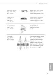
..., which can securely store keys, digital certiicates, passwords, and data. TPM Header (17-pin TPMS1) (see p.1, No. 31) Please connect the HDD Saver 1 Cable to manage the power state of HDD. A TPM system also helps enhance network security, protects digital identities, and ensures platform integrity. X99 Extreme6/3.1 HDD Saver Connector (4-pin SATA_PWR_1) (see p.1, No. 23) hunderbolt AIC Connector (5-pin TBT1) (see p.1, No. 32) Serial Port Header (9-pin COM1) (see p.1, No. 33...
..., which can securely store keys, digital certiicates, passwords, and data. TPM Header (17-pin TPMS1) (see p.1, No. 31) Please connect the HDD Saver 1 Cable to manage the power state of HDD. A TPM system also helps enhance network security, protects digital identities, and ensures platform integrity. X99 Extreme6/3.1 HDD Saver Connector (4-pin SATA_PWR_1) (see p.1, No. 23) hunderbolt AIC Connector (5-pin TBT1) (see p.1, No. 32) Serial Port Header (9-pin COM1) (see p.1, No. 33...
Quick Installation Guide
Page 29
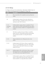
...slots. Please clear CMOS, re-install the memory and VGA card, and remove other memory modules. 61 - 91 Chipset initialization error. Please re-install IDE and SATA devices. Please re-install the CPU and memory then clear CMOS. A0 - Please re-install the CPU and memory. If the problem still exists, please remove all SATA devices. b0 Problem related to IDE or SATA devices. X99 Extreme6/3.1 2.8 Dr. Debug Dr. Debug is installed correctly and then clear CMOS. 0d Problem related to memory, VGA card or other devices. Please re-install PCI-E devices or try using...
...slots. Please clear CMOS, re-install the memory and VGA card, and remove other memory modules. 61 - 91 Chipset initialization error. Please re-install IDE and SATA devices. Please re-install the CPU and memory then clear CMOS. A0 - Please re-install the CPU and memory. If the problem still exists, please remove all SATA devices. b0 Problem related to IDE or SATA devices. X99 Extreme6/3.1 2.8 Dr. Debug Dr. Debug is installed correctly and then clear CMOS. 0d Problem related to memory, VGA card or other devices. Please re-install PCI-E devices or try using...

RAID Installation Guide
Page 7
... instructions on your USB lash drive into a USB port. STEP 1: Setting the BIOS RAID Items After installing the hard disk drives, please set the option SATA Mode Selection to [RAID]. Boot your SATA / SATA2 / SATA3 HDDs with just one simple click in the BIOS before you want to install Windows® 8.1 / 8.1 64-bit /8 / 8 64-bit / 7 / 7 64-bit OS on your system, and press key to complete the process. B. A. 2.3 Installing Windows® 8.1 / 8.1 64-bit / 8 / 8 64-bit / 7 / 7 64-bit With RAID Functions If you exit BIOS setup...
... instructions on your USB lash drive into a USB port. STEP 1: Setting the BIOS RAID Items After installing the hard disk drives, please set the option SATA Mode Selection to [RAID]. Boot your SATA / SATA2 / SATA3 HDDs with just one simple click in the BIOS before you want to install Windows® 8.1 / 8.1 64-bit /8 / 8 64-bit / 7 / 7 64-bit OS on your system, and press key to complete the process. B. A. 2.3 Installing Windows® 8.1 / 8.1 64-bit / 8 / 8 64-bit / 7 / 7 64-bit With RAID Functions If you exit BIOS setup...


