
User Manual
Page 5
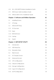
2.10 M.2_SSD (NGFF) Module Installation Guide 36 2.11 HDD Saver Cable Installation Guide 39 2.12 ASRock USB 3.1/A+C Installation Guide 40 Chapter 3 Software and Utilities Operation 42 3.1 Installing Drivers 42 3.2 A-Tuning 43 3.3 ASRock APP Shop 49 3.3.1 UI Overview 49 3.3.2 Apps 50 3.3.3 BIOS & Drivers 53 3.3.4 Setting 54 3.4 Start8 55 Chapter 4 UEFI SETUP UTILITY 58 4.1 Introduction 58...
2.10 M.2_SSD (NGFF) Module Installation Guide 36 2.11 HDD Saver Cable Installation Guide 39 2.12 ASRock USB 3.1/A+C Installation Guide 40 Chapter 3 Software and Utilities Operation 42 3.1 Installing Drivers 42 3.2 A-Tuning 43 3.3 ASRock APP Shop 49 3.3.1 UI Overview 49 3.3.2 Apps 50 3.3.3 BIOS & Drivers 53 3.3.4 Setting 54 3.4 Start8 55 Chapter 4 UEFI SETUP UTILITY 58 4.1 Introduction 58...
User Manual
Page 7
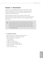
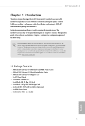
... Guide • ASRock X99 Extreme4/3.1 Support CD • 1 x I/O Panel Shield • 1 x ASRock USB 3.1/A+C • 1 x ASRock SLI_Bridge_2S Card • 1 x ASRock 3-Way SLI-2S1S Bridge Card • 4 x Serial ATA (SATA) Data Cables (Optional) • 1 x HDD Saver Cable • 1 x Screw for purchasing ASRock X99 Extreme4/3.1 motherboard, a reliable motherboard produced under ASRock's consistently stringent quality control. Chapter 3 contains the operation guide of the BIOS setup.
... Guide • ASRock X99 Extreme4/3.1 Support CD • 1 x I/O Panel Shield • 1 x ASRock USB 3.1/A+C • 1 x ASRock SLI_Bridge_2S Card • 1 x ASRock 3-Way SLI-2S1S Bridge Card • 4 x Serial ATA (SATA) Data Cables (Optional) • 1 x HDD Saver Cable • 1 x Screw for purchasing ASRock X99 Extreme4/3.1 motherboard, a reliable motherboard produced under ASRock's consistently stringent quality control. Chapter 3 contains the operation guide of the BIOS setup.
User Manual
Page 10
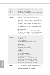
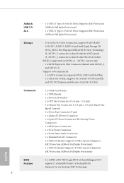
... support RAID (RAID 0, RAID 1, RAID 5, RAID 10 and Intel Rapid Storage 13), NCQ, AHCI, Hot Plug and ASRock HDD Saver Technology (S_SATA3_3 connector is shared with the eSATA port) (S_SATA3_2 connector is shared with Ultra M.2 Socket) * RAID... USB 2.0 ports) (Supports ESD Protection (ASRock Full Spike Protection)) • 1 x USB 3.0 Header (Supports 2 USB 3.0 ports) (Supports ESD Protection (ASRock Full Spike Protection)) English BIOS Feature • 2 x 128Mb AMI UEFI Legal BIOS with multilingual GUI support (1 x Main BIOS and 1 x Backup BIOS) • Supports Secure Backup UEFI Technology ...
... support RAID (RAID 0, RAID 1, RAID 5, RAID 10 and Intel Rapid Storage 13), NCQ, AHCI, Hot Plug and ASRock HDD Saver Technology (S_SATA3_3 connector is shared with the eSATA port) (S_SATA3_2 connector is shared with Ultra M.2 Socket) * RAID... USB 2.0 ports) (Supports ESD Protection (ASRock Full Spike Protection)) • 1 x USB 3.0 Header (Supports 2 USB 3.0 ports) (Supports ESD Protection (ASRock Full Spike Protection)) English BIOS Feature • 2 x 128Mb AMI UEFI Legal BIOS with multilingual GUI support (1 x Main BIOS and 1 x Backup BIOS) • Supports Secure Backup UEFI Technology ...
User Manual
Page 11
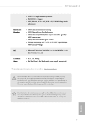
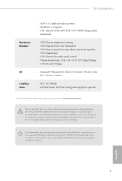
... the memory that there is required) * For detailed product information, please visit our website: http://www.asrock.com Please realize that Windows® cannot use. X99 Extreme4/3.1 Hardware Monitor OS Certiications • ACPI 1.1 Compliant wake up events • SMBIOS 2.3.1 Support •...ErP/EuP Ready (ErP/EuP ready power supply is a certain risk involved with overclocking, including adjusting the setting in the BIOS, applying Untied Overclocking Technology, or using third-party overclocking tools. English 5 adjustment • CPU/Chassis temperature sensing •...
... the memory that there is required) * For detailed product information, please visit our website: http://www.asrock.com Please realize that Windows® cannot use. X99 Extreme4/3.1 Hardware Monitor OS Certiications • ACPI 1.1 Compliant wake up events • SMBIOS 2.3.1 Support •...ErP/EuP Ready (ErP/EuP ready power supply is a certain risk involved with overclocking, including adjusting the setting in the BIOS, applying Untied Overclocking Technology, or using third-party overclocking tools. English 5 adjustment • CPU/Chassis temperature sensing •...
User Manual
Page 12
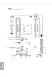
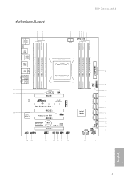
...: Center: FRONT Bottom: MIC IN USB3_4_5 1 32 PCIE_PWR1 31 PWR_FAN1 PCIE1 M2_1 LAN Ultra M.2 PCIe Gen3 x4 CT5 CT4 CT3 CT2 CT1 X99 Extreme4/3.1 PCIE2 30 Purity SoundTM 2 PCI Express 3.0 RoHS PCIE3 1 T BT1 PCIE4 CMOS Battery Super USB 3.1 I/O PCIE5 HD_AUDIO1 1 1 TPMS1 COM1... 1 29 28 27 26 25 24 23 CHA_FAN3 S_SATA3_0_1 S_SATA3_2_3 SATA3_0_3 SATA3_1_4 Intel X99 SATA3_2_5 SATAE_1 BIOS_A_LED CHA_FAN2 SATA_PWR_1 1 PLED1 CHA_FAN1 1 1 SPEAKER1 BIOS_B_LED PLED PWRBTN 128Mb BIOS BIOS_A 128Mb BIOS BIOS_B 1 HDLED RESET PANEL1 22 21 9 10 11 12 13 14 15...
...: Center: FRONT Bottom: MIC IN USB3_4_5 1 32 PCIE_PWR1 31 PWR_FAN1 PCIE1 M2_1 LAN Ultra M.2 PCIe Gen3 x4 CT5 CT4 CT3 CT2 CT1 X99 Extreme4/3.1 PCIE2 30 Purity SoundTM 2 PCI Express 3.0 RoHS PCIE3 1 T BT1 PCIE4 CMOS Battery Super USB 3.1 I/O PCIE5 HD_AUDIO1 1 1 TPMS1 COM1... 1 29 28 27 26 25 24 23 CHA_FAN3 S_SATA3_0_1 S_SATA3_2_3 SATA3_0_3 SATA3_1_4 Intel X99 SATA3_2_5 SATAE_1 BIOS_A_LED CHA_FAN2 SATA_PWR_1 1 PLED1 CHA_FAN1 1 1 SPEAKER1 BIOS_B_LED PLED PWRBTN 128Mb BIOS BIOS_A 128Mb BIOS BIOS_B 1 HDLED RESET PANEL1 22 21 9 10 11 12 13 14 15...
User Manual
Page 13
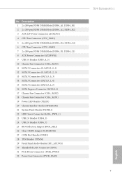
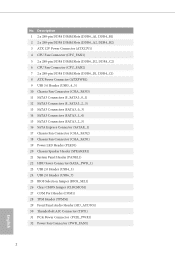
... (SATA_PWR_1) 23 USB 2.0 Header (USB4_5) 24 USB 2.0 Header (USB6_7) 25 BIOS Selection Jumper (BIOS_SEL1) 26 Clear CMOS Jumper (CLRCMOS1) 27 COM Port Header (COM1) 28 TPM Header (TPMS1) 29 Front Panel Audio Header (HD_AUDIO1) 30 hunderbolt AIC Connector (TBT1) 31 PCIe Power Connector (PCIE_PWR1) 32 Power Fan Connector (PWR_FAN1) X99 Extreme4/3.1 7 English No.
... (SATA_PWR_1) 23 USB 2.0 Header (USB4_5) 24 USB 2.0 Header (USB6_7) 25 BIOS Selection Jumper (BIOS_SEL1) 26 Clear CMOS Jumper (CLRCMOS1) 27 COM Port Header (COM1) 28 TPM Header (TPMS1) 29 Front Panel Audio Header (HD_AUDIO1) 30 hunderbolt AIC Connector (TBT1) 31 PCIe Power Connector (PCIE_PWR1) 32 Power Fan Connector (PWR_FAN1) X99 Extreme4/3.1 7 English No.
User Manual
Page 25
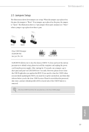
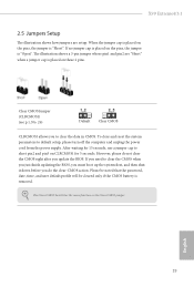
... must boot up the system irst, and then shut it down before you update the BIOS. To clear and reset the system parameters to clear the data in CMOS. X99 Extreme4/3.1 2.5 Jumpers Setup he illustration shows how jumpers are "Short" when a jumper cap is placed on the pins, the jumper is "Open". he...
... must boot up the system irst, and then shut it down before you update the BIOS. To clear and reset the system parameters to clear the data in CMOS. X99 Extreme4/3.1 2.5 Jumpers Setup he illustration shows how jumpers are "Short" when a jumper cap is placed on the pins, the jumper is "Open". he...

User Manual
Page 26
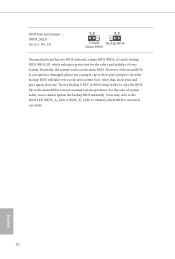
... Backup BIOS (Main BIOS) his motherboard has two BIOS onboard, a main BIOS (BIOS_A) and a backup BIOS (BIOS_B), which BIOS is corrupted or damaged, please use "Secure Backup UEFI" in BIOS setup utility to copy the BIOS ile to the main BIOS to ensure normal system operation. Users may refer to the BIOS LED ... cap to identify which enhances protection for the safety and stability of system safety, users cannot update the backup BIOS manually. However, if the main BIOS is activated currently. English 20 For the sake of your system. Normally, the system works on the next system...
... Backup BIOS (Main BIOS) his motherboard has two BIOS onboard, a main BIOS (BIOS_A) and a backup BIOS (BIOS_B), which BIOS is corrupted or damaged, please use "Secure Backup UEFI" in BIOS setup utility to copy the BIOS ile to the main BIOS to ensure normal system operation. Users may refer to the BIOS LED ... cap to identify which enhances protection for the safety and stability of system safety, users cannot update the backup BIOS manually. However, if the main BIOS is activated currently. English 20 For the sake of your system. Normally, the system works on the next system...
User Manual
Page 53
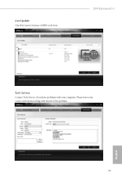
Please leave your computer. Live Update Check for newer versions of the problem. X99 Extreme4/3.1 Tech Service Contact Tech Service if you have problems with your contact information along with details of BIOS or drivers. English 47
Please leave your computer. Live Update Check for newer versions of the problem. X99 Extreme4/3.1 Tech Service Contact Tech Service if you have problems with your contact information along with details of BIOS or drivers. English 47
User Manual
Page 59
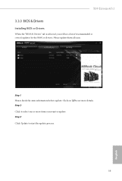
Step 1 Please check the item information before update. Step 3 Click Update to update. Please update them all soon. Click to select one or more items you will see more details. Click on Step 2 to see a list of recommended or critical updates for the BIOS or drivers. X99 Extreme4/3.1 3.3.3 BIOS & Drivers Installing BIOS or Drivers When the "BIOS & Drivers" tab is selected, you want to start the update process. 53 English
Step 1 Please check the item information before update. Step 3 Click Update to update. Please update them all soon. Click to select one or more items you will see more details. Click on Step 2 to see a list of recommended or critical updates for the BIOS or drivers. X99 Extreme4/3.1 3.3.3 BIOS & Drivers Installing BIOS or Drivers When the "BIOS & Drivers" tab is selected, you want to start the update process. 53 English
User Manual
Page 66
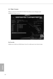
4.2 Main Screen When you enter the UEFI SETUP UTILITY, the Main screen will appear and display the system overview. My Favorite Display your collection of BIOS items. Press F5 to add/remove your favorite items. 60 English
4.2 Main Screen When you enter the UEFI SETUP UTILITY, the Main screen will appear and display the system overview. My Favorite Display your collection of BIOS items. Press F5 to add/remove your favorite items. 60 English
User Manual
Page 85
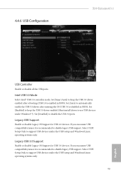
...to automatically enable the USB 3.0 driver ater entering the OS (USB 3.0 is enabled in BIOS). Legacy USB Support Enable or disable Legacy OS Support for USB 3.0 devices. 4.4.6 USB Coniguration X99 Extreme4/3.1 USB Controller Enable or disable all the USB ports. Intel USB 3.0 Mode Select Intel&#...174; USB 3.0 controller mode. Set [Enabled] to keep the USB 3.0 driver enabled ater rebooting (USB 3.0 is disabled in BIOS). Legacy USB 3.0 Support ...
...to automatically enable the USB 3.0 driver ater entering the OS (USB 3.0 is enabled in BIOS). Legacy USB Support Enable or disable Legacy OS Support for USB 3.0 devices. 4.4.6 USB Coniguration X99 Extreme4/3.1 USB Controller Enable or disable all the USB ports. Intel USB 3.0 Mode Select Intel&#...174; USB 3.0 controller mode. Set [Enabled] to keep the USB 3.0 driver enabled ater rebooting (USB 3.0 is disabled in BIOS). Legacy USB 3.0 Support ...
User Manual
Page 91
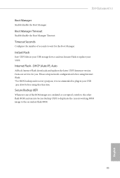
...update your USB pen drive before using Internet Flash. *For BIOS backup and recovery purpose, it is recommended to wait for you. Secure Backup UEFI Whenever one of seconds to plug in your UEFI. X99 Extreme4/3.1 Boot Manager Enable/disable the Boot Manager. Please setup ...network coniguration before using this function. Internet Flash - Boot Manager Timeout Enable/disable the Boot Manager Timeout. DHCP (Auto IP), Auto ASRock Internet Flash downloads and updates the ...
...update your USB pen drive before using Internet Flash. *For BIOS backup and recovery purpose, it is recommended to wait for you. Secure Backup UEFI Whenever one of seconds to plug in your UEFI. X99 Extreme4/3.1 Boot Manager Enable/disable the Boot Manager. Please setup ...network coniguration before using this function. Internet Flash - Boot Manager Timeout Enable/disable the Boot Manager Timeout. DHCP (Auto IP), Auto ASRock Internet Flash downloads and updates the ...
Quick Installation Guide
Page 3
...: Center: FRONT Bottom: MIC IN USB3_4_5 1 32 PCIE_PWR1 31 PWR_FAN1 PCIE1 M2_1 LAN Ultra M.2 PCIe Gen3 x4 CT5 CT4 CT3 CT2 CT1 X99 Extreme4/3.1 PCIE2 30 Purity SoundTM 2 PCI Express 3.0 RoHS PCIE3 1 T BT1 PCIE4 CMOS Battery Super USB 3.1 I/O PCIE5 HD_AUDIO1 1 1 TPMS1 COM1... 1 29 28 27 26 25 24 23 CHA_FAN3 S_SATA3_0_1 S_SATA3_2_3 SATA3_0_3 SATA3_1_4 Intel X99 SATA3_2_5 SATAE_1 BIOS_A_LED CHA_FAN2 SATA_PWR_1 1 PLED1 CHA_FAN1 1 1 SPEAKER1 BIOS_B_LED PLED PWRBTN 128Mb BIOS BIOS_A 128Mb BIOS BIOS_B 1 HDLED RESET PANEL1 22 21 9 10 11 12 13 14 15...
...: Center: FRONT Bottom: MIC IN USB3_4_5 1 32 PCIE_PWR1 31 PWR_FAN1 PCIE1 M2_1 LAN Ultra M.2 PCIe Gen3 x4 CT5 CT4 CT3 CT2 CT1 X99 Extreme4/3.1 PCIE2 30 Purity SoundTM 2 PCI Express 3.0 RoHS PCIE3 1 T BT1 PCIE4 CMOS Battery Super USB 3.1 I/O PCIE5 HD_AUDIO1 1 1 TPMS1 COM1... 1 29 28 27 26 25 24 23 CHA_FAN3 S_SATA3_0_1 S_SATA3_2_3 SATA3_0_3 SATA3_1_4 Intel X99 SATA3_2_5 SATAE_1 BIOS_A_LED CHA_FAN2 SATA_PWR_1 1 PLED1 CHA_FAN1 1 1 SPEAKER1 BIOS_B_LED PLED PWRBTN 128Mb BIOS BIOS_A 128Mb BIOS BIOS_B 1 HDLED RESET PANEL1 22 21 9 10 11 12 13 14 15...
Quick Installation Guide
Page 4
... (PLED1) 20 Chassis Speaker Header (SPEAKER1) 21 System Panel Header (PANEL1) 22 HDD Saver Connector (SATA_PWR_1) 23 USB 2.0 Header (USB4_5) 24 USB 2.0 Header (USB6_7) 25 BIOS Selection Jumper (BIOS_SEL1) 26 Clear CMOS Jumper (CLRCMOS1) 27 COM Port Header (COM1) 28 TPM Header (TPMS1) 29 Front Panel Audio Header (HD_AUDIO1) 30 hunderbolt...
... (PLED1) 20 Chassis Speaker Header (SPEAKER1) 21 System Panel Header (PANEL1) 22 HDD Saver Connector (SATA_PWR_1) 23 USB 2.0 Header (USB4_5) 24 USB 2.0 Header (USB6_7) 25 BIOS Selection Jumper (BIOS_SEL1) 26 Clear CMOS Jumper (CLRCMOS1) 27 COM Port Header (COM1) 28 TPM Header (TPMS1) 29 Front Panel Audio Header (HD_AUDIO1) 30 hunderbolt...
Quick Installation Guide
Page 7
... content of this documentation, Chapter 1 and 2 contains the introduction of the BIOS setup. ASRock website http://www.asrock.com. 1.1 Package Contents • ASRock X99 Extreme4/3.1 Motherboard (ATX Form Factor) • ASRock X99 Extreme4/3.1 Quick Installation Guide • ASRock X99 Extreme4/3.1 Support CD • 1 x I/O Panel Shield • 1 x ASRock USB 3.1/A+C • 1 x ASRock SLI_Bridge_2S Card • 1 x ASRock 3-Way SLI-2S1S Bridge Card • 4 x Serial ATA (SATA) Data Cables...
... content of this documentation, Chapter 1 and 2 contains the introduction of the BIOS setup. ASRock website http://www.asrock.com. 1.1 Package Contents • ASRock X99 Extreme4/3.1 Motherboard (ATX Form Factor) • ASRock X99 Extreme4/3.1 Quick Installation Guide • ASRock X99 Extreme4/3.1 Support CD • 1 x I/O Panel Shield • 1 x ASRock USB 3.1/A+C • 1 x ASRock SLI_Bridge_2S Card • 1 x ASRock 3-Way SLI-2S1S Bridge Card • 4 x Serial ATA (SATA) Data Cables...
Quick Installation Guide
Page 10
... support RAID (RAID 0, RAID 1, RAID 5, RAID 10 and Intel Rapid Storage 13), NCQ, AHCI, Hot Plug and ASRock HDD Saver Technology (S_SATA3_3 connector is shared with the eSATA port) (S_SATA3_2 connector is shared with Ultra M.2 Socket) * RAID... USB 2.0 ports) (Supports ESD Protection (ASRock Full Spike Protection)) • 1 x USB 3.0 Header (Supports 2 USB 3.0 ports) (Supports ESD Protection (ASRock Full Spike Protection)) English BIOS Feature • 2 x 128Mb AMI UEFI Legal BIOS with multilingual GUI support (1 x Main BIOS and 1 x Backup BIOS) • Supports Secure Backup UEFI Technology ...
... support RAID (RAID 0, RAID 1, RAID 5, RAID 10 and Intel Rapid Storage 13), NCQ, AHCI, Hot Plug and ASRock HDD Saver Technology (S_SATA3_3 connector is shared with the eSATA port) (S_SATA3_2 connector is shared with Ultra M.2 Socket) * RAID... USB 2.0 ports) (Supports ESD Protection (ASRock Full Spike Protection)) • 1 x USB 3.0 Header (Supports 2 USB 3.0 ports) (Supports ESD Protection (ASRock Full Spike Protection)) English BIOS Feature • 2 x 128Mb AMI UEFI Legal BIOS with multilingual GUI support (1 x Main BIOS and 1 x Backup BIOS) • Supports Secure Backup UEFI Technology ...
Quick Installation Guide
Page 11
...• ErP/EuP Ready (ErP/EuP ready power supply is a certain risk involved with overclocking, including adjusting the setting in the BIOS, applying Untied Overclocking Technology, or using third-party overclocking tools. Due to limitation, the actual memory size may afect your system's ... operating systems do not have such limitations. X99 Extreme4/3.1 Hardware Monitor OS Certiications • ACPI 1.1 Compliant wake up events • SMBIOS 2.3.1 Support • CPU, DRAM, PCH 1.05V, PCH 1.5V, VPPM Voltage Multi- You can use ASRock XFast RAM to the components and devices of...
...• ErP/EuP Ready (ErP/EuP ready power supply is a certain risk involved with overclocking, including adjusting the setting in the BIOS, applying Untied Overclocking Technology, or using third-party overclocking tools. Due to limitation, the actual memory size may afect your system's ... operating systems do not have such limitations. X99 Extreme4/3.1 Hardware Monitor OS Certiications • ACPI 1.1 Compliant wake up events • SMBIOS 2.3.1 Support • CPU, DRAM, PCH 1.05V, PCH 1.5V, VPPM Voltage Multi- You can use ASRock XFast RAM to the components and devices of...
Quick Installation Guide
Page 21
... pin3 on the pins, the jumper is "Short". To clear and reset the system parameters to clear the CMOS when you just inish updating the BIOS, you must boot up the system irst, and then shut it down before you need to default setup, please turn of the computer and unplug... Clear CMOS CLRCMOS1 allows you update the BIOS. he Clear CMOS Switch has the same function as the Clear CMOS jumper. When the jumper cap is placed on CLRCMOS1 for 5 seconds. If no jumper cap is placed on the pins, the jumper is removed. X99 Extreme4/3.1 2.5 Jumpers Setup he illustration shows how jumpers...
... pin3 on the pins, the jumper is "Short". To clear and reset the system parameters to clear the CMOS when you just inish updating the BIOS, you must boot up the system irst, and then shut it down before you need to default setup, please turn of the computer and unplug... Clear CMOS CLRCMOS1 allows you update the BIOS. he Clear CMOS Switch has the same function as the Clear CMOS jumper. When the jumper cap is placed on CLRCMOS1 for 5 seconds. If no jumper cap is placed on the pins, the jumper is removed. X99 Extreme4/3.1 2.5 Jumpers Setup he illustration shows how jumpers...
Quick Installation Guide
Page 22
... and stability of system safety, users cannot update the backup BIOS manually. Normally, the system works on the next system boot. BIOS Selection Jumper (BIOS_SEL1) (see p.1, No. 25) Default Backup BIOS (Main BIOS) his motherboard has two BIOS onboard, a main BIOS (BIOS_A) and a backup BIOS (BIOS_B), which BIOS is corrupted or damaged, please use "Secure Backup UEFI" in...
... and stability of system safety, users cannot update the backup BIOS manually. Normally, the system works on the next system boot. BIOS Selection Jumper (BIOS_SEL1) (see p.1, No. 25) Default Backup BIOS (Main BIOS) his motherboard has two BIOS onboard, a main BIOS (BIOS_A) and a backup BIOS (BIOS_B), which BIOS is corrupted or damaged, please use "Secure Backup UEFI" in...


