

User Manual
Page 2
... such damages arising from any interference received, including interference that may apply, see www.dtsc.ca.gov/hazardouswaste/ perchlorate" ASRock Website: http://www.asrock.com CALIFORNIA, USA ONLY he Lithium battery adopted on this motherboard contains Perchlorate, a toxic substance controlled in this documentation. Copyright Notice: No part of any kind, either expressed or...
... such damages arising from any interference received, including interference that may apply, see www.dtsc.ca.gov/hazardouswaste/ perchlorate" ASRock Website: http://www.asrock.com CALIFORNIA, USA ONLY he Lithium battery adopted on this motherboard contains Perchlorate, a toxic substance controlled in this documentation. Copyright Notice: No part of any kind, either expressed or...
User Manual
Page 4
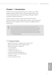
Contents Chapter 1 Introduction 1 1.1 Package Contents 1 1.2 Speciications 2 1.3 Motherboard Layout 6 1.4 I/O Panel 8 Chapter 2 Installation 10 2.1 Installing the CPU 11 2.2 Installing the CPU Fan and Heatsink 14 2.3 Installation of Memory Modules (DIMM) 15 2.4 Expansion Slots (PCI ...
Contents Chapter 1 Introduction 1 1.1 Package Contents 1 1.2 Speciications 2 1.3 Motherboard Layout 6 1.4 I/O Panel 8 Chapter 2 Installation 10 2.1 Installing the CPU 11 2.2 Installing the CPU Fan and Heatsink 14 2.3 Installation of Memory Modules (DIMM) 15 2.4 Expansion Slots (PCI ...
User Manual
Page 7
... http://www.asrock.com. 1.1 Package Contents • ASRock X99 Extreme4/3.1 Motherboard (ATX Form Factor) • ASRock X99 Extreme4/3.1 Quick Installation Guide • ASRock X99 Extreme4/3.1 Support CD • 1 x I/O Panel Shield • 1 x ASRock USB 3.1/A+C • 1 x ASRock SLI_Bridge_2S Card • 1 x ASRock 3-Way SLI-2S1S Bridge Card • 4 x Serial ATA (SATA) Data Cables (Optional) • 1 x HDD Saver Cable • 1 x Screw for purchasing ASRock X99 Extreme4/3.1 motherboard, a reliable motherboard produced under ASRock's consistently stringent...
... http://www.asrock.com. 1.1 Package Contents • ASRock X99 Extreme4/3.1 Motherboard (ATX Form Factor) • ASRock X99 Extreme4/3.1 Quick Installation Guide • ASRock X99 Extreme4/3.1 Support CD • 1 x I/O Panel Shield • 1 x ASRock USB 3.1/A+C • 1 x ASRock SLI_Bridge_2S Card • 1 x ASRock 3-Way SLI-2S1S Bridge Card • 4 x Serial ATA (SATA) Data Cables (Optional) • 1 x HDD Saver Cable • 1 x Screw for purchasing ASRock X99 Extreme4/3.1 motherboard, a reliable motherboard produced under ASRock's consistently stringent...
User Manual
Page 12
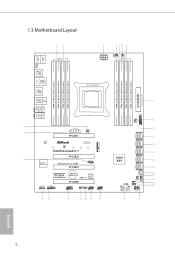
1.3 Motherboard Layout 12 3 4 56 7 PS2 Mouse PS2 Keyboard CLRC BTN1 USB 2.0 T: ... MIC IN USB3_4_5 1 32 PCIE_PWR1 31 PWR_FAN1 PCIE1 M2_1 LAN Ultra M.2 PCIe Gen3 x4 CT5 CT4 CT3 CT2 CT1 X99 Extreme4/3.1 PCIE2 30 Purity SoundTM 2 PCI Express 3.0 RoHS PCIE3 1 T BT1 PCIE4 CMOS Battery Super USB 3.1 I/O PCIE5... 1 1 1 USB6_7 USB4_5 1 29 28 27 26 25 24 23 CHA_FAN3 S_SATA3_0_1 S_SATA3_2_3 SATA3_0_3 SATA3_1_4 Intel X99 SATA3_2_5 SATAE_1 BIOS_A_LED CHA_FAN2 SATA_PWR_1 1 PLED1 CHA_FAN1 1 1 SPEAKER1 BIOS_B_LED PLED PWRBTN 128Mb BIOS BIOS_A 128Mb BIOS ...
1.3 Motherboard Layout 12 3 4 56 7 PS2 Mouse PS2 Keyboard CLRC BTN1 USB 2.0 T: ... MIC IN USB3_4_5 1 32 PCIE_PWR1 31 PWR_FAN1 PCIE1 M2_1 LAN Ultra M.2 PCIe Gen3 x4 CT5 CT4 CT3 CT2 CT1 X99 Extreme4/3.1 PCIE2 30 Purity SoundTM 2 PCI Express 3.0 RoHS PCIE3 1 T BT1 PCIE4 CMOS Battery Super USB 3.1 I/O PCIE5... 1 1 1 USB6_7 USB4_5 1 29 28 27 26 25 24 23 CHA_FAN3 S_SATA3_0_1 S_SATA3_2_3 SATA3_0_3 SATA3_1_4 Intel X99 SATA3_2_5 SATAE_1 BIOS_A_LED CHA_FAN2 SATA_PWR_1 1 PLED1 CHA_FAN1 1 1 SPEAKER1 BIOS_B_LED PLED PWRBTN 128Mb BIOS BIOS_A 128Mb BIOS ...
User Manual
Page 16
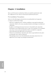
...handle the components. • Hold components by the edges and do so may damage the motherboard. 10 English Failure to do not touch the ICs. • Whenever you install motherboard components or change any components, place them on a carpet. Doing so may cause physical ...injuries and damages to motherboard components. • In order to avoid damage from static electricity to unplug the power cord before you uninstall any motherboard settings. • Make sure to the motherboard's components, NEVER place your chassis to the chassis, ...
...handle the components. • Hold components by the edges and do so may damage the motherboard. 10 English Failure to do not touch the ICs. • Whenever you install motherboard components or change any components, place them on a carpet. Doing so may cause physical ...injuries and damages to motherboard components. • In order to avoid damage from static electricity to unplug the power cord before you uninstall any motherboard settings. • Make sure to the motherboard's components, NEVER place your chassis to the chassis, ...

User Manual
Page 19
X99 Extreme4/3.1 6 A B 7 A B 8 Please save and replace the cover if the processor is removed. he cover must be placed if you wish to return the motherboard for ater service. 13 English
X99 Extreme4/3.1 6 A B 7 A B 8 Please save and replace the cover if the processor is removed. he cover must be placed if you wish to return the motherboard for ater service. 13 English

User Manual
Page 21
...same brand, speed, size and chip-type) DDR4 DIMM pairs. 2. otherwise, this motherboard and DIMM may be damaged. 3. It is activated. It will cause permanent damage to the motherboard and the DIMM if you always need to use more than four memory modules, please ...to DDR4_C2.) • If only two memory modules are installed, then Triple Channel Memory Technology is activated. English 15 X99 Extreme4/3.1 2.3 Installation of Memory Modules (DIMM) his motherboard provides eight 288-pin DDR4 (Double Data Rate 4) DIMM slots, and supports Quad Channel Memory Technology. 1. If three...
...same brand, speed, size and chip-type) DDR4 DIMM pairs. 2. otherwise, this motherboard and DIMM may be damaged. 3. It is activated. It will cause permanent damage to the motherboard and the DIMM if you always need to use more than four memory modules, please ...to DDR4_C2.) • If only two memory modules are installed, then Triple Channel Memory Technology is activated. English 15 X99 Extreme4/3.1 2.3 Installation of Memory Modules (DIMM) his motherboard provides eight 288-pin DDR4 (Double Data Rate 4) DIMM slots, and supports Quad Channel Memory Technology. 1. If three...

User Manual
Page 23
.... PCIE4 (PCIe 2.0 x1 slot) is unplugged. PCIE3 (PCIe 3.0 x16 slot) is used for PCI Express x4 lane width cards. X99 Extreme4/3.1 2.4 Expansion Slots (PCI Express Slots) here are 5 PCI Express slots on the motherboard. PCIe slots: PCIE1 (PCIe 3.0 x16 slot) is used for the card before you start the installation. PCIe Slot Conigurations...
.... PCIE4 (PCIe 2.0 x1 slot) is unplugged. PCIE3 (PCIe 3.0 x16 slot) is used for PCI Express x4 lane width cards. X99 Extreme4/3.1 2.4 Expansion Slots (PCI Express Slots) here are 5 PCI Express slots on the motherboard. PCIe slots: PCIE1 (PCIe 3.0 x16 slot) is used for the card before you start the installation. PCIe Slot Conigurations...

User Manual
Page 24
For a better thermal environment, please connect a chassis fan to the motherboard's chassis fan connector (CHA_FAN1, CHA_FAN2 or CHA_FAN3) when using multiple graphics cards. English 18 PCIe Slot Conigurations (For CPU with 28 PCIe lanes) PCIE1 PCIE2 PCIE3 PCIE4 PCIE5 Single Graphics Card x16 N/A N/A N/A N/A Two Graphics Cards in CrossFireXTM or SLITM Mode x16 N/A x8 N/A N/A hree Graphics Cards in 3-Way CrossFireXTM Mode x16 N/A x8 N/A x4 *3-Way SLITM Mode is not supported for CPU with 28 PCIe lanes.
For a better thermal environment, please connect a chassis fan to the motherboard's chassis fan connector (CHA_FAN1, CHA_FAN2 or CHA_FAN3) when using multiple graphics cards. English 18 PCIe Slot Conigurations (For CPU with 28 PCIe lanes) PCIE1 PCIE2 PCIE3 PCIE4 PCIE5 Single Graphics Card x16 N/A N/A N/A N/A Two Graphics Cards in CrossFireXTM or SLITM Mode x16 N/A x8 N/A N/A hree Graphics Cards in 3-Way CrossFireXTM Mode x16 N/A x8 N/A x4 *3-Way SLITM Mode is not supported for CPU with 28 PCIe lanes.
User Manual
Page 26
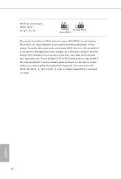
... BIOS manually. However, if the main BIOS is activated currently. English 20 BIOS Selection Jumper (BIOS_SEL1) (see p.6, No. 25) Default Backup BIOS (Main BIOS) his motherboard has two BIOS onboard, a main BIOS (BIOS_A) and a backup BIOS (BIOS_B), which BIOS is corrupted or damaged, please use "Secure Backup UEFI" in BIOS setup...
... BIOS manually. However, if the main BIOS is activated currently. English 20 BIOS Selection Jumper (BIOS_SEL1) (see p.6, No. 25) Default Backup BIOS (Main BIOS) his motherboard has two BIOS onboard, a main BIOS (BIOS_A) and a backup BIOS (BIOS_B), which BIOS is corrupted or damaged, please use "Secure Backup UEFI" in BIOS setup...

User Manual
Page 27
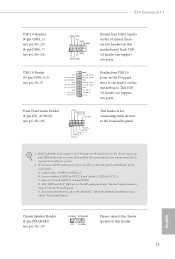
... the system is reading or writing data. he front panel design may conigure the way to turn of your chassis front panel module to the motherboard. he LED is of when the system is in S4 sleep state or powered of power switch, reset switch, power LED, hard drive activity LED..., reset switch and system status indicator on when the hard drive is operating. English 21 PLED (System Power LED): Connect to the pin assignments below. X99 Extreme4/3.1 2.6 Onboard Headers and Connectors Onboard headers and connectors are matched correctly.
... the system is reading or writing data. he front panel design may conigure the way to turn of your chassis front panel module to the motherboard. he LED is of when the system is in S4 sleep state or powered of power switch, reset switch, power LED, hard drive activity LED..., reset switch and system status indicator on when the hard drive is operating. English 21 PLED (System Power LED): Connect to the pin assignments below. X99 Extreme4/3.1 2.6 Onboard Headers and Connectors Onboard headers and connectors are matched correctly.
User Manual
Page 29
... them for the HD audio panel only. To activate the front mic, go to the "FrontMic" Tab in our manual and chassis manual to this motherboard. X99 Extreme4/3.1 USB 2.0 Headers (9-pin USB4_5) (see p.6, No. 23) (9-pin USB6_7) (see p.6, No. 24) USB_PWR PP+ GND DUMMY 1 GND P+ PUSB_PWR Besides four USB 2.0 ports on the I /O panel...
... them for the HD audio panel only. To activate the front mic, go to the "FrontMic" Tab in our manual and chassis manual to this motherboard. X99 Extreme4/3.1 USB 2.0 Headers (9-pin USB4_5) (see p.6, No. 23) (9-pin USB6_7) (see p.6, No. 24) USB_PWR PP+ GND DUMMY 1 GND P+ PUSB_PWR Besides four USB 2.0 ports on the I /O panel...
User Manual
Page 30
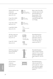
...CPU Fan Connectors (4-pin CPU_FAN1) (see p.6, No. 4) (3-pin CPU_FAN2) (see p.6, No. 3) 1 13 8 5 4 1 his motherboard provides a 24-pin ATX power connector. his motherboard provides a 4-Pin CPU fan (Quiet Fan) connector. ATX Power Connector (24-pin ATXPWR1) (see p.6, No. 8) 12 24 ATX 12V ...Power Connector (8-pin ATX12V1) (see p.6, No. 6) 4 3 21 GND +12V CPU_FAN_SPEED FAN_SPEED_CONTROL GND FAN_VOLTAGE CPU_FAN_SPEED his motherboard provides an 8-pin ATX 12V power connector. To use a 20-pin ATX power supply, please plug it to the ground pin. CHA_ FAN...
...CPU Fan Connectors (4-pin CPU_FAN1) (see p.6, No. 4) (3-pin CPU_FAN2) (see p.6, No. 3) 1 13 8 5 4 1 his motherboard provides a 24-pin ATX power connector. his motherboard provides a 4-Pin CPU fan (Quiet Fan) connector. ATX Power Connector (24-pin ATXPWR1) (see p.6, No. 8) 12 24 ATX 12V ...Power Connector (8-pin ATX12V1) (see p.6, No. 6) 4 3 21 GND +12V CPU_FAN_SPEED FAN_SPEED_CONTROL GND FAN_VOLTAGE CPU_FAN_SPEED his motherboard provides an 8-pin ATX 12V power connector. To use a 20-pin ATX power supply, please plug it to the ground pin. CHA_ FAN...

User Manual
Page 32
2.7 Smart Switches he motherboard has a Clear CMOS Switch, allowing users to quickly clear the CMOS values. English 26 his function is workable only when you power of your computer and unplug the power supply. Clear CMOS Switch (CLRCBTN) (see p.8, No. 14) Clear CMOS Switch allows users to clear the CMOS values.
2.7 Smart Switches he motherboard has a Clear CMOS Switch, allowing users to quickly clear the CMOS values. English 26 his function is workable only when you power of your computer and unplug the power supply. Clear CMOS Switch (CLRCBTN) (see p.8, No. 14) Clear CMOS Switch allows users to clear the CMOS values.

User Manual
Page 33
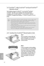
... card into PCIE1 slot and the other graphics card to the PCI Express graphics cards. 27 English It is not supported. X99 Extreme4/3.1 2.8 SLITM , 3-Way SLITMand Quad SLITM Operation Guide his motherboard supports NVIDIA® SLITM , 3-Way SLITM and Quad SLITM (Scalable Link Interface) technology that allows you install CPU with 28 lanes...
... card into PCIE1 slot and the other graphics card to the PCI Express graphics cards. 27 English It is not supported. X99 Extreme4/3.1 2.8 SLITM , 3-Way SLITMand Quad SLITM Operation Guide his motherboard supports NVIDIA® SLITM , 3-Way SLITM and Quad SLITM (Scalable Link Interface) technology that allows you install CPU with 28 lanes...
User Manual
Page 38
... the slots. Please refer to three identical PCI Express x16 graphics cards. 2.9 CrossFireXTM, 3-Way CrossFireXTM and Quad CrossFireXTM Operation Guide his motherboard supports CrossFireXTM, 3-way CrossFireXTM and Quad CrossFireXTM that allows you to install up to your graphics card vendor for details.) English 32 Diferent...from the AMD's website: www.amd.com 3. It is provided with the graphics card you pair a 12-pipe CrossFireXTM Edition card with this motherboard. You should only use a AMD certiied PSU. If you purchase, not bundled with a 16-pipe card, both cards will operate as ...
... the slots. Please refer to three identical PCI Express x16 graphics cards. 2.9 CrossFireXTM, 3-Way CrossFireXTM and Quad CrossFireXTM Operation Guide his motherboard supports CrossFireXTM, 3-way CrossFireXTM and Quad CrossFireXTM that allows you to install up to your graphics card vendor for details.) English 32 Diferent...from the AMD's website: www.amd.com 3. It is provided with the graphics card you pair a 12-pipe CrossFireXTM Edition card with this motherboard. You should only use a AMD certiied PSU. If you purchase, not bundled with a 16-pipe card, both cards will operate as ...

User Manual
Page 40
... card that the cards are properly seated on the slots. Make sure that is provided with the graphics card you purchase, not bundled with this motherboard.
... card that the cards are properly seated on the slots. Make sure that is provided with the graphics card you purchase, not bundled with this motherboard.

User Manual
Page 43
...by hand. Hand tighten the standof into place. Step 6 Tighten the screw with a screwdriver to secure the module into the desired nut location on the motherboard. Otherwise, release the standof by default. Please be used. Step 5 Align and gently insert the M.2 (NGFF) SSD module into the M.2 slot. ...module only its in one orientation. Step 4 Peel of the yellow protective ilm on the module type and length. E D C B A E D C B A C B A E D C B A E D NUT2 NUT1 X99 Extreme4/3.1 Step 3 Move the standof based on the nut to use the default nut. English 37
...by hand. Hand tighten the standof into place. Step 6 Tighten the screw with a screwdriver to secure the module into the desired nut location on the motherboard. Otherwise, release the standof by default. Please be used. Step 5 Align and gently insert the M.2 (NGFF) SSD module into the M.2 slot. ...module only its in one orientation. Step 4 Peel of the yellow protective ilm on the module type and length. E D C B A E D C B A C B A E D C B A E D NUT2 NUT1 X99 Extreme4/3.1 Step 3 Move the standof based on the nut to use the default nut. English 37
User Manual
Page 45
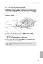
...to two SATA HDDs. 2. hen connect the SATA power connector(s) to your SATA HDD(s). hen connect the other end to a SATA port on the motherboard. Connection Diagram 1 HDD Saver Cable 2 SATA data cable *he HDD Saver Connector supports up to install the HDD Saver Cable. his design secures ... the HDDs' lifespans. Connect one end of the SATA data cable to your SATA HDD(s). * he diagram shown here is for reference only. 1. X99 Extreme4/3.1 2.11 HDD Saver Cable Installation Guide The HDD Saver Connector on this user manual. 39 English Connect one end of the HDD Saver Cable to...
...to two SATA HDDs. 2. hen connect the SATA power connector(s) to your SATA HDD(s). hen connect the other end to a SATA port on the motherboard. Connection Diagram 1 HDD Saver Cable 2 SATA data cable *he HDD Saver Connector supports up to install the HDD Saver Cable. his design secures ... the HDDs' lifespans. Connect one end of the SATA data cable to your SATA HDD(s). * he diagram shown here is for reference only. 1. X99 Extreme4/3.1 2.11 HDD Saver Cable Installation Guide The HDD Saver Connector on this user manual. 39 English Connect one end of the HDD Saver Cable to...

User Manual
Page 46
For charging Type-C USB devices, the device should support Type-C standards to 5V/3A. 2.12 ASRock USB 3.1/A+C Installation Guide Speciications Platform • Size: 3.1-in x 3.2-in, 7.9 cm x 8.1 cm Controller • ASMedia ASM1142 Controller PCIE • PCI...Connector • 1 x USB 3.1 Type-A Port (Supports ESD Protection (ASRock Full Spike Protection)) * For charging Type-A USB devices, we suggest using the Type-A connectors on your motherboard. • 1 x USB 3.1 Type-C Port (Supports ESD Protection (ASRock Full Spike Protection)) * his port supports power outputs up to adjust ...
For charging Type-C USB devices, the device should support Type-C standards to 5V/3A. 2.12 ASRock USB 3.1/A+C Installation Guide Speciications Platform • Size: 3.1-in x 3.2-in, 7.9 cm x 8.1 cm Controller • ASMedia ASM1142 Controller PCIE • PCI...Connector • 1 x USB 3.1 Type-A Port (Supports ESD Protection (ASRock Full Spike Protection)) * For charging Type-A USB devices, we suggest using the Type-A connectors on your motherboard. • 1 x USB 3.1 Type-C Port (Supports ESD Protection (ASRock Full Spike Protection)) * his port supports power outputs up to adjust ...

