
User Manual
Page 9
... Hardware Monitor, Fan Control, Overclocking, OC DNA and IES. It depends on page 13 for optimal system performance. In Fan Control, it with your friends. This convenient BIOS update tool allows you are allowed to overclock CPU frequency for proper connection. 6. Overclocking may be done at your system. You can use . 4. Currently Intel® Socket 2011 Sandy Bridge-E Processor doesn't support PCIE 3.0, but this motherboard supports 2-channel, 4-channel, 6-channel, and 8-channel modes. For audio output, this motherboard...
... Hardware Monitor, Fan Control, Overclocking, OC DNA and IES. It depends on page 13 for optimal system performance. In Fan Control, it with your friends. This convenient BIOS update tool allows you are allowed to overclock CPU frequency for proper connection. 6. Overclocking may be done at your system. You can use . 4. Currently Intel® Socket 2011 Sandy Bridge-E Processor doesn't support PCIE 3.0, but this motherboard supports 2-channel, 4-channel, 6-channel, and 8-channel modes. For audio output, this motherboard...
User Manual
Page 10
... the ASRock SmartView utility that cannot be noted that is Windows® 7 / 7 64 bit / VistaTM / VistaTM 64 bit, and your real-time newsfeed into the BIOS setup menu to access ASRock Instant Flash. ASRock XFast RAM is a new function that the USB flash drive or hard drive must use ASRock SmartView feature, please make sure your OS version is included into Standby mode (S1), Suspend to RAM (S3), hibernation mode (S4) or power...
... the ASRock SmartView utility that cannot be noted that is Windows® 7 / 7 64 bit / VistaTM / VistaTM 64 bit, and your real-time newsfeed into the BIOS setup menu to access ASRock Instant Flash. ASRock XFast RAM is a new function that the USB flash drive or hard drive must use ASRock SmartView feature, please make sure your OS version is included into Standby mode (S1), Suspend to RAM (S3), hibernation mode (S4) or power...
User Manual
Page 12
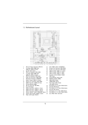
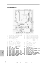
... Module Header 6 CPU Fan Connector (CPU_FAN1) (CIR1, Gray) 7 Power Fan Connector (PWR_FAN1) 28 Infrared Module Header (IR1) 8 ATX Power Connector (ATXPWR1) 29 COM Port Header (COM1) 9 USB 3.0 Header (USB3_2_3, Black) 30 HDMI_SPDIF Header 10 Chassis Fan Connector (CHA_FAN2) (HDMI_SPDIF1, Black) 11 SATA3 Connector (SATA3_A0, Gray) 31 Front Panel Audio Header 12 SPI Flash Memory (64Mb) (HD_AUDIO1, Black) 13 SB Fan Connector (SB_FAN1) 32 PCI Express 3.0 x16 Slot (PCIE4, Black) 14 Intel X79 Chipset 33 PCI Slot (PCI2, Black) 15 SATA3 Connectors (SATA3_0_1, Gray) 34 PCI Express...
... Module Header 6 CPU Fan Connector (CPU_FAN1) (CIR1, Gray) 7 Power Fan Connector (PWR_FAN1) 28 Infrared Module Header (IR1) 8 ATX Power Connector (ATXPWR1) 29 COM Port Header (COM1) 9 USB 3.0 Header (USB3_2_3, Black) 30 HDMI_SPDIF Header 10 Chassis Fan Connector (CHA_FAN2) (HDMI_SPDIF1, Black) 11 SATA3 Connector (SATA3_A0, Gray) 31 Front Panel Audio Header 12 SPI Flash Memory (64Mb) (HD_AUDIO1, Black) 13 SB Fan Connector (SB_FAN1) 32 PCI Express 3.0 x16 Slot (PCIE4, Black) 14 Intel X79 Chipset 33 PCI Slot (PCI2, Black) 15 SATA3 Connectors (SATA3_0_1, Gray) 34 PCI Express...

User Manual
Page 20
... connect a chassis fan to motherboard chassis fan connector (CHA_FAN1, CHA_FAN2 or CHA_FAN3) when using multiple graphics cards for information on future CPU updates and releases. Installing an expansion card Step 1. Remove the bracket facing the slot that you start the installation. Step 6. PCIE4 (PCIE 3.0 x16 slot) is recommended to install a PCI Express x16 graphics card on the slot. It depends on PCIE1 and PCIE3 slots. Step 2. 2.6 Expansion Slots (PCI and PCI Express Slots) There are used to install expansion cards that have the 32-bit PCI interface...
... connect a chassis fan to motherboard chassis fan connector (CHA_FAN1, CHA_FAN2 or CHA_FAN3) when using multiple graphics cards for information on future CPU updates and releases. Installing an expansion card Step 1. Remove the bracket facing the slot that you start the installation. Step 6. PCIE4 (PCIE 3.0 x16 slot) is recommended to install a PCI Express x16 graphics card on the slot. It depends on PCIE1 and PCIE3 slots. Step 2. 2.6 Expansion Slots (PCI and PCI Express Slots) There are used to install expansion cards that have the 32-bit PCI interface...

User Manual
Page 30
... have Windows® XP Service Pack 2 or higher installed in your Windows® taskbar. For Windows® 7 / VistaTM OS: Install the CATALYST Control Center. Double-click "ATI Catalyst Control Center". Install the required drivers to be installed (If you install two Radeon graphics cards). Please check Microsoft website for details. Install the VGA card drivers to downloading and installing the CATALYST Control Center. 2.8.2 Driver Installation and Setup Step 1. Restart your system, there is an optional download. Power...
... have Windows® XP Service Pack 2 or higher installed in your Windows® taskbar. For Windows® 7 / VistaTM OS: Install the CATALYST Control Center. Double-click "ATI Catalyst Control Center". Install the required drivers to be installed (If you install two Radeon graphics cards). Please check Microsoft website for details. Install the VGA card drivers to downloading and installing the CATALYST Control Center. 2.8.2 Driver Installation and Setup Step 1. Restart your system, there is an optional download. Power...

User Manual
Page 45
... the support CD to set RAID configuration. Enter UEFI SETUP UTILITY Advanced screen Storage Configuration. STEP 2: Use "RAID Installation Guide" to your optical drive first. If you want to install Windows® 7 / 7 64-bit / VistaTM / VistaTM 64-bit OS on Intel® SATA2 / SATA3 ports with RAID functions, please follow the steps below. A. Set the option "ASMedia SATA3 Bootable" to install Windows?" Then, the drivers compatible to load Intel® RAID drivers. B. Set the option "SATA Mode" to...
... the support CD to set RAID configuration. Enter UEFI SETUP UTILITY Advanced screen Storage Configuration. STEP 2: Use "RAID Installation Guide" to your optical drive first. If you want to install Windows® 7 / 7 64-bit / VistaTM / VistaTM 64-bit OS on Intel® SATA2 / SATA3 ports with RAID functions, please follow the steps below. A. Set the option "ASMedia SATA3 Bootable" to install Windows?" Then, the drivers compatible to load Intel® RAID drivers. B. Set the option "SATA Mode" to...

User Manual
Page 62
... or disable the use of USB 2.0 controller. There are connected. [Disabled] - Enables support for the details of these four options: [Enabled] - Enables legacy support if USB devices are four configuration options: [Enabled], [Auto], [Disabled] and [UEFI Setup Only]. USB devices are not allowed to use under UEFI setup and Windows / Linux OS. The default value is recommended to select [Disabled] to enter OS. [UEFI Setup Only] - USB devices are allowed to use only under legacy OS and UEFI setup when [Disabled] is [Enabled]. 62 3.4.7 USB Configuration USB 2.0 Controller Use...
... or disable the use of USB 2.0 controller. There are connected. [Disabled] - Enables support for the details of these four options: [Enabled] - Enables legacy support if USB devices are four configuration options: [Enabled], [Auto], [Disabled] and [UEFI Setup Only]. USB devices are not allowed to use under UEFI setup and Windows / Linux OS. The default value is recommended to select [Disabled] to enter OS. [UEFI Setup Only] - USB devices are allowed to use only under legacy OS and UEFI setup when [Disabled] is [Enabled]. 62 3.4.7 USB Configuration USB 2.0 Controller Use...

User Manual
Page 68
... the motherboard supports. Chapter 4: Software Support 4.1 Install Operating System This motherboard supports various Microsoft® Windows® operating systems: 7 / 7 64-bit / VistaTM / VistaTM 64-bit / XP / XP 64-bit. Please install the necessary drivers to install it. 4.2.4 Contact Information If you may contact your computer. Because motherboard settings and hardware options vary, use the setup procedures in your dealer for general reference only. If the Main Menu does not appear automatically, locate...
... the motherboard supports. Chapter 4: Software Support 4.1 Install Operating System This motherboard supports various Microsoft® Windows® operating systems: 7 / 7 64-bit / VistaTM / VistaTM 64-bit / XP / XP 64-bit. Please install the necessary drivers to install it. 4.2.4 Contact Information If you may contact your computer. Because motherboard settings and hardware options vary, use the setup procedures in your dealer for general reference only. If the Main Menu does not appear automatically, locate...
Quick Installation Guide
Page 2
...6 CPU Fan Connector (CPU_FAN1) (CIR1, Gray) 7 Power Fan Connector (PWR_FAN1) 28 Infrared Module Header (IR1) 8 ATX Power Connector (ATXPWR1) 29 COM Port Header (COM1) 9 USB 3.0 Header (USB3_2_3, Black) 30 HDMI_SPDIF Header 10 Chassis Fan Connector (CHA_FAN2) (HDMI_SPDIF1, Black) 11 SATA3 Connector (SATA3_A0, Gray) 31 Front Panel Audio Header 12 SPI Flash Memory (64Mb) (HD_AUDIO1, Black) 13 SB Fan Connector (SB_FAN1) 32 PCI Express 3.0 x16 Slot (PCIE4, Black) 14 Intel X79 Chipset 33 PCI Slot (PCI2, Black) 15 SATA3 Connectors (SATA3_0_1, Gray) 34 PCI Express 3.0 x16 Slot...
...6 CPU Fan Connector (CPU_FAN1) (CIR1, Gray) 7 Power Fan Connector (PWR_FAN1) 28 Infrared Module Header (IR1) 8 ATX Power Connector (ATXPWR1) 29 COM Port Header (COM1) 9 USB 3.0 Header (USB3_2_3, Black) 30 HDMI_SPDIF Header 10 Chassis Fan Connector (CHA_FAN2) (HDMI_SPDIF1, Black) 11 SATA3 Connector (SATA3_A0, Gray) 31 Front Panel Audio Header 12 SPI Flash Memory (64Mb) (HD_AUDIO1, Black) 13 SB Fan Connector (SB_FAN1) 32 PCI Express 3.0 x16 Slot (PCIE4, Black) 14 Intel X79 Chipset 33 PCI Slot (PCI2, Black) 15 SATA3 Connectors (SATA3_0_1, Gray) 34 PCI Express 3.0 x16 Slot...
Quick Installation Guide
Page 3
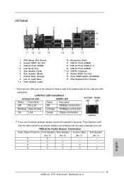
...) 8 Line In (Light Blue) ** 9 Front Speaker (Lime) 10 11 12 13 *** 14 15 16 17 Microphone (Pink) USB 2.0 Ports (USB45) USB 3.0 Ports (USB3_0_1) USB 2.0 Ports (USB23) eSATA3 Connector Optical SPDIF Out Port Clear CMOS Switch (CLRCBTN) PS/2 Keyboard Port (Purple) * There are two LED next to the table below for Audio Output Connection Audio Output Channels Front Speaker Rear Speaker Central / Bass Side Speaker (No. 9) (No. 6) (No. 7) (No. 5) 2 V -- -- -- 4 V V -- -- 6 V V V -- 8 V V V V 3 ASRock X79 Extreme3 Motherboard English Please refer to the LAN port.
...) 8 Line In (Light Blue) ** 9 Front Speaker (Lime) 10 11 12 13 *** 14 15 16 17 Microphone (Pink) USB 2.0 Ports (USB45) USB 3.0 Ports (USB3_0_1) USB 2.0 Ports (USB23) eSATA3 Connector Optical SPDIF Out Port Clear CMOS Switch (CLRCBTN) PS/2 Keyboard Port (Purple) * There are two LED next to the table below for Audio Output Connection Audio Output Channels Front Speaker Rear Speaker Central / Bass Side Speaker (No. 9) (No. 6) (No. 7) (No. 5) 2 V -- -- -- 4 V V -- -- 6 V V V -- 8 V V V V 3 ASRock X79 Extreme3 Motherboard English Please refer to the LAN port.
Quick Installation Guide
Page 5
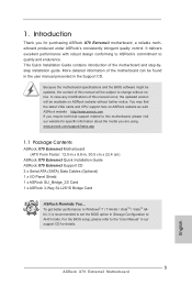
... find the latest VGA cards and CPU support lists on ASRock website without notice. To get better performance in Windows® 7 / 7 64-bit / VistaTM / VistaTM 64bit, it is recommended to set the BIOS option in Storage Configuration to the "User Manual" in , 30.5 cm x 22.4 cm) ASRock X79 Extreme3 Quick Installation Guide ASRock X79 Extreme3 Support CD 3 x Serial ATA (SATA) Data Cables (Optional) 1 x I/O Panel Shield 1 x ASRock SLI_Bridge_2S Card 1 x ASRock 3-Way SLI-2S1S Bridge Card ASRock Reminds You... This Quick Installation Guide contains introduction of this motherboard, please visit...
... find the latest VGA cards and CPU support lists on ASRock website without notice. To get better performance in Windows® 7 / 7 64-bit / VistaTM / VistaTM 64bit, it is recommended to set the BIOS option in Storage Configuration to the "User Manual" in , 30.5 cm x 22.4 cm) ASRock X79 Extreme3 Quick Installation Guide ASRock X79 Extreme3 Support CD 3 x Serial ATA (SATA) Data Cables (Optional) 1 x I/O Panel Shield 1 x ASRock SLI_Bridge_2S Card 1 x ASRock 3-Way SLI-2S1S Bridge Card ASRock Reminds You... This Quick Installation Guide contains introduction of this motherboard, please visit...

Quick Installation Guide
Page 9
... enable PCIE 3.0. About the setting of "Hyper Threading Technology", please check page 55 of output phases to overclock CPU frequency for you can reduce the number of the User Manual in Flash ROM. It depends on page 16 for system usage under Windows® 7 / VistaTM / XP. ASRock Extreme Tuning Utility (AXTU) is an all-in-one tool to the operating system limitation, the actual memory size...
... enable PCIE 3.0. About the setting of "Hyper Threading Technology", please check page 55 of output phases to overclock CPU frequency for you can reduce the number of the User Manual in Flash ROM. It depends on page 16 for system usage under Windows® 7 / VistaTM / XP. ASRock Extreme Tuning Utility (AXTU) is an all-in-one tool to the operating system limitation, the actual memory size...
Quick Installation Guide
Page 10
... device. 11. It fully utilizes the memory space that helps you to quickly charge many Apple devices simultaneously and even supports continuous charging when your PC enters into Standby mode (S1), Suspend to RAM (S3), hibernation mode (S4) or power off (S5). ASRock XFast RAM shortens the loading time of Charging the BC 1.1 standard smart devices. this tool and save the new BIOS file to your USB flash drive, floppy disk or hard drive...
... device. 11. It fully utilizes the memory space that helps you to quickly charge many Apple devices simultaneously and even supports continuous charging when your PC enters into Standby mode (S1), Suspend to RAM (S3), hibernation mode (S4) or power off (S5). ASRock XFast RAM shortens the loading time of Charging the BC 1.1 standard smart devices. this tool and save the new BIOS file to your USB flash drive, floppy disk or hard drive...

Quick Installation Guide
Page 17
... power cord is already installed in a chassis). Step 2. Step 4. Step 5. Replace the system cover. 17 ASRock X79 Extreme3 Motherboard English Currently Intel® Socket 2011 Sandy Bridge-E Processor doesn't support PCIE 3.0, but this motherboard. PCIE slots:PCIE1 / PCIE3 (PCIE 3.0 x16 slots) are used to install a PCI Express graphics card to support 3-Way CrossFireXTM, 3-Way SLITM function or to enable PCIE 3.0. Therefore, both these two slots will work at x8 bandwidth. 4. Remove the bracket facing the slot that have the 32-bit PCI...
... power cord is already installed in a chassis). Step 2. Step 4. Step 5. Replace the system cover. 17 ASRock X79 Extreme3 Motherboard English Currently Intel® Socket 2011 Sandy Bridge-E Processor doesn't support PCIE 3.0, but this motherboard. PCIE slots:PCIE1 / PCIE3 (PCIE 3.0 x16 slots) are used to install a PCI Express graphics card to support 3-Way CrossFireXTM, 3-Way SLITM function or to enable PCIE 3.0. Therefore, both these two slots will work at x8 bandwidth. 4. Remove the bracket facing the slot that have the 32-bit PCI...

Quick Installation Guide
Page 27
... Windows® 7 / VistaTM OS: Install the CATALYST Control Center. Select "3 GPUs" and click "OK" (if you install two Radeon graphics cards). English 27 ASRock X79 Extreme3 Motherboard The Catalyst Uninstaller is no need to installation. You must have any previously installed Catalyst drivers prior to download it again): http://www.microsoft.com/windowsxp/sp2/default.mspx B. Please check AMD website for ATITM driver updates. Double-click "ATI Catalyst Control...
... Windows® 7 / VistaTM OS: Install the CATALYST Control Center. Select "3 GPUs" and click "OK" (if you install two Radeon graphics cards). English 27 ASRock X79 Extreme3 Motherboard The Catalyst Uninstaller is no need to installation. You must have any previously installed Catalyst drivers prior to download it again): http://www.microsoft.com/windowsxp/sp2/default.mspx B. Please check AMD website for ATITM driver updates. Double-click "ATI Catalyst Control...

Quick Installation Guide
Page 38
... 64-bit OS on the support CD driver page. Please follow below steps. A. B. Therefore, the drivers you install can be auto-detected and listed on your optical drive first. Then, the drivers compatible to your SATA / SATA2 / SATA3 HDDs without NCQ function STEP 1: Set Up UEFI. 2.13 Driver Installation Guide To install the drivers to your system, please insert the support CD to your system. 38 ASRock X79 Extreme3 Motherboard English Enter UEFI SETUP UTILITY Advanced screen Storage Configuration. Set the option "SATA Mode" to [IDE...
... 64-bit OS on the support CD driver page. Please follow below steps. A. B. Therefore, the drivers you install can be auto-detected and listed on your optical drive first. Then, the drivers compatible to your SATA / SATA2 / SATA3 HDDs without NCQ function STEP 1: Set Up UEFI. 2.13 Driver Installation Guide To install the drivers to your system, please insert the support CD to your system. 38 ASRock X79 Extreme3 Motherboard English Enter UEFI SETUP UTILITY Advanced screen Storage Configuration. Set the option "SATA Mode" to [IDE...
Quick Installation Guide
Page 40
... useful utilities that will display the Main Menu automatically if "AUTORUN" is enabled in the Support CD. 4. For the detailed information about BIOS Setup, please refer to display the menus. 40 ASRock X79 Extreme3 Motherboard English If the Main Menu does not appear automatically, locate and double-click on the file "ASSETUP.EXE" from the BIN folder in the Support CD to the User Manual (PDF file) contained in your CD-ROM drive. BIOS Information The Flash Memory...
... useful utilities that will display the Main Menu automatically if "AUTORUN" is enabled in the Support CD. 4. For the detailed information about BIOS Setup, please refer to display the menus. 40 ASRock X79 Extreme3 Motherboard English If the Main Menu does not appear automatically, locate and double-click on the file "ASSETUP.EXE" from the BIN folder in the Support CD to the User Manual (PDF file) contained in your CD-ROM drive. BIOS Information The Flash Memory...

Quick Installation Guide
Page 202
.... Disable System Restore. Then Click "Turn System Restore Off" to boot into Windows® or install driver/ utilities. F. b. Then Press "Ok". 202 ASRock X79 Extreme3 Motherboard English Windows® VistaTM 64-bit: Microsoft® does not provide hotfix for System Restore. Follow Windows® Installation Guide to install OS by following instructions to fix this problem. E. Then press "Enter". a. Continue to install OS. The steps listed below are Microsoft®'s suggested solution: A. Type...
.... Disable System Restore. Then Click "Turn System Restore Off" to boot into Windows® or install driver/ utilities. F. b. Then Press "Ok". 202 ASRock X79 Extreme3 Motherboard English Windows® VistaTM 64-bit: Microsoft® does not provide hotfix for System Restore. Follow Windows® Installation Guide to install OS by following instructions to fix this problem. E. Then press "Enter". a. Continue to install OS. The steps listed below are Microsoft®'s suggested solution: A. Type...

RAID Installation Guide
Page 6
... Support CD, "Guide to SATA Hard Disks Installation and RAID Configuration", which is located in the folder at the following path: .. \ RAID Installation Guide STEP 3: Install Windows® 7 / 7 64-bit / VistaTM / VistaTM 64-bit OS on your SATA / SATA2 / SATA3 HDDs with RAID functions, please follow the procedures below. B. STEP 2: Use "RAID Installation Guide" to [RAID]. If you need to use both "RAID Installation Guide" and "Intel Rapid Storage Information" for proper configuration. Enter BIOS SETUP UTILITY Advanced screen Storage...
... Support CD, "Guide to SATA Hard Disks Installation and RAID Configuration", which is located in the folder at the following path: .. \ RAID Installation Guide STEP 3: Install Windows® 7 / 7 64-bit / VistaTM / VistaTM 64-bit OS on your SATA / SATA2 / SATA3 HDDs with RAID functions, please follow the procedures below. B. STEP 2: Use "RAID Installation Guide" to [RAID]. If you need to use both "RAID Installation Guide" and "Intel Rapid Storage Information" for proper configuration. Enter BIOS SETUP UTILITY Advanced screen Storage...

Intel Rapid Storage Guide
Page 13
... Floppy Configuration Utility to create a floppy disk with a screen asking you need to scroll through the list as all controllers may not be prompted Note with the Note necessary files. 4. When you have successfully installed the driver and Windows setup should continue. Use the up and down arrow keys to install a third party SCSI or RAID driver. This message appears at the beginning of available SCSI adapters. Press Enter...
... Floppy Configuration Utility to create a floppy disk with a screen asking you need to scroll through the list as all controllers may not be prompted Note with the Note necessary files. 4. When you have successfully installed the driver and Windows setup should continue. Use the up and down arrow keys to install a third party SCSI or RAID driver. This message appears at the beginning of available SCSI adapters. Press Enter...


