RAID Installation Guide
Page 2
... install SATA hard disks on SATA ports. 2 For SATA installation guide, please refer to SATA Hard Disks Installation 1.1 Serial ATA (SATA) Hard Disks Installation Intel X79 chipset supports Serial ATA (SATA) hard disks with RAID functions, including RAID 0, RAID 1, RAID 5, RAID 10 and Intel Rapid Storage. 1. Guide to Serial ATA (SATA...
... install SATA hard disks on SATA ports. 2 For SATA installation guide, please refer to SATA Hard Disks Installation 1.1 Serial ATA (SATA) Hard Disks Installation Intel X79 chipset supports Serial ATA (SATA) hard disks with RAID functions, including RAID 0, RAID 1, RAID 5, RAID 10 and Intel Rapid Storage. 1. Guide to Serial ATA (SATA...
User Manual
Page 1
All rights reserved. 1 X79 Extreme11 User Manual Version 1.0 Published April 2012 Copyright©2012 ASRock INC.
All rights reserved. 1 X79 Extreme11 User Manual Version 1.0 Published April 2012 Copyright©2012 ASRock INC.

User Manual
Page 2
...any errors or omissions that may apply, see www.dtsc.ca.gov/hazardouswaste/perchlorate" ASRock Website: http://www.asrock.com 2 With respect to the contents of this manual, ASRock does not provide warranty of any kind, either expressed or implied, including but not .... "Perchlorate Material-special handling may cause undesired operation. Disclaimer: Specifications and information contained in this manual are used only for backup purpose, without written consent of ASRock Inc. Operation is subject to the following two conditions: (1) this device may not cause harmful ...
...any errors or omissions that may apply, see www.dtsc.ca.gov/hazardouswaste/perchlorate" ASRock Website: http://www.asrock.com 2 With respect to the contents of this manual, ASRock does not provide warranty of any kind, either expressed or implied, including but not .... "Perchlorate Material-special handling may cause undesired operation. Disclaimer: Specifications and information contained in this manual are used only for backup purpose, without written consent of ASRock Inc. Operation is subject to the following two conditions: (1) this device may not cause harmful ...

User Manual
Page 5
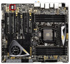
... BIOS setup, please refer to this manual, chapter 1 and 2 contains introduction of the Support CD. www.asrock.com/support/index.asp 1.1 Package Contents ASRock X79 Extreme11 Motherboard (CEB Form Factor: 12.0-in x 10.5-in Storage Configuration to set the BIOS option in , 30.5 cm x 26.7 cm) ASRock X79 Extreme11 Quick Installation Guide ASRock X79 Extreme11 Support CD 6 x Serial ATA (SATA) Data...
... BIOS setup, please refer to this manual, chapter 1 and 2 contains introduction of the Support CD. www.asrock.com/support/index.asp 1.1 Package Contents ASRock X79 Extreme11 Motherboard (CEB Form Factor: 12.0-in x 10.5-in Storage Configuration to set the BIOS option in , 30.5 cm x 26.7 cm) ASRock X79 Extreme11 Quick Installation Guide ASRock X79 Extreme11 Support CD 6 x Serial ATA (SATA) Data...
User Manual
Page 18
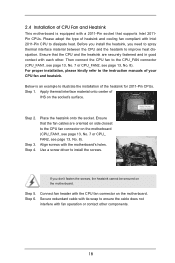
... on the motherboard. Use a screw driver to dissipate heat. Step 5. Step 6. 2.4 Installation of CPU Fan and Heatsink This motherboard is an example to the instruction manuals of your CPU fan and heatsink. Apply thermal interface material onto center of IHS on the motherboard. Connect fan header with the motherboard's holes. Step...
... on the motherboard. Use a screw driver to dissipate heat. Step 5. Step 6. 2.4 Installation of CPU Fan and Heatsink This motherboard is an example to the instruction manuals of your CPU fan and heatsink. Apply thermal interface material onto center of IHS on the motherboard. Connect fan header with the motherboard's holes. Step...

User Manual
Page 39
... released or will release in any 3D application. Please check AMD's website for detailed installation guide. For other Radeon graphics card to AMD graphics card manuals for CrossFireXTM driver updates. 1. Insert one Radeon graphics card into PCIE1 slot and the other CrossFireXTM cards that the cards are supported with a 16-pipe...
... released or will release in any 3D application. Please check AMD's website for detailed installation guide. For other Radeon graphics card to AMD graphics card manuals for CrossFireXTM driver updates. 1. Insert one Radeon graphics card into PCIE1 slot and the other CrossFireXTM cards that the cards are supported with a 16-pipe...

User Manual
Page 50
... wireless transmitting and receiving infrared module. B. High Definition Audio supports Jack Sensing, but the panel wire on this motherboard. Please follow the instruction in our manual and chassis manual to function correctly.
... wireless transmitting and receiving infrared module. B. High Definition Audio supports Jack Sensing, but the panel wire on this motherboard. Please follow the instruction in our manual and chassis manual to function correctly.
User Manual
Page 63
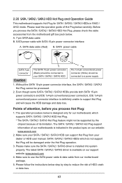
...data cable from your SATA / SATA2 / SATA3 HDD The 1x4-pin conventional power connector (White) should be connected to your dealer or HDD user manual. Please read the operation guide of our motherboards is installed into system properly. SATA data cable (Red) B. Even though some SATA / SATA2 /... SATA 15-pin power connectors and IDE 1x4-pin conventional power connectors, IDE 1x4-pin conventional power connector interface is available on our website: www.asrock.com 2. SATA / SATA2 / SATA3 HDDs which supports SATA / SATA2 / SATA3 HDD Hot Plug. * The SATA / SATA2 / SATA3 Hot Plug ...
...data cable from your SATA / SATA2 / SATA3 HDD The 1x4-pin conventional power connector (White) should be connected to your dealer or HDD user manual. Please read the operation guide of our motherboards is installed into system properly. SATA data cable (Red) B. Even though some SATA / SATA2 /... SATA 15-pin power connectors and IDE 1x4-pin conventional power connectors, IDE 1x4-pin conventional power connector interface is available on our website: www.asrock.com 2. SATA / SATA2 / SATA3 HDDs which supports SATA / SATA2 / SATA3 HDD Hot Plug. * The SATA / SATA2 / SATA3 Hot Plug ...

User Manual
Page 67
... set the selection from [Auto] to the warning on page 9 for the possible overclocking risk before you apply Untied Overclocking Technology. 67 Please refer to [Manual]. 2.24 Untied Overclocking Technology This motherboard supports Untied Overclocking Technology, which means during overclocking, but PCI / PCIE buses are in the fixed mode so that...
... set the selection from [Auto] to the warning on page 9 for the possible overclocking risk before you apply Untied Overclocking Technology. 67 Please refer to [Manual]. 2.24 Untied Overclocking Technology This motherboard supports Untied Overclocking Technology, which means during overclocking, but PCI / PCIE buses are in the fixed mode so that...
User Manual
Page 74
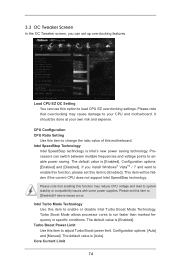
... Setting Use this item to change the ratio value of this item to enable or disable Intel Turbo Boost Mode Technology. Configuration options: [Auto] and [Manual]. Core Current Limit 74 It should be hidden if the current CPU does not support Intel SpeedStep technology. Please set this function may cause damage...
... Setting Use this item to change the ratio value of this item to enable or disable Intel Turbo Boost Mode Technology. Configuration options: [Auto] and [Manual]. Core Current Limit 74 It should be hidden if the current CPU does not support Intel SpeedStep technology. Please set this function may cause damage...

User Manual
Page 75
... options: [Auto], [Default], [Profile 1] and [Profile 2]. The default is [All]. DRAM tRP Use this item to change RAS# to CAS# Delay (tRCD) Auto/Manual setting. The default is [100.0]. Host Clock Override (BCLK) Use this to enable in each processor package. DRAM tRCD Use this item to change Row... Precharge Time (tRP) Auto/Manual setting. Use this item to add voltage when CPU is in Turbo mode. Active Processor Cores Use this item to select the number of cores...
... options: [Auto], [Default], [Profile 1] and [Profile 2]. The default is [All]. DRAM tRP Use this item to change RAS# to CAS# Delay (tRCD) Auto/Manual setting. The default is [100.0]. Host Clock Override (BCLK) Use this to enable in each processor package. DRAM tRCD Use this item to change Row... Precharge Time (tRP) Auto/Manual setting. Use this item to add voltage when CPU is in Turbo mode. Active Processor Cores Use this item to select the number of cores...

User Manual
Page 76
... (CH A) setting. The default is [Auto]. Configuration options: [Auto], [Slow] and [Fast]. ODT WR (CH A) Use this item to change Read to Precharge (tRTP) Auto/Manual setting. ODT WR (CH B) Use this item to change ODT NOM (CH A) setting. The default is [Auto]. The default is [Auto]. The default is [Auto... [Auto]. ODT NOM (CH A) Use this item to change ODT WR (CH B) setting. DRAM Power Down Mode Use this item to change Command Rate Auto/Manual setting. ODT WR (CH C) 76 The default is [Auto]. DRAM tWTR Use this item to change CAS# Write Latency (tCWL) Auto...
... (CH A) setting. The default is [Auto]. Configuration options: [Auto], [Slow] and [Fast]. ODT WR (CH A) Use this item to change Read to Precharge (tRTP) Auto/Manual setting. ODT WR (CH B) Use this item to change ODT NOM (CH A) setting. The default is [Auto]. The default is [Auto]. The default is [Auto... [Auto]. ODT NOM (CH A) Use this item to change ODT WR (CH B) setting. DRAM Power Down Mode Use this item to change Command Rate Auto/Manual setting. ODT WR (CH C) 76 The default is [Auto]. DRAM tWTR Use this item to change CAS# Write Latency (tCWL) Auto...

User Manual
Page 77
.... Channel Interleaving It allows you to change ODT WR (CH C) setting. The default is [Auto]. DRAM tWRDR Use this item to change DRAM tWRDD Auto/Manual setting. DRAM tRWDD Use this item to change ODT WR (CH D) setting. DRAM tWWDD Use this item to change DRAM tWRDR Auto.... DRAM tRWSR Use this item to configure Memory Mode. The default is [Auto]. Memory Mode Use this item to change DRAM tRWDR Auto/Manual setting. The default value is [Auto]. The default value is [Auto]. The default value is [Auto]. Rank Interleaving It allows you to configure Memory Power ...
.... Channel Interleaving It allows you to change ODT WR (CH C) setting. The default is [Auto]. DRAM tWRDR Use this item to change DRAM tWRDD Auto/Manual setting. DRAM tRWDD Use this item to change ODT WR (CH D) setting. DRAM tWWDD Use this item to change DRAM tWRDR Auto.... DRAM tRWSR Use this item to configure Memory Mode. The default is [Auto]. Memory Mode Use this item to change DRAM tRWDR Auto/Manual setting. The default value is [Auto]. The default value is [Auto]. The default value is [Auto]. Rank Interleaving It allows you to configure Memory Power ...

User Manual
Page 78
... Use this to select VCCSA Voltage. DRAM Fine Tuning - VCCSA Voltage Use this item to change DRAM tRRDD Auto/Manual setting. VTT Voltage Use this item to change DRAM tRRDR Auto/Manual setting. The default value is [Auto]. The default value is [Auto]. DRAM tWWDR Use this to select VTT...Use this item to configure DRAM Fine Tuning - The default value is [Auto]. Load Power Saving Mode Use this item to change DRAM tWWDR Auto/Manual setting. SP Use this option to configure DRAM Fine Tuning - The default value is [Auto]. PCH 1.1V Voltage Use this item to load ...
... Use this to select VCCSA Voltage. DRAM Fine Tuning - VCCSA Voltage Use this item to change DRAM tRRDD Auto/Manual setting. VTT Voltage Use this item to change DRAM tRRDR Auto/Manual setting. The default value is [Auto]. The default value is [Auto]. DRAM tWWDR Use this to select VTT...Use this item to configure DRAM Fine Tuning - The default value is [Auto]. Load Power Saving Mode Use this item to change DRAM tWWDR Auto/Manual setting. SP Use this option to configure DRAM Fine Tuning - The default value is [Auto]. PCH 1.1V Voltage Use this item to load ...
User Manual
Page 81
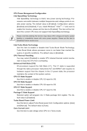
... [Enabled]. The default value is Intel's new power saving technology. Enhanced Halt State (C1E) All processors support the Halt State (C1). Configuration options: [Auto] and [Manual]. Processors can switch between multiple frequencies and voltage points to run faster than marked frequency in Turbo mode. 81 The default value is in specific...
... [Enabled]. The default value is Intel's new power saving technology. Enhanced Halt State (C1E) All processors support the Halt State (C1). Configuration options: [Auto] and [Manual]. Processors can switch between multiple frequencies and voltage points to run faster than marked frequency in Turbo mode. 81 The default value is in specific...

User Manual
Page 93
Chassis Fan 1 Setting This allows you to activate ASRock X-FAN. Configuration options: [Level 1] to enable or disable Over Temperature Protection. Chassis Fan 3 Setting This allows you to set chassis fan 3's speed. SB Fan 1 Setting ... set the target temperature to set chassis fan 1's speed. The default value is [Enabled]. 93 The default value is [Level 1] (ASRock X-FAN deactivated). Configuration options: [Full On], [Automatic Mode] and [Manual]. The default value is [50oC/122oF]. Configuration options: [Full On] and [Automatic mode]. Target Fan Speed This allows you to set...
Chassis Fan 1 Setting This allows you to activate ASRock X-FAN. Configuration options: [Level 1] to enable or disable Over Temperature Protection. Chassis Fan 3 Setting This allows you to set chassis fan 3's speed. SB Fan 1 Setting ... set the target temperature to set chassis fan 1's speed. The default value is [Enabled]. 93 The default value is [Level 1] (ASRock X-FAN deactivated). Configuration options: [Full On], [Automatic Mode] and [Manual]. The default value is [50oC/122oF]. Configuration options: [Full On] and [Automatic mode]. Target Fan Speed This allows you to set...
Quick Installation Guide
Page 4
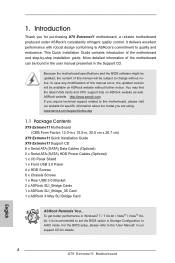
... of this motherboard, please visit our website for specific information about the model you for details. 4 X79 Extreme11 Motherboard English It delivers excellent performance with robust design conforming to ASRock's commitment to this manual will be available on ASRock website as well. More detailed information of the motherboard and step-by-step installation guide. Introduction...
... of this motherboard, please visit our website for specific information about the model you for details. 4 X79 Extreme11 Motherboard English It delivers excellent performance with robust design conforming to ASRock's commitment to this manual will be available on ASRock website as well. More detailed information of the motherboard and step-by-step installation guide. Introduction...
Quick Installation Guide
Page 8
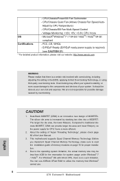
...For detailed product information, please visit our website: http://www.asrock.com WARNING Please realize that Windows® cannot use ASRock XFast RAM to the operating system limitation, the actual memory ...two dies into a MOSFET. Compared to traditional discrete MOSFET, DSM can use . 8 X79 Extreme11 Motherboard English Due to utilize the memory that there is no such limitation. Before you implement.... 4. FCC, CE, WHQL - The silicon die area is an innovative new design of the User Manual. 3. The larger the die area, the lower Rds(on). Voltage Monitoring: +12V, +5V, +3.3V...
...For detailed product information, please visit our website: http://www.asrock.com WARNING Please realize that Windows® cannot use ASRock XFast RAM to the operating system limitation, the actual memory ...two dies into a MOSFET. Compared to traditional discrete MOSFET, DSM can use . 8 X79 Extreme11 Motherboard English Due to utilize the memory that there is no such limitation. Before you implement.... 4. FCC, CE, WHQL - The silicon die area is an innovative new design of the User Manual. 3. The larger the die area, the lower Rds(on). Voltage Monitoring: +12V, +5V, +3.3V...

Quick Installation Guide
Page 15
...dissipate heat. Step 2. Align screws with the CPU fan connector on the motherboard. Step 6. Then connect the CPU fan to the instruction manuals of your CPU fan and heatsink. Step 5. Connect fan header with the motherboard's holes. Step 3. For proper installation, please kindly ...the socket's surface. Use a screw driver to illustrate the installation of the heatsink for 2011-Pin CPUs. Step 4. English 15 X79 Extreme11 Motherboard If you need to spray thermal interface material between the CPU and the heatsink to ensure the cable does not interfere with...
...dissipate heat. Step 2. Align screws with the CPU fan connector on the motherboard. Step 6. Then connect the CPU fan to the instruction manuals of your CPU fan and heatsink. Step 5. Connect fan header with the motherboard's holes. Step 3. For proper installation, please kindly ...the socket's surface. Use a screw driver to illustrate the installation of the heatsink for 2011-Pin CPUs. Step 4. English 15 X79 Extreme11 Motherboard If you need to spray thermal interface material between the CPU and the heatsink to ensure the cable does not interfere with...

Quick Installation Guide
Page 36
... three CrossFireXTM components, a CrossFireXTM Ready graphics card, a CrossFireXTM Ready motherboard and a CrossFireXTM Edition co-processor graphics card, must be installed correctly to AMD graphics card manuals for CrossFireXTM driver updates. 1. Please check AMD's website for detailed installation guide. English 36 X79 Extreme11 Motherboard Step 1.
... three CrossFireXTM components, a CrossFireXTM Ready graphics card, a CrossFireXTM Ready motherboard and a CrossFireXTM Edition co-processor graphics card, must be installed correctly to AMD graphics card manuals for CrossFireXTM driver updates. 1. Please check AMD's website for detailed installation guide. English 36 X79 Extreme11 Motherboard Step 1.
